Page is loading ...

2
Sicherheitshinweise
- Prüfen Sie vor jedem Start den festen Sitz des Motors und der Luftschrauben - insbesondere nach dem Transport, härteren
Landungen sowie Abstürzen. Prüfen Sie ebenfalls vor jedem Start den festen Sitz und die richtige Position der Tragflächen auf dem
Rumpf.
- Akku erst einstecken, wenn Ihr Sender eingeschaltet ist und Sie sicher sind, daß das Bedienelement für die Motorsteuerung auf
"AUS" steht.
- Im startbereiten Zustand nicht in den Bereich der Luftschraube greifen.
Vorsicht in der Luftschraubendrehebene - auch Zuschauer zur Seite bitten!
- Zwischen den Flügen die Motortemperatur durch vorsichtige Fingerprobe prüfen und
vor einem Neustart den Motor ausreichend abkühlen lassen. Die Temperatur ist richtig, wenn Sie den Motor problemlos berühren
können. Insbesondere bei hohen Außentemperaturen kann dieses bis zu 15 Minuten dauern.
- Denken Sie immer daran: Niemals auf Personen und Tiere zufliegen.
Conseils de sécurité
- Avant chaque décollage, vérifiez la fixation du moteur et de l'hélice, notamment après le transport, après les atterrissages violents
et après un “Crash”. Vérifiez également, avant chaque décollage la fixation ainsi que le positionnement de l’aile par rapport au
fuselage.
- Ne branchez l’accu de propulsion que si vous êtes sûr que votre émetteur est allumé et que l’élément de commande moteur est en
position “ARRET”.
- Ne mettez pas vos doigts dans l’hélice! Attention à la mise en marche, demandez également aux spectateurs de reculer.
- Entre deux vols, vérifiez en posant un doigt dessus, la température du moteur, laissezle refroidir suffisamment avant le prochain
décollage. La température est correcte si vous pouvez maintenir votre doigt ou votre main sur le moteur. Le temps de refroidissement
peut varier jusqu’à 15 minutes s’il fait particulièrement chaud.
- Pensez-y toujours: ne volez jamais vers ou au-dessus des personnes ou des animaux.
Safety notes
- Before every flight check that the motor and propeller are in place and secure - especially after transporting the model, and after
hard landings and crashes. Check also that the wing is correctly located and firmly secured on the fuselage before each flight.
- Don’t plug in the battery until you have switched on the transmitter, and you are sure that the motor control on the transmitter is set
to “OFF”.
- When the model is switched on, ready to fly, take care not to touch the propeller. Keep well clear of the propeller disc too, and ask
spectators to stay back.
- Allow the motor to cool down after each flight. You can check this by carefully touching the motor case with your finger. The
temperature is correct when you can hold your finger on the case without any problem. On hot days this may take up to 15 minutes.
- Please keep in mind at all times: don’t fly towards people or animals.
Note di sicurezza
- Prima di ogni decollo controllare che il motore e la eliche siano fissati stabilmente - specialmente dopo il trasporto, atterraggi duri
e se il modello è precipitato. Controllare prima del decollo anche il fissaggio e la posizione corretta delle ali sulla fusoliera.
- Collegare la batteria solo quando la radio è inserita ed il comando del motore è sicuramente in posizione ”SPENTO”.
- Prima del decollo non avvicinarsi al campo di rotazione della eliche. Attenzione alla eliche in movimento - pregare che eventuali
spettatori si portino alla dovuta distanza di sicurezza!
- Tra un volo e l’altro controllare cautamente con le dita la temperatura del motore e farli raffreddare sufficientemente prima di ogni
nuovo decollo. La temperatura è giusta se si possono toccare senza problemi. Specialmente con una temperatura esterna alta
questo può durare fino a 15 minuti.
- Fare attenzione: Non volare mai nella direzione di persone ed animali.
Advertencias de seguridad
- Compruebe antes de cada despegue que el motor y la hélice estén fuertemente sujetados, sobretodo después de haberlo transportado,
de aterrizajes más fuertes así como después de una caída. Compruebe igualmente antes de cada despegue que las alas estén bien
sujetas y bien colocadas en el fuselaje.
- Conectar la batería, cuando la emisora esté encendida y Usted esté seguro que el elemento de mando para el motor esté en ”OFF”.
- No meter la mano en la zona inmediata a la hélice cuando el avión esté a punto de despegar. ¡Cuidado con la zona de la hélice!
¡Pedir a los espectadores que se aparten!
- Entre los vuelos hay que comprobar cuidadosamente la temperatura del motor con el dedo y dejar que el motor se enfríe antes de
volver a despegar. La temperatura es correcta, si puede tocar el motor sin problemas. Sobretodo en el caso de temperaturas del
ambiente muy altas, esto puede tardar unos 15 minutos.
- Recuerde: No volar nunca hacía personas o animales.

8
1. Examine your kit carefully!
MULTIPLEX model kits are subject to constant quality checks throughout the production process, and we sincerely
hope that you are happy with the contents of your kit. However, we would ask you to check all the parts before you
start construction, as we cannot exchange components which you have already worked on. If you find any
part is not acceptable for any reason, we will readily correct or exchange it. Just send the component to our Model
Department. Please be sure to include a brief description of the fault.
We are constantly working on improving our models, and for this reason we must reserve the right to change the
kit contents in terms of shape or dimensions of parts, technology, materials and fittings, without prior notification.
Please understand that we cannot entertain claims against us if the kit contents do not agree in every respect with
the instructions and the illustrations.
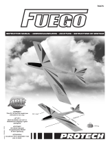
microJET
Building instructions
microJET
Caution!
Radio-controlled models, and especially model aircraft, are by no means playthings. Building and
operating them safely requires a certain level of technical competence and manual skill, together with
discipline and a responsible attitude at the flying field. Errors and carelessness in building and flying
the model can result in serious personal injury and damage to property. Since we, as manufacturers,
have no control over the construction, maintenance and operation of our products, we are obliged to
take this opportunity to point out these hazards, and to emphasise your personal responsibility.
Additional items required:
RC system components: Function
MULTIPLEX PiCO 5/6 receiver 35 MHz Order No. 5 5920
40 MHz Order No. 5 5921
MULTIPLEX Nano-S servo (2 reqd.) Elevator / aileron Order No. 6 5120
PiCO-Control 400 round UNI Speed controller Order No. 7 2292
Flight battery:
MULTIPLEX 7/500 AR - HS flight battery Order No. 15 5648
Battery charger:
PiCO AUTO-charger for rapid-charging transmitter and flight packs Order No. 9 2526
Adhesive:
MULTIPLEX “Medium Zacki” Order No. 59 2720
MULTIPLEX “Zacki Activator” Order No. 59 2824
Other types of cyano (cyano-acrylate adhesive) can be used. Do not use styrofoam cyano.
Tools:
Scissors, combination pliers, balsa knife, screwdriver, 4-5 mm Ø bradawl, small round file
Specification:
Wingspan 580 mm
Fuselage length 545 mm
All-up weight standard - 400 motor / 7 cells approx. 450 g
All-up weight 480 motor / 8 cells approx. 530 g
Wing area approx. 10.2 dm²
Wing loading min. approx. 45 g/ dm²
RC functions Aileron, elevator and motor
Separate the illustration pages from the centre of this booklet.

9
Important note
This model is not made of styrofoam™!
It is not possible to glue the material using white
glue or epoxy. Please be sure to use cyano-
acrylate glue exclusively, preferably in conjunction
with cyano activator (kicker).
fuselage and allow it to air-dry. Apply Medium Zacki to
the canopy latch retainers 22 and install them as shown
in Figs. 6+7.
6. Cut the vacuum-moulded bottom fairing 6 to size
and trim it to fit. Spray activator on the underside of the
front part of the fuselage and allow it to air-dry. Apply
Medium Zacki to the bottom fairing 6 and place it on the
fuselage. Fig. 8
7. Installing the servos
The model is designed for MULTIPLEX Nano-S servos.
Each servo lead has to be soldered directly to a servo
extension lead with separation filter # 8 5255. The
extension leads are prepared as follows:
Loop the servo extension lead through the ferrite ring eight
times; when you have finished, the distance from the ring
to the receiver should be 5 to 10 cm. Starting from inside
the fuselage, run the cable through the pierced hole in
the fuselage side in the direction of the servo well. Make
a hook from wire or a paper clip to help you pull the servo
leads through the foam. Solder the wires together, taking
care to maintain the colour coding, and insulate each joint
with a piece of heat-shrink sleeving. Now temporarily
switch on the RC system and centre the sticks and trims,
so that you can be sure that the servo output arms are at
neutral.
Shrink a piece of heat-shrink sleeving round each servo,
or wrap the servos in tape.
The tape or sleeving prevents glue penetrating into
the servo case - and especially into the gears - when
the servos are glued in place.
Now apply Zacki activator to the prepared servo, and allow
it to air-dry. Apply an adequate quantity (but not too much)
of Medium Zacki to the servo well, but only in the area
where the tape or sleeve round the servo will make
contact. Place the servo in the servo well, then run the
cable along the cable duct. If necessary, apply clear tape
over the top of the ducts to prevent the wires slipping out.
Figs. 9+10
Connect the pre-formed end of the pushrods 30 to the
outermost hole in the servo output arm. You may wish to
use one hole further inboard if you prefer your models
less “hot”. At the elevon end slip the pushrod through the
pushrod connector 25 and tighten the M3 socket-head
screw 28 using the allen key 29. Check that the elevons
are at neutral before you tighten the screws.
Trim the servo well covers 7 to fit over the servos on each
side. Fix them in place using a little Medium Zacki, or -
better - short strips of clear adhesive tape, as this provides
access to the servos for maintenance. Fig. 11
8. Installing and securing the motor
Trim the vacuum-moulded motor mount 8 to fit and glue it
to the fuselage using Medium Zacki Fig. 12. Position the
motor and secure it using the cable ties 31. Slot the cable
1. Before you start building
Check the contents of your kit.
You will find Fig. 1 and the parts list helpful here.
Assembling the model:
2. Preparing the wiring
This stage varies according to the version of the kit you
are building. In the standard version the motor must be
suppressed by fitting three capacitors 38, as shown in
Fig. 2. If you are using the MPX 400 round controller,
additional suppression measures are not necessary.
3. Forming the cable tunnels in the fuselage
Using a small bradawl or a screwdriver, push holes
through the fuselage sides to accept the cables. This is
done by laying the model on its back and twisting the
bradawl through the foam, starting from the inboard end
of the cable duct. Remove loose foam particles. Fig. 3
4. Further preparation
Prepare the glue-fitting horns 24 for installation in the
control surfaces.
There are two variants depending on the accessory pack
in your kit:
1. Pushrod connector Fig. 4
2. Articulated pushrod connector Fig. 5
Variant 1), see Fig. 4
Fit the pushrod connector 25 in the innermost 2.5 mm Ø
hole in the horn, and secure it with the washer 26 and nut
27.
Caution: Apply a drop of paint or cyano to the nuts to
prevent them working loose. Use a pin to apply the
adhesive to avoid it jamming the pivot.
Fit the socket-head grubscrew 28 in the connector.
Variant 2), see Fig. 5
Fix the articulated pushrod connector 25 to the innermost
hole in the horn using the M1.6 x 4 mm countersunk screw
27. Tighten the screw to the point where the pushrod
connector still just rotates freely, but does not wobble. Fit
the socket-head grubscrew 28 in the pushrod clamp 26,
and snap the clamp 26 into place.
Spray the horns 24 with Zacki activator and allow it to air-
dry. Apply Medium Zacki to the horn recesses, and press
the horns into place. Allow the glue to set hard.
Caution: pushing the horns into place may cause glue to
squirt out - wear goggles to be on the safe side!
5. Fitting the canopy latch retainers
Spray activator on the appropriate areas inside the

10
tie latches down into the foam adjacent to the motor mount.
Fig. 13
9. Connecting the motor
The next step is to deploy the motor power leads in the
fuselage; the arrangement varies according to the type
of controller you are using - “round” version mounted on
the motor, or a separate unit.
Since the motor is in the “pusher” configuration it must
be connected with reversed polarity, i.e. negative wire to
red spot on the motor, positive to black.
Caution!
Always reverse the motor between the speed
controller and the motor - not between the battery
and the speed controller (it’s easily done - and it
wrecks the controller!)
The Micro-Jet’s propeller 35 also operates in pusher
mode, so it must be turned round inside the spinner, i.e.
the plain side (no inscription) of the propeller should face
the motor. Fix the propeller to the motor shaft using 5-
minute epoxy or UHU Endfest 300 (slow-setting epoxy).
On no account use cyano for this!!! It makes the plastic
brittle, and the spinner will fall off!
Using a pin, apply a
little adhesive to the inside of the
hole in the plastic spinner and push the propeller onto
the motor shaft. Pierce a hole through the spinner from
the rear, again using a pin, so that trapped air can escape.
10. Completing the top of the fuselage
Trim the vacuum-moulded motor cowl 9 to fit. Glue it in
place using Medium Zacki, or - better - short strips of
clear adhesive tape, to allow access to the motor for
maintenance. Figs. 14+15
Position the canopy 2 and the turtle deck 3 on the fuselage
together with the motor cowl 9, and mark the position of
the parts. Engage the latch lugs 23 in the latch retainers
22. Apply a very small amount of Medium Zacki in the
slots in the canopy 2 and immediately press it down onto
the latch lugs. Figs. 16+17
Caution:
If you use too much glue you will have a problem …
The canopy will be closed for eternity!
11. Installing the fins
Check that the fins 4+5 are a close fit “dry”, i.e. without
glue. If the joint surfaces do not match the profile of the
wing perfectly, remove any rough edges and sand slightly
to obtain a good fit. You will probably need to remove
some moulding “flash”. Spray the joint surfaces with Zacki
activator and allow it to air-dry. Apply Medium Zacki to
the fin recesses in the top surface of the wing, and push
the fins into place. Check alignment immediately, and tape
the fins in place until the glue has cured.
Fig. 18
12. Final assembly
Glue strips of Velcro tape (hook side) 20 in the appropriate
positions on the inside of the fuselage, and attach the
loop side of the Velcro tape 21 to the corresponding
components which are to be held in place.
The RC system and power system components should
be positioned as follows:
Fuselage in the nose, followed by the flight battery and
speed controller.
The exact position of the flight pack cannot be established
at this stage, as it determines the model’s balance point.
If you find that the Velcro tape does not hold the battery
securely, fit a wedge to jam it against the fuselage turtle
deck.
Check that the battery is securely fixed
before every flight!
Run the receiver aerial through the pierced hole in the
fuselage side and along the channel in the wing. Secure
it with adhesive tape.
The next step is to test the working systems, and this
requires all the electrical connections to be completed.
Never connect the motors until you have switched
on the transmitter, and have checked carefully that
the motor control stick is at “OFF”.
Connect the servo plugs to the receiver. Switch on the
transmitter, check motor “OFF”, then connect the flight
pack to the speed controller, and the speed controller to
the receiver. Your speed controller must feature a BEC
facility, i.e. an integral receiver power supply drawing
current from the flight battery.
Switch on the motor briefly and check the direction of
rotation of the propeller. Hold the model securely while
you do this, and remove any loose, lightweight objects
behind the model before the propeller does it for you.
Caution: even small motors and propellers are
capable of causing injury!
Once you have found a space for everything, the final
task is to glue the fuselage turtle deck 3 in place. Trial-fit
the moulding in conjunction with the canopy, and trim if
necessary to obtain a close fit. Spray Zacki activator on
the turtle deck and allow it to air-dry. Apply Medium Zacki
to the joint areas of the fuselage, then press the turtle
deck into place. Take care not to glue the deck to the
motor cowl or the canopy. Fig. 19
13. Elevon travels
The travel of the elevons must be set correctly to achieve
a balanced control response. When elevator is applied
(forward / back stick), both elevons should rise by about
12 mm when you pull the stick back, and fall by about 10
mm when you move the stick forward. Aileron travel should
be +/- 5 mm, i.e. there should be no differential. If you
like (and can fly) your models “hot”, increase elevator
and aileron movement by 2 - 3 mm. Measure these travels

11
at the widest point of the elevons. If you cannot achieve
these values by adjusting your radio control system, you
will need to adjust the mechanical linkages.
For the first flight the neutral setting of the elevons
should be about 2 mm “up”. For normal flying you will
generally need to use down-trim. After the first landing
mark the trimmed elevon positions on the fins using a
waterproof felt-tip pen. We recommend that you adjust
the elevator trim before each flight, setting the elevons
about 1 mm above the marked points. Once the model
has climbed to a safe height, apply down-trim again for
the rest of the flight.
14. Balancing
The Micro-Jet, like any other aircraft, must be balanced
at a particular point in order to achieve stable flying
characteristics. Assemble your model, ready to fly, and
install the flight battery. You will find moulded-in marks
on the underside of the wing roots, close to the hand-grip
recesses. Support the model at this point on two fingertips,
and it should balance level. If it does not, you can move
the flight battery forward or aft to correct the balance point.
Once the correct position is found, mark the battery cradle
inside the model to ensure that the pack is always
replaced in the same position.
15. Gilding the lily - applying a little decoration
The kit is supplied with a multi-colour decal sheet 11. Cut
out the individual name placards and emblems and apply
them to the model in the position shown in the kit box
illustration, or in an arrangement which you find pleasing.
The cabin can be coloured using a black waterproof felt-
tip pen, continuing the colour down to the edge.
16. Preparing for the first flight
For the first flight wait for a day with as little breeze as
possible. The early evening is often a good time.
Be sure to carry out a range check before the first
flight.
Just before the flight, charge up the transmitter battery
and the flight pack using the recommended procedures.
Ensure that “your” channel is not already in use before
you switch on the transmitter.
Ask your assistant to walk away from the model, holding
the transmitter. The aerial should be fitted but completely
collapsed.
Your assistant should operate one of the functions
constantly while you watch the servos. The non-controlled
servo should stay motionless up to a range of about 60
m, and the controlled one should follow the stick
movements smoothly and without any delay. Please note
that this check can only give reliable results if the radio
band is clear of interference, and if no other radio control
transmitters are in use - even on other channels. If the
range check is successful, repeat it with the motor
running. There should be only a very slight reduction in
effective radio range with the motor turning.
If you are not sure about anything, please don’t risk a
flight. Send the whole system (including battery, switch
harness and servos) to the service department of your
RC system manufacturer and ask them to check it.
The first flight ...
Don’t try unpowered test-glides with this model!
The Micro-Jet is designed for hand-launching, and should
always be launched exactly into any wind.
If you are a beginner to model flying we strongly
recommend that you ask an experienced model pilot
to help you for the first few flights.
Allow the model to climb to a safe height, then adjust the
trim sliders on the transmitter until it flies in a perfectly
straight line “hands off”.
While the model is still at a safe altitude, switch off the
motors and try out the controls on the glide. Carry out a
“dry run” landing approach at a safe height, so that you
are prepared for the real landing when the battery runs
flat.
Don’t try any tight turns at first, and especially not on the
landing approach at low altitude. It is always better to
land safely at some distance from you, than to force the
model back to your feet and risk a heavy landing.
17. Safety
Safety is the First Commandment when flying any model
aircraft. Third party insurance should be considered a
basic essential. If you join a model club suitable cover
will usually be available through the organisation. It is
your personal responsibility to ensure that your insurance
is adequate (i.e. that its cover includes powered model
aircraft).
Make it your job to keep your models and your radio
control system in perfect order at all times. Check the
correct charging procedure for the NC batteries used in
your RC set. Make use of all sensible safety systems and
precautions which are advised for your system. An
excellent source of practical accessories is the
MULTIPLEX main catalogue, as our products are
designed and manufactured exclusively by practising
modellers for other practising modellers.
Always fly with a responsible attitude. You may think that
flying low over other people’s heads is proof of your
piloting skill; others know better. The real expert does
not need to prove himself in such childish ways. Let other
pilots know that this is what you think too. Always fly in
such a way that you do not endanger yourself or others.
Bear in mind that even the best RC system in the world is
subject to outside interference. No matter how many years
of accident-free flying you have under your belt, you have
no idea what will happen in the next minute.
We - the MULTIPLEX team - hope you have many hours
of pleasure building and flying your new model.
MULTIPLEX Modellsport
Klaus Michler
Product development

12
Parts list Micro-Jet
Part No. Description Material Dimensions
No. off
1 1 Wing Elapor foam Ready made
2 1 Canopy Elapor foam Ready made
3 1 Fuselage turtle deck Elapor foam Ready made
4 1 Left fin Elapor foam Ready made
5 1 Right fin Elapor foam Ready made
6 1 Fuselage bottom fairing Elapor foam Ready made
7 1 Pair of servo well covers Vac. moulded plastic Ready made
8 1 Motor mount Vac. moulded plastic Ready made
9 1 Motor cowl Vac. moulded plastic Ready made
10 1 Building instructions A4 format
11 1 Decal set Printed adhesive film Ready made
Accessories
20 3 Velcro tape, hook side Plastic 25 x 60 mm
21 3 Velcro tape, loop side Plastic 25 x 60 mm
22 2 Canopy latch retainer Inj. moulded plastic Ready made
23 2 Canopy latch lug Inj. moulded plastic Ready made
24 2 Glue-fitting horn Plastic Ready made
25 2 Pushrod connector Metal Ready made, 6 mm Ø
26 2 Washer Metal M2
27 2 Nut Metal M2
28 2 Pushrod connector grubscrew Metal M3
29 1 Allen key Metal 1.5 mm A/F
30 2 Pre-formed pushrod Metal Ready made, 1 mm Ø
31 2 Cable tie Plastic Ready made
Power system and small parts
35 1 Propeller Plastic 125 x 110 mm
36 1 Motor Permax 400 6V Ready made
37 1 Power cables, with green connectors Ready made
38 1 Suppressor capacitor set
/