8
Step 4 — Startup
POWERXL DG1 SERIES ADJUSTABLE FREQUENCY DRIVES MN040012EN—December 2017 www.eaton.com
Startup wizard
In the Startup Wizard, you will be prompted for essential
information needed by the drive so that it can start
controlling your process. In the Wizard, you will need the
following keypad buttons:
Chapter 4—Startup
PowerXL DG1 Series Adjustable Frequency Drives MN040004EN—April 2015 www.eaton.com 27
Startup Wizard
In the Startup Wizard, you will be prompted for essential
information needed by the drive so that it can start
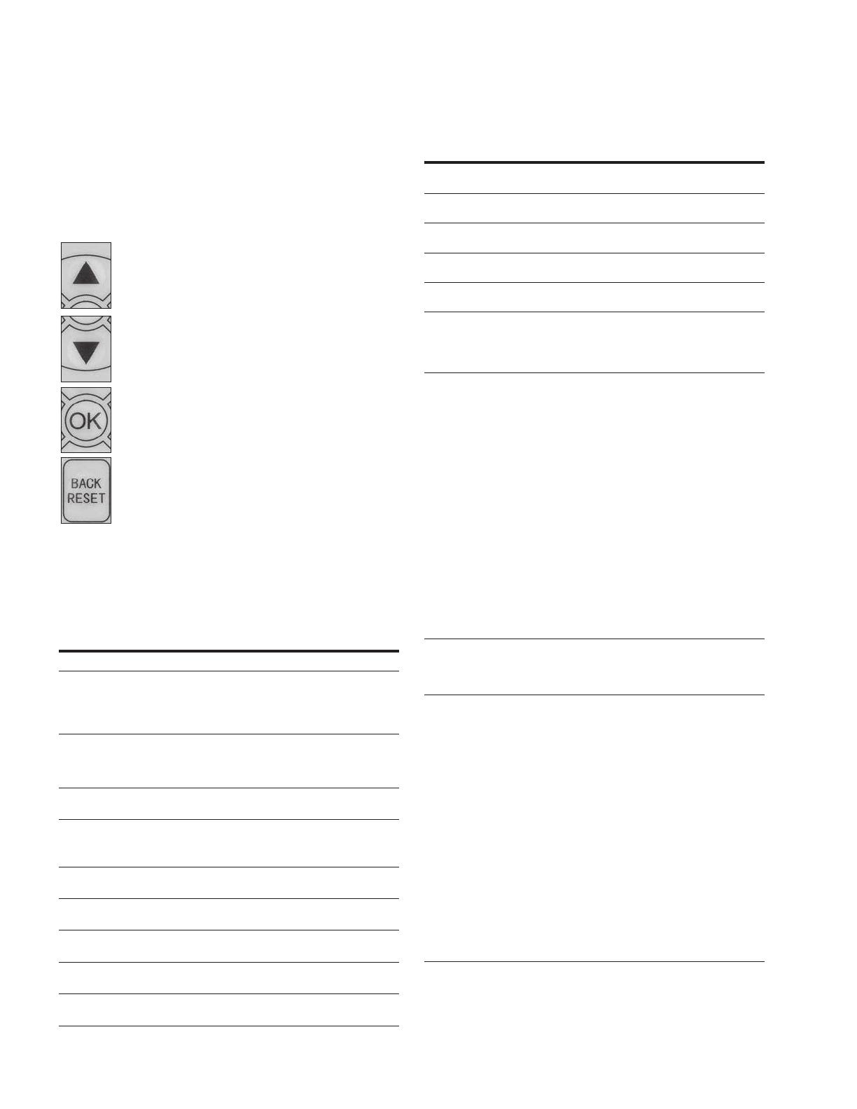
controlling your process. In the Wizard, you will need
the following keypad buttons:
Up/Down buttons.
Use these to change value.
OK button.
Confirm selection with this
next question.
Back/Reset button.
If this button was pressed at the first question,
the Startup Wizard will be cancelled.
If this button is pressed
in any step on the Startup
Wizard, the Startup Wizard will be cancelled.
Once you have connected power to your Eaton PowerXL
DG1 frequency converter, and the Startup Wizard is enabled,
follow these instructions to easily set up your drive.
Now the Startup Wizard is done. It will not show again at the
next power up. If you want to reset it, please select it from
the main menu (“Startup Wizard”).
Table 12. Startup Wizard Instructions
Item Description
1 Startup Wizard Press OK?
2 Language 0 = English
1 = ѝ᮷
2 = Deutsch
3 Real Time Clock yy.mm.dd
hh:mm:ss
4 Daylight Saving 0 = Off
1 = EU
2 = US
5 Application 0 = Standard
1 = Multi-Pump
2 = Multi-PID
3 = Multi-Purpose
6 Min Frequency Min: 0.00Hz
Max: Max Frequency
7 Max Frequency Min: Min Frequency
Max: 400.00Hz
8 Motor Nom Current Min: 0.1A
Max: 500.0A
9 Current Limit Min: Ih*1/10
Max: Ih*2
10 Motor Nom Speed Min: Ih*1/10
Max: Ih*2
11 Motor PF Min: 0.30
Max: 1.0
12 Motor Nom Volt Min: 180 V
Max: 690 V
13 Motor Nom Freq Min: 30.00 Hz
Max: 400.00 Hz
14 Accel Time 1 Min: 0.1 s
Max: 3000.0 s
15 Decel Time 1 Min: 0.1 s
Max: 3000.0 s
16 Local Control Place 0 = Keypad
1 = I/O terminal Start 1
2 = I/O terminal 2
3 = Fieldbus
17 Local Reference 0 = AI1
1 = AI2
2 = Slot A: AI1
3 = Slot B: AI1
4 = AI1 Joystick
5 = AI2 Joystick
6 = Keypad
7 = Fieldbus Ref
8 = Motor Pot
9 = Max Frequency
10 = AI1 + AI2
11 = AI1–AI2
12 = AI2–AI1
13 = AI1 * AI2
14 = AI1 or AI2
15 = Min (AI1, AI2)
16 = PID1 Control Output
18 Remote Control Place 0 = Keypad
1 = I/O terminal Start 1
2 = I/O terminal 2
3 = Fieldbus
19 Remote Reference 0 = AI1
1 = AI2
2 = Slot A: AI1
3 = Slot B: AI1
4 = AI1 Joystick
5 = AI2 Joystick
6 = Keypad
7 = Fieldbus Ref
8 = Motor Pot
9 = Max Frequency
10 = AI1 + AI2
11 = AI1–AI2
12 = AI2–AI1
13 = AI1 * AI2
14 = AI1 or AI2
15 = Min (AI1, AI2)
16 = PID1 Control Output
Table 12. Startup Wizard Instructions, continued
Item Description
Once you have connected power to your Eaton PowerXL
frequency converter, and the Startup Wizard is enabled,
follow these instructions to easily set up your drive.
Table 5. Startup wizard instructions
Item Description
1 Startup Wizard Press OK?
2 Application 0 = Standard
1 = Multi-Pump
2 = Multi-PID
3 = Multi-Purpose
3 Language 0 = English
1 =
Chapter 4—Startup
PowerXL DG1 Series Adjustable Frequency Drives MN040004EN—April 2015 www.eaton.com 27
Startup Wizard
In the Startup Wizard, you will be prompted for essential
information needed by the drive so that it can start
controlling your process. In the Wizard, you will need
the following keypad buttons:
Up/Down buttons.
Use these to change value.
OK button.
Confirm selection with this button, and enter into
next question.
Back/Reset button.
If this button was pressed at the first question,
the Startup Wizard will be cancelled.
If this button is pressed in any step on the Startup
Wizard, the Startup Wizard will be cancelled.
Once you have connected power to your Eaton PowerXL
DG1 frequency converter, and the Startup Wizard is enabled,
follow these instructions to easily set up your drive.
Now the Startup Wizard is done. It will not show again at the
next power up. If you want to reset it, please select it from
the main menu (“Startup Wizard”).
Table 12. Startup Wizard Instructions
Item Description
1 Startup Wizard Press OK?
2 Language 0 = English
1 = ѝ᮷
2 = Deutsch
3 Real Time Clock yy.mm.dd
hh:mm:ss
4 Daylight Saving 0 = Off
1 = EU
2 = US
5 Application 0 = Standard
1 = Multi-Pump
2 = Multi-PID
3 = Multi-Purpose
6 Min Frequency Min: 0.00Hz
Max: Max Frequency
7 Max Frequency Min: Min Frequency
Max: 400.00Hz
8 Motor Nom Current Min: 0.1A
Max: 500.0A
9 Current Limit Min: Ih*1/10
Max: Ih*2
10 Motor Nom Speed Min: Ih*1/10
Max: Ih*2
11 Motor PF Min: 0.30
Max: 1.0
12 Motor Nom Volt Min: 180 V
Max: 690 V
13 Motor Nom Freq Min: 30.00 Hz
Max: 400.00 Hz
14 Accel Time 1 Min: 0.1 s
Max: 3000.0 s
15 Decel Time 1 Min: 0.1 s
Max: 3000.0 s
16 Local Control Place 0 = Keypad
1 = I/O terminal Start 1
2 = I/O terminal 2
3 = Fieldbus
17 Local Reference 0 = AI1
1 = AI2
2 = Slot A: AI1
3 = Slot B: AI1
4 = AI1 Joystick
5 = AI2 Joystick
6 = Keypad
7 = Fieldbus Ref
8 = Motor Pot
9 = Max Frequency
10 = AI1 + AI2
11 = AI1–AI2
12 = AI2–AI1
13 = AI1 * AI2
14 = AI1 or AI2
15 = Min (AI1, AI2)
16 = PID1 Control Output
18 Remote Control Place 0 = Keypad
1 = I/O terminal Start 1
2 = I/O terminal 2
3 = Fieldbus
19 Remote Reference 0 = AI1
1 = AI2
2 = Slot A: AI1
3 = Slot B: AI1
4 = AI1 Joystick
5 = AI2 Joystick
6 = Keypad
7 = Fieldbus Ref
8 = Motor Pot
9 = Max Frequency
10 = AI1 + AI2
11 = AI1–AI2
12 = AI2–AI1
13 = AI1 * AI2
14 = AI1 or AI2
15 = Min (AI1, AI2)
16 = PID1 Control Output
Table 12. Startup Wizard Instructions, continued
Item Description
2 = Deutsch
4 Real Time Clock yy.mm.dd
hh:mm:ss
5 Daylight Saving 0 = Off
1 = EU
2 = US
6 Min Frequency Min: 0.00Hz
Max: Max Frequency
7 Max Frequency Min: Min Frequency
Max: 400.00Hz
8 Motor Nom Current Min: DriveNomCurrCT*1/10
Max: DriveNomCurrCT*2
9 Current Limit Min: Ih*1/10
Max: Ih*2
10 Motor Nom Speed Min: 300
Max: 20000
Table 5. Startup wizard instructions, continued
Item Description
11 Motor PF Min: 0.30
Max: 1.0
12 Motor Nom Volt Min: 180 V
Max: 690 V
13 Motor Nom Freq Min: 30.00 Hz
Max: 400.00 Hz
14 Accel Time 1 Min: 0.1 s
Max: 3000.0 s
15 Decel Time 1 Min: 0.1 s
Max: 3000.0 s
16 Local Control Place 0 = Keypad
1 = I/O terminal Start 1
2 = I/O Terminal Start 2
3 = Fieldbus
17 Local Reference 0 = AI1
1 = AI2
2 = Slot A: AI1
3 = Slot B: AI1
4 = AI1 Joystick
5 = AI2 Joystick
6 = Keypad
7 = Fieldbus Ref
8 = Motor Pot
9 = Max Frequency
10 = AI1 + AI2
11 = AI1 - AI2
12 = AI2 - AI1
13 = AI1 * AI2
14 = AI1 or AI2
15 = MIN(AI1,AI2)
16 = MAX(AI1,AI2)
17 = PID1 Control Output
18 = PID2 Control Output
18 Remote 1 Control Place 0 = Keypad
1 = I/O terminal Start 1
2 = I/O Terminal Start 2
3 = Fieldbus
19 Remote 1 Reference 0 = AI1
1 = AI2
2 = Slot A: AI1
3 = Slot B: AI1
4 = AI1 Joystick
5 = AI2 Joystick
6 = Keypad
7 = Fieldbus Ref
8 = Motor Pot
9 = Max Frequency
10 = AI1 + AI2
11 = AI1 - AI2
12 = AI2 - AI1
13 = AI1 * AI2
14 = AI1 or AI2
15 = MIN(AI1,AI2)
16 = MAX(AI1,AI2)
17 = PID1 Control Output
18 = PID2 Control Output
Now the Startup Wizard is done. It will not show again at
the next power up. If you want to reset it, please select it
from the main menu (“Startup Wizard”).
The PID Mini-Wizard is activated in the Quick Setup menu.
Step 4 — Startup


