
PRINTED: 6/12/19
ISO 9001 CERTIFIED
607 NW 27th Ave
Ocala, FL 34475
Phone: (352) 629-5020 or 800-533-3569
Fax: (352)-629-2902
S U I T A B L E F O R E X T E R N A L D I S T R I B U T I O N
Intelli-Tank Level 40
OPERATION MANUAL

FORM-ENG-0018 REV A 05-27-03
607 NW 27th Ave
Ocala, FL 34475
Ph: 352-629-5020 or 1-800-533-3569
Fax : 352-629-2902 or 1-800-520-3473
S U I T A B L E F O R E X T E R N A L D I S T R I B U T I O N
OPERATION MANUAL
PAGE
2 of 27
DATE
6/12/2019
PRODUCT GROUP
ITL40
P/N
118404-XX
REV
1.30
PRODUCT
Intelli-Tank Level 40
BY
AMS
MANUAL P/N:118253 PRINTED: 6/12/19
1. REVISION LOG ........................................................................................................................................... 4
2. SYSTEM OVERVIEW .................................................................................................................................. 5
2.1. SCOPE .................................................................................................................................................... 5
2.2. PART NUMBERS ........................................................................................................................................ 5
2.3. MODES OF OPERATION ............................................................................................................................. 5
3. OPERATION ................................................................................................................................................ 6
3.1. LED INDICATIONS ..................................................................................................................................... 6
3.1.1. Initial power ON indications ............................................................................................................... 6
3.1.2. Level indications ................................................................................................................................ 6
3.1.3. Error indications ................................................................................................................................. 7
3.2. MAGNETIC SWITCHES ............................................................................................................................... 8
3.3. CALIBRATION ........................................................................................................................................... 9
3.3.1. 1 Point Calibration ............................................................................................................................. 9
3.3.2. 2 Point Calibration (empty then full) .................................................................................................. 9
3.3.3. 2 Point Calibration (full then empty) .................................................................................................. 9
3.3.4. 5 Point Calibration ........................................................................................................................... 10
3.3.5. 9 Point Calibration ........................................................................................................................... 10
3.3.6. Calibration retention ........................................................................................................................ 10
3.3.7. Invalid calibration ............................................................................................................................. 10
3.3.8. Calibration incomplete ..................................................................................................................... 11
3.4. SELF TEST ............................................................................................................................................. 11
3.5. SETTING THE DIM LED LEVEL .................................................................................................................. 11
3.6. SHOW SOFTWARE VERSION, DEVICE SETTINGS, AND ERRORS.................................................................... 11
3.7. CONFIGURE THE COMMUNICATION METHOD ............................................................................................. 12
3.7.1. Configuring a display as a Master with 1-wire communications ..................................................... 12
3.7.2. Configuring a display as a Remote with 1-wire communications .................................................... 12
3.7.3. Configuring a display as a Master with CAN communications ........................................................ 12
3.7.4. Configuring a display as a Remote with CAN communications ...................................................... 12
3.8. CONFIGURE A CUSTOM MESSAGE SCROLL ................................................................................................ 13
3.9. USE THE DISPLAY REFERENCE MARK ....................................................................................................... 13
3.10. SLOSH DAMPENING FEATURE .................................................................................................................. 14
3.11. AUTOFILL .............................................................................................................................................. 15
3.11.1. Enabling the AutoFill output ........................................................................................................ 15
3.11.2. Disabling the AutoFill output ....................................................................................................... 15
3.11.3. Setting the AutoFill turn on level ................................................................................................. 15
3.11.4. Setting the AutoFill turn off level ................................................................................................. 15
4. PASSWORD LIST ..................................................................................................................................... 16
4. PASSWORD LIST CONTINUED ............................................................................................................... 17
5. INSTALLATION ......................................................................................................................................... 18
5.1. CUTOUT DIMENSIONS ............................................................................................................................. 18
5.2. OUTER BEZEL DIMENSIONS ..................................................................................................................... 18
5.3. LABEL ORIENTATION ............................................................................................................................... 19
5.4. PRESSURE SENSOR ................................................................................................................................ 19
5.4.1. Approved fluids ................................................................................................................................ 19
6. WIRING ...................................................................................................................................................... 20

FORM-ENG-0018 REV A 05-27-03
607 NW 27th Ave
Ocala, FL 34475
Ph: 352-629-5020 or 1-800-533-3569
Fax : 352-629-2902 or 1-800-520-3473
S U I T A B L E F O R E X T E R N A L D I S T R I B U T I O N
OPERATION MANUAL
PAGE
3 of 27
DATE
6/12/2019
PRODUCT GROUP
ITL40
P/N
118404-XX
REV
1.30
PRODUCT
Intelli-Tank Level 40
BY
AMS
MANUAL P/N:118253 PRINTED: 6/12/19
6.1. ITL40 CONNECTOR ................................................................................................................................ 20
6.2. PRESSURE SENSOR CONNECTOR ............................................................................................................ 20
6.3. COMMUNICATION WIRING EXAMPLES ....................................................................................................... 21
6.3.1. 1-wire method, 1 MASTER and 2 REMOTES ................................................................................. 21
6.3.2. 1-wire method, 2 MASTERS and 2 REMOTES .............................................................................. 21
6.3.3. CAN method, 1 MASTER and 2 REMOTES ................................................................................... 22
6.3.4. CAN method, 2 MASTERS and 2 REMOTES ................................................................................ 22
6.3.5. Terminating resistor requirement (CAN communication) ................................................................ 23
6.4. COMMUNICATION COMPATIBILITY WITH CLASS 1 PRODUCTS ...................................................................... 23
6.4.1. 1-wire compatibility .......................................................................................................................... 23
6.4.2. CAN compatibility ............................................................................................................................ 23
7. TROUBLESHOOTING ............................................................................................................................... 24
7.1. EVALUATION TABLE ................................................................................................................................ 24
7.2. USING THE DISPLAY TO VERIFY PRESSURE SENSOR SIGNAL VOLTAGE ........................................................ 25
8. GLOSSARY ............................................................................................................................................... 26
9. TECHNICAL DETAILS .............................................................................................................................. 27
9.1. TECHNICAL DETAILS ............................................................................................................................... 27
9.2. WEEE (WASTE OF ELECTRICAL AND ELECTRONIC EQUIPMENT) DIRECTIVE ............................................... 27
9.3. CE STATEMENT ...................................................................................................................................... 27
10. 板料信息声明 (ROHS 声明) – DECLARATION INFORMATION SHEET (ROHS DECLARATION) ........ 28
10.1. 产品中有毒和有害的物质或成份的名称和含量 – (NAMES AND CONTENTS OF THE TOXIC AND
HAZARDOUS SUBSTANCES OR ELEMENTS IN THE PRODUCTS) ............................................... 28

FORM-ENG-0018 REV A 05-27-03
607 NW 27th Ave
Ocala, FL 34475
Ph: 352-629-5020 or 1-800-533-3569
Fax : 352-629-2902 or 1-800-520-3473
S U I T A B L E F O R E X T E R N A L D I S T R I B U T I O N
OPERATION MANUAL
PAGE
4 of 27
DATE
6/12/2019
PRODUCT GROUP
ITL40
P/N
118404-XX
REV
1.30
PRODUCT
Intelli-Tank Level 40
BY
AMS
MANUAL P/N:118253 PRINTED: 6/12/19
1. Revision Log
Rev
Date
Approved
Changes
1.00
9-24-2008
AGK
Initial requirements
1.10
4-19-2012
Added details for the AutoFill output
1.20
5-01-2015
GMC
Changed part number of Transducer
1.30
6-12-2019
MH
Added passwords to turn on/off start-up text scroll

FORM-ENG-0018 REV A 05-27-03
607 NW 27th Ave
Ocala, FL 34475
Ph: 352-629-5020 or 1-800-533-3569
Fax : 352-629-2902 or 1-800-520-3473
S U I T A B L E F O R E X T E R N A L D I S T R I B U T I O N
OPERATION MANUAL
PAGE
5 of 27
DATE
6/12/2019
PRODUCT GROUP
ITL40
P/N
118404-XX
REV
1.30
PRODUCT
Intelli-Tank Level 40
BY
AMS
MANUAL P/N:118253 PRINTED: 6/12/19
2. System Overview
2.1. Scope
The Intelli-Tank Level 40 (ITL40) is designed to display a liquid’s volume to an eighth of a tank level accuracy through
180-degree viewable ultra-bright LEDs. An Intelli-Tank Level 40 set as a MASTER uses a 0-5 PSI (0-34.47 kPa,
0-0.3447 bar) pressure sensor to obtain tank level information and then relays that information along the
communication line(s) (1-Wire or CAN) to ITL40’s set as REMOTES. Multiple REMOTE units can be linked to the
MASTER tank level.
2.2. Part numbers Standard with auto fill
Tank Level Gauge C1 – p/n 118404-01 123340-01 – Red LEDs
p/n 118404-02 123340-02 – Amber LEDs
p/n 118404-03 123340-03 – Yellow LEDs
p/n 118404-04 123340-04 – Green LEDs
p/n 118404-05 123340-05 – Blue LEDs
p/n 118404-06 123340-06 – 2 Red, 2 Yellow, 2 Blue, 2 Green rows of LEDs
Labels C1 – p/n 117691 – water (blue)
p/n 117692 – foam (red)
p/n 117693 – foam (green)
Pressure Sensor C1 – p/n 200-00093 – 0 to 5 PSI (0 to 34.47 kPa, 0 to 0.3447 bar) gage
Adapter bushing C1 – p/n 102219 – ¾ to ¼ NPT
Installation Harness C1 – p/n 118485-10 – Master display, 10 feet
p/n 118485-20 – Master display, 20 feet
p/n 118485-30 – Master display, 30 feet
p/n 118485-40 – Master display, 40 feet
p/n 118695 – Remote display
Terminating resistor (CAN) C1 – p/n DT06-3S-P006
“Y” connector (CAN) C1 – p/n DT04-3P-P007
Operation Manual C1 – p/n 118253
One Page Manual C1 – p/n 118252
2.3. Modes of Operation
Master When the ITL40 display is calibrated with a proper pressure signal it automatically becomes a MASTER
display and will send tank level information along the communication line(s) (either 1-wire or CAN) to all
other REMOTE displays.
Remote ITL40 displays are initially shipped as REMOTE displays. A REMOTE display only requires power,
ground and communications line(s) (either 1-wire or CAN). The REMOTE display mimics the MASTER
display’s LEDs by reading the appropriate information on the communication line(s).

FORM-ENG-0018 REV A 05-27-03
607 NW 27th Ave
Ocala, FL 34475
Ph: 352-629-5020 or 1-800-533-3569
Fax : 352-629-2902 or 1-800-520-3473
S U I T A B L E F O R E X T E R N A L D I S T R I B U T I O N
OPERATION MANUAL
PAGE
6 of 27
DATE
6/12/2019
PRODUCT GROUP
ITL40
P/N
118404-XX
REV
1.30
PRODUCT
Intelli-Tank Level 40
BY
AMS
MANUAL P/N:118253 PRINTED: 6/12/19
3. Operation
3.1. LED indications
The ITL40 display uses 8 rows of LEDs to show the unit status, tank level indication (section 3.1.2), and error
indications (section 3.1.3).
3.1.1. Initial power ON indications
When the ITL40 is first powered up the display will…
1. Turn ON all of the LEDs then immediately cycle OFF each LED starting at the top row.
2. Display the custom scroll greeting (default is “CLASS 1”, but can be custom configured – section 3.8).
3. The LEDs will show the tank level indication (section 3.1.2) or error indication (section 3.1.3).
3.1.2. Level indications

FORM-ENG-0018 REV A 05-27-03
607 NW 27th Ave
Ocala, FL 34475
Ph: 352-629-5020 or 1-800-533-3569
Fax : 352-629-2902 or 1-800-520-3473
S U I T A B L E F O R E X T E R N A L D I S T R I B U T I O N
OPERATION MANUAL
PAGE
7 of 27
DATE
6/12/2019
PRODUCT GROUP
ITL40
P/N
118404-XX
REV
1.30
PRODUCT
Intelli-Tank Level 40
BY
AMS
MANUAL P/N:118253 PRINTED: 6/12/19
3.1.3. Error indications
Condition
Visual
Condition
Visual
Invalid calibration
“NO DATA”
REMOTE is not
receiving data from
MASTER
Incomplete
calibration
Password Error
(1)
EEPROM error
Unit type error
(2)
The display is not
configured as a
MASTER or
REMOTE
Sensor signal
voltage above 4.8V
Sensor signal
voltage below 0.4V
(1)”
“X” flashed four times.
(2)
Indicates that the unit type has erroneously changed. The two valid unit types are REMOTE and MASTER.

FORM-ENG-0018 REV A 05-27-03
607 NW 27th Ave
Ocala, FL 34475
Ph: 352-629-5020 or 1-800-533-3569
Fax : 352-629-2902 or 1-800-520-3473
S U I T A B L E F O R E X T E R N A L D I S T R I B U T I O N
OPERATION MANUAL
PAGE
8 of 27
DATE
6/12/2019
PRODUCT GROUP
ITL40
P/N
118404-XX
REV
1.30
PRODUCT
Intelli-Tank Level 40
BY
AMS
MANUAL P/N:118253 PRINTED: 6/12/19
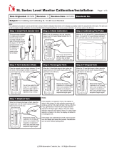
3.2. Magnetic switches
The ITL40 has two magnetic switches (left and right). The switches are activated by touching a magnet to either side
of the display in the areas shown in picture below. The label has a small “o” to indicate the location of the magnetic
switch.
For best results the magnet should be positioned over the desired switch approximately 2 inches from the front of the
display, pushed directly to the front of the display, and then pulled back to the start position (do not using a swiping
motion).
The LEDs on the display will indicate which switch was activated for approximately half a second and then the display
will go blank (LEFT = left two columns of LEDs, RIGHT = right two columns of LEDs).
LEFT (L) indication RIGHT (R) indication
The maximum time between magnetic switch activations is two seconds. If longer than two seconds have passed
between activations the unit will resume normal operation and the password attempted will be cleared.

FORM-ENG-0018 REV A 05-27-03
607 NW 27th Ave
Ocala, FL 34475
Ph: 352-629-5020 or 1-800-533-3569
Fax : 352-629-2902 or 1-800-520-3473
S U I T A B L E F O R E X T E R N A L D I S T R I B U T I O N
OPERATION MANUAL
PAGE
9 of 27
DATE
6/12/2019
PRODUCT GROUP
ITL40
P/N
118404-XX
REV
1.30
PRODUCT
Intelli-Tank Level 40
BY
AMS
MANUAL P/N:118253 PRINTED: 6/12/19
3.3. Calibration
The ITL40 display can be calibrated five different ways: 1-point (quick calibration), 2-point (level calibration) empty
then full, 2-point (level calibration) full then empty, 5-point and 9-point (volume calibration).
To enter calibration mode use a magnet and activate the magnetic switches in the order of the appropriate password.
Entering an invalid password will initiate a “password error” pattern on the display (“X”
flashed four times). The unit will then resume its normal operation and the user can
attempt to re-enter the password.
Calibrate the unit by entering the desired point calibration password –
1 point RLLR LRRL (see section 3.3.1)
2 point (empty then full) RLLR LLRL (see section 3.3.2)
2 point (full then empty) RLLR LRRR (see section 3.3.3)
5 point (start at empty) RLLR LRLR (see section 3.3.4)
9 point (start at empty) RLLR RLLR (see section 3.3.5)
During calibration, the process can be cancelled at any time by activating the LEFT magnetic switch. This will allow the
display to exit without showing an “incomplete calibration error” (section 3.1.3) on the next power cycle.
3.3.1. 1 Point Calibration
1 point calibration only calibrates the full point. The empty calibration is always set to 0.55V (approximately 1.5
inches of liquid).
1. Make certain that the tank is FULL.
2. Enter the password RLLR LRRL. The display will respond by showing the number “1”. The display will then
start normal operation with the new calibration by displaying FULL (all LEDs on).
3.3.2. 2 Point Calibration (empty then full)
1. Enter the password RLLR LLRL. The display will respond by showing the number “2”. The display will then
begin scrolling the text “SET EMPTY” across the display.
2. Make certain that the tank is EMPTY and then activate the RIGHT switch to store that point. The display will
flash the top two LED rows and then begin scrolling the text “SET FULL”.
3. Fill the tank and then activate the RIGHT switch. The display will respond by flashing the top two LED rows
and then start normal operation with the new calibration by displaying FULL (all LEDs on).
3.3.3. 2 Point Calibration (full then empty)
1. Enter the password RLLR LRRR. The display will respond by showing the number “2”. The display will then
begin scrolling the text “SET FULL” across the display.
2. Make certain that the tank is FULL and then activate the RIGHT switch to store that point. The display will
flash the top two LED rows and then begin scrolling the text “SET EMPTY”.
3. Drain the tank and then activate the RIGHT switch. The display will respond by flashing the top two LED
rows and then start normal operation with the new calibration by displaying EMPTY (cascading LEDs).

FORM-ENG-0018 REV A 05-27-03
607 NW 27th Ave
Ocala, FL 34475
Ph: 352-629-5020 or 1-800-533-3569
Fax : 352-629-2902 or 1-800-520-3473
S U I T A B L E F O R E X T E R N A L D I S T R I B U T I O N
OPERATION MANUAL
PAGE
10 of 27
DATE
6/12/2019
PRODUCT GROUP
ITL40
P/N
118404-XX
REV
1.30
PRODUCT
Intelli-Tank Level 40
BY
AMS
MANUAL P/N:118253 PRINTED: 6/12/19
3.3.4. 5 Point Calibration
1. Enter the password RLLR LRLR. The display will respond by showing the number “5”. The display will then
begin scrolling the text “SET EMPTY”.
2. Make certain that the tank is EMPTY and then activate the RIGHT switch to store that point. The display will
flash the top two LED rows and then begin scrolling the text “SET 1/4".
3. Fill the tank to the one-quarter tank point and then activate the RIGHT switch. The display will flash the top
two LED rows and then begin scrolling the text “SET 1/2".
4. Fill the tank to the one-half tank point and then activate the RIGHT switch. The display will flash the top two
LED rows and then begin scrolling the text “SET 3/4".
5. Fill the tank to the three-quarter tank point and then activate the RIGHT switch. The display will flash the top
two LED rows and then begin scrolling the text “SET FULL".
6. Fill the tank to the full point and then activate the RIGHT switch. The display will respond by flashing the top
two LED rows and then start normal operation with the new calibration by displaying FULL (all LEDs on).
3.3.5. 9 Point Calibration
1. Enter the password RLLR RLLR. The display will respond by showing the number “9”. The display will then
begin scrolling the text “SET EMPTY”.
2. Make certain that the tank is EMPTY and then activate the RIGHT switch to store that point. The display will
flash the top two LED rows and then begin scrolling the text “SET 1/8".
3. Fill the tank to the one-eighth point and then activate the RIGHT switch. The display will flash the top two
LED rows and then begin scrolling the text “SET 1/4".
4. Fill the tank to the one-quarter point and then activate the RIGHT switch. The display will flash the top two
LED rows and then begin scrolling the text “SET 3/8".
5. Fill the tank to the three-eighths point and then activate the RIGHT switch. The display will flash the top two
LED rows and then begin scrolling the text “SET 1/2".
6. Fill the tank to the one-half point and then activate the RIGHT switch. The display will flash the top two LED
rows and then begin scrolling the text “SET 5/8".
7. Fill the tank to the five-eighths point and then activate the RIGHT switch. The display will flash the top two
LED rows and then begin scrolling the text “SET 3/4".
8. Fill the tank to the three-quarter point and then activate the RIGHT switch. The display will flash the top two
LED rows and then begin scrolling the text “SET 7/8".
9. Fill the tank to the seven-eighths point and then activate the RIGHT switch. The display will flash the top two
LED rows and then begin scrolling the text “SET FULL".
10. Fill the tank to the full point and then activate the RIGHT switch. The display will respond by flashing the top
two LED rows and then start normal operation with the new calibration by displaying FULL (all LEDs on).
3.3.6. Calibration retention
Calibration data is saved in non-volatile memory (EEPROM) and the display does not need power to retain
calibration data.
3.3.7. Invalid calibration
Calibration automatically makes the ITL40 a MASTER display if the calibration is valid. An invalid calibration is
determined when any calibrated point is not at a higher level than the previous calibrated point, or if the sensor
voltage falls outside of the valid minimum (0.4V) or maximum (4.8V) range.
An invalid calibration is acknowledged by flashing “X” four times and then scrolling the text “CHECK SENSOR
VOLTS” followed by a continuous scroll of the voltage detected on the sensor’s signal (pin 6).

FORM-ENG-0018 REV A 05-27-03
607 NW 27th Ave
Ocala, FL 34475
Ph: 352-629-5020 or 1-800-533-3569
Fax : 352-629-2902 or 1-800-520-3473
S U I T A B L E F O R E X T E R N A L D I S T R I B U T I O N
OPERATION MANUAL
PAGE
11 of 27
DATE
6/12/2019
PRODUCT GROUP
ITL40
P/N
118404-XX
REV
1.30
PRODUCT
Intelli-Tank Level 40
BY
AMS
MANUAL P/N:118253 PRINTED: 6/12/19
3.3.8. Calibration incomplete
If the calibration is not completed the display will continually flash the “incomplete calibration” error (section 3.1.3),
during all subsequent power cycles. This indicates that a calibration was attempted but never completed.
Recalibrate the display completely to remove this error condition.
3.4. Self test
The ITL40 can check its hardware for proper operation by entering the password RLLR LLRR.
The display will turn all the LEDs ON and then cycle each LED OFF individually starting with the top LED. All LEDs
will come on and begin flashing between full bright and the calibrated dim level for 5 seconds. The display will then
scroll text indicating the self test condition.
Memory test
“MEM-PASS” Memory (EEPROM) is good.
“MEM-FAIL” Memory (EEPROM) failure detected.
Sensor signal test (MASTER unit only)
“SIG-PASS” Sensor signal voltage within tolerance (0.4 volts to 4.8 volts).
“SIG-FAIL” Sensor signal voltage out of tolerance (0.4 volts to 4.8 volts).
Communication wire test
‘WIRE-PASS” Data communication lines good.
“WIRE-FAIL” Data communication lines shorted or open.
If the self test password is used on a MASTER display all REMOTE displays will also perform their self test.
3.5. Setting the dim LED level
The display can be dimmed by applying system power to pin 4 (Dim Display input). The ITL40 has 9 levels of
brightness available (9 = brightest, 1 = dimmest, default value is 3).
To select the dim level of the display use the magnetic switches to enter the password RLLR LLLR.
All of the LEDs will be illuminated during the set-up. Touch a magnet against the RIGHT switch and the display will
dim to the next level and show the dim value number (9 through 1). Release the magnet and again touch it against
the RIGHT switch again to drop to the next dim level. Once the dim level is at the dimmest setting (1) the next touch
of the magnet will cycle to the highest dim level (9).
When the dim level is at the desired point activate the LEFT switch to save and exit.
3.6. Show software version, device settings, and errors
The ITL40 can display its setting by entering the password RRRR RRRR.
The display will scroll the software version, unit type, communication method, and then display any errors.
Software version
“Vx.x” Where x.x equals the numeric software version. For example, V1.0.
Unit type
“MASTER” The unit is set as a MASTER.
“REMOTE” The unit is set as a remote.
“CAL INCOMPLETE” A calibration was started but never completed.
“UNKNOWN” The unit type cannot be determined – ERROR.

FORM-ENG-0018 REV A 05-27-03
607 NW 27th Ave
Ocala, FL 34475
Ph: 352-629-5020 or 1-800-533-3569
Fax : 352-629-2902 or 1-800-520-3473
S U I T A B L E F O R E X T E R N A L D I S T R I B U T I O N
OPERATION MANUAL
PAGE
12 of 27
DATE
6/12/2019
PRODUCT GROUP
ITL40
P/N
118404-XX
REV
1.30
PRODUCT
Intelli-Tank Level 40
BY
AMS
MANUAL P/N:118253 PRINTED: 6/12/19
Communication method
“1-WIRE” Using 1-wire communication method.
“CAN” Using CAN communication method.
CAN device address (if communication method = CAN)
“ADDR=1” The unit ‘s CAN address is 1 (0xCB).
“ADDR=2” The unit ‘s CAN address is 2 (0xCC).
“ADDR=3” The unit ‘s CAN address is 3 (0xCD).
“ADDR=4” The unit ‘s CAN address is 4 (0xCE).
“ADDR=PCM” The unit ‘s CAN address is Pump Control Module (0xCA).
Error indications
“NO ERRORS” No errors detected.
“MEM-ERROR” Memory error detected.
“CAL-ERROR” Validation of calibration problem detected.
“NO-COMM” Not receiving communication from MASTER display.
“SIG-HIGH” Sensor signal voltage too high (greater than 4.8V).
“SIG-LOW” Sensor signal voltage too low (less than 0.4V).
“CAL NOT FINISHED” Calibration was started but not completed.
“TYPE-BAD” Unit type cannot be determined (not MASTER, REMOTE, or CAL INCOMPLETE).
3.7. Configure the communication method
A MASTER display can communicate to other displays that are configured as remotes via CAN or 1-wire.
The 1-wire communication method is the default method and will work with ITL40 and ITL displays.
The CAN communication method is new for the ITL40 displays and is a more robust communication method. This
method requires two wires (CAN high, CAN low) and approved J1939 CAN wiring and connectors. There should be
two (2) 120 ohm terminating resistors located at the ends of the CAN bus (see section 6.3.5).
3.7.1. Configuring a display as a Master with 1-wire communications
Enter the password LRLL LLLR to set the communication method to 1-wire. If the display was not previously a
MASTER display, calibrate the display (see section 3.3).
3.7.2. Configuring a display as a Remote with 1-wire communications
Enter the password LRLL LLLR to set the communication method to 1-wire. If the display is a MASTER display,
enter the password LRLR LRLR to turn the display into a REMOTE.
3.7.3. Configuring a display as a Master with CAN communications
Enter the password LRLL LLRL to set the communication method to CAN. If the display was not previously a
MASTER display, calibrate the display (see section 3.3).
Choose the CAN identification address to use (either address 1, 2, 3, 4, or PCM) and enter the appropriate
password to set the address (LRRR LLLL address 1, LRRR LLLR address 2, LRRR LRRR address 3,
LRRR RLLR address 4, LRRR LRLR address PCM). All REMOTE displays that are to mimic this Master display
must have their addresses matching the MASTER’s.
3.7.4. Configuring a display as a Remote with CAN communications
Choose the CAN identification address to use (either address 1, 2, 3, 4, or PCM) and enter the appropriate
password to set the address (LRRR LLRL address 1, LRRR LLRR address 2, LRRR LRRL address 3,

FORM-ENG-0018 REV A 05-27-03
607 NW 27th Ave
Ocala, FL 34475
Ph: 352-629-5020 or 1-800-533-3569
Fax : 352-629-2902 or 1-800-520-3473
S U I T A B L E F O R E X T E R N A L D I S T R I B U T I O N
OPERATION MANUAL
PAGE
13 of 27
DATE
6/12/2019
PRODUCT GROUP
ITL40
P/N
118404-XX
REV
1.30
PRODUCT
Intelli-Tank Level 40
BY
AMS
MANUAL P/N:118253 PRINTED: 6/12/19
LRRR RLLL address 4). All REMOTE displays that are to mimic the MASTER display must have their addresses
matching the MASTER’s.
The display can also be configured to mimic a Class 1 Pump Sensor Module (p/n 111097) by entering the
password for the desired tank (LRRR LRLL PCM tank 1, LRRR RLRL PCM tank 2, LRRR RLRR PCM tank 3).
3.8. Configure a custom message scroll
The ITL40 scrolls a custom message during start-up. The default scroll text is “Class 1” but the text can be custom
configured to a desired message (maximum of 21 characters allowed).
List of available characters.
A
B
C
D
E
F
G
H
I
J
K
L
M
N
O
P
Q
R
S
T
U
V
W
X
Y
Z
SP
0
1
2
3
4
5
6
7
8
9
+
-
/
=
?
.
Enter the password LLLL LRLR and the display will show the first available character - “A”.
Use the LEFT and RIGHT magnetic switches to enter the desired text.
• The LEFT magnetic switch changes the character. Each LEFT switch activation moves forward or backward
through the available characters. Wait two seconds between switch activations and the direction reverses.
• The RIGHT magnetic switch saves the displayed character to memory.
There are three methods of exiting…
• Save two SPACE characters in a row.
• Configure the maximum number of characters (21).
• Turn OFF power to the ITL40.
The custom message scroll can also be configured through a CAN message. Contact Class 1 for details.
3.9. Use the display reference mark
The level the ITL40 shows may be difficult to distinguish at a distance for some
viewers. The ITL40 can be configured with a reference mark at the top of the
display (single LED ON) which will help quickly determine level.
• Enter the password LLRR RRRR to turn the reference mark ON.
• Enter the password LLRR LLLL to turn the reference mark OFF.
The default for the reference mark is OFF.

FORM-ENG-0018 REV A 05-27-03
607 NW 27th Ave
Ocala, FL 34475
Ph: 352-629-5020 or 1-800-533-3569
Fax : 352-629-2902 or 1-800-520-3473
S U I T A B L E F O R E X T E R N A L D I S T R I B U T I O N
OPERATION MANUAL
PAGE
14 of 27
DATE
6/12/2019
PRODUCT GROUP
ITL40
P/N
118404-XX
REV
1.30
PRODUCT
Intelli-Tank Level 40
BY
AMS
MANUAL P/N:118253 PRINTED: 6/12/19
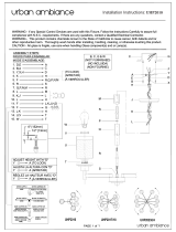
3.10. Slosh dampening feature
Some applications (off-road vehicles, etc) may submit the tank to conditions of extreme movement which causes the
fluid to slosh producing significant fluctuation in the displayed tank level.
The ITL40 can counteract these conditions by averaging the rhythmic changes (sloshing) detected by the pressure
sensor creating a more consistent displayed tank level.
Example with the slosh dampening feature DISABLED (default).
Example with the slosh dampening feature ENABLED.
• Enable the slosh dampening feature by entering the password LRRL LRRL.
The display will scroll “SLOSH ON” to indicate that the feature has been enabled.
• Disable the slosh dampening feature by entering the password LRRL LRRR.
The display will scroll “SLOSH OFF” to indicate that the feature has been disabled.

FORM-ENG-0018 REV A 05-27-03
607 NW 27th Ave
Ocala, FL 34475
Ph: 352-629-5020 or 1-800-533-3569
Fax : 352-629-2902 or 1-800-520-3473
S U I T A B L E F O R E X T E R N A L D I S T R I B U T I O N
OPERATION MANUAL
PAGE
15 of 27
DATE
6/12/2019
PRODUCT GROUP
ITL40
P/N
118404-XX
REV
1.30
PRODUCT
Intelli-Tank Level 40
BY
AMS
MANUAL P/N:118253 PRINTED: 6/12/19
3.11. AutoFill
The ITL-40 has a .250 Amp ground output driver that can be custom configured to turn on and off based on tank
levels. The feature will disable and shut off the output if the ITL-40 is in a sensor error condition once the error
condition has been resolved the output will continue to operate. (Note only available on 123340-XX units)
3.11.1. Enabling the AutoFill output
Enable the AutoFill feature by entering the password LRRL RLLL.
The display will scroll "FILL ON" to indicate that the feature has been enabled.
3.11.2. Disabling the AutoFill output
Disable the AutoFill feature by entering the password LRRL RLLR.
The display will scroll "FILL OFF" to indicate that the feature has been disabled.
3.11.3. Setting the AutoFill turn on level
The turn on level can be customized from Empty to 7/8 of a tank by entering a password (Section 4). Example if
you want the AutoFill output to turn on when the tank level falls to 1/4 of a tank or below you would enter the
following password RRRL LLRL. Once the password has been entered the display will briefly display 1/4 of a tank
to indicate the level has been set.
3.11.4. Setting the AutoFill turn off level
The turn off level can be customized from Full to 1/8 of a tank by entering a password (Section 4). Example if you
want the AutoFill output to turn off when the tank level rises to 3/4 of a tank or below you would enter the following
password RRRR LLRL. Once the password has been entered the display will briefly display 3/4 of a tank to
indicate the level has been set.

FORM-ENG-0018 REV A 05-27-03
607 NW 27th Ave
Ocala, FL 34475
Ph: 352-629-5020 or 1-800-533-3569
Fax : 352-629-2902 or 1-800-520-3473
S U I T A B L E F O R E X T E R N A L D I S T R I B U T I O N
OPERATION MANUAL
PAGE
16 of 27
DATE
6/12/2019
PRODUCT GROUP
ITL40
P/N
118404-XX
REV
1.30
PRODUCT
Intelli-Tank Level 40
BY
AMS
MANUAL P/N:118253 PRINTED: 6/12/19
4. Password list
RLLR LRRL
1 point calibration (section 3.3.1)
RLLR LLRL
2 point calibration, empty then full (section 3.3.2)
RLLR LRRR
2 point calibration, full then empty (section 3.3.4)
RLLR LRLR
5 point calibration (section 3.3.4)
RLLR RLLR
9 point calibration (section 3.3.5)
RLLR LLRR
Self test (section 3.4)
LRLR LRLR
Configure display as Remote display (section 2.3)
RLLR LLLR
Configure dim level (section 3.5)
LLRR LLRR
Display voltage (section 7.2)
LRLL LLLR
Configure for 1-wire communications (section 3.7)
LRLL LLRL
Configure for CAN communications (section 3.7)
LRRR LLLL
Configure as Master display with CAN address 1 (section 3.7.3)
LRRR LLLR
Configure as Master display with CAN address 2 (section 3.7.3)
LRRR LRRR
Configure as Master display with CAN address 3 (section 3.7.3)
LRRR RLLR
Configure as Master display with CAN address 4 (section 3.7.3)
LRRR LRLR
Configure as Master display with CAN address PCM (section 3.7.3)
LRRR LLRL
Configure as Remote display with CAN address 1 (section 3.7.4)
LRRR LLRR
Configure as Remote display with CAN address 2 (section 3.7.4)
LRRR LRRL
Configure as Remote display with CAN address 3 (section 3.7.4)
LRRR RLLL
Configure as Remote display with CAN address 4 (section 3.7.4)
LRRR LRLL
Configure as Remote display for use with Pump Sensor Module, Tank 1
(section 3.7.4)
LRRR RLRL
Configure as Remote display for use with Pump Sensor Module, Tank 2
(section 3.7.4)
LRRR RLRR
Configure as Remote display for use with Pump Sensor Module, Tank 3
(section 3.7.4)
LRRL LRRL
Slosh dampening feature enabled (section 3.10)
LRRL LRRR
Slosh dampening feature disabled (section 3.10)
LLRR LLLL
Reference mark turned OFF (section 3.9)
LLRR RRRR
Reference mark turned ON (section 3.9)
LLRR LRRL
Load defaults (remote, 1-wire, dim level 3, “CLASS 1” scroll, slosh dampening OFF)
LLLL LRLR
LLLL LRRL
LLLL LRRR
Configure custom start-up text scroll (section 3.8)
Turn off start-up text scroll
Turn on start-up text scroll (default)

FORM-ENG-0018 REV A 05-27-03
607 NW 27th Ave
Ocala, FL 34475
Ph: 352-629-5020 or 1-800-533-3569
Fax : 352-629-2902 or 1-800-520-3473
S U I T A B L E F O R E X T E R N A L D I S T R I B U T I O N
OPERATION MANUAL
PAGE
17 of 27
DATE
6/12/2019
PRODUCT GROUP
ITL40
P/N
118404-XX
REV
1.30
PRODUCT
Intelli-Tank Level 40
BY
AMS
MANUAL P/N:118253 PRINTED: 6/12/19
4. Password list continued
LRRL RLLL
AutoFill Feature enabled (section 3.8)
LLLL RLLR
AutoFill Feature Disabled (section 3.8)
RRRL LLLL
Configure AutoFill turn on for Empty (section 3.8)
RRRL LLLR
Configure AutoFill turn on for 1/8 Tank (section 3.8)
RRRL LLRL
Configure AutoFill turn on for 1/4 Tank (section 3.8)
RRRL LLRR
Configure AutoFill turn on for 3/8 Tank (section 3.8)
RRRL LRLL
Configure AutoFill turn on for 1/2 Tank (section 3.8)
RRRL LRLR
Configure AutoFill turn on for 5/8 Tank (section 3.8)
RRRL LRRL
Configure AutoFill turn on for 3/4 Tank (section 3.8)
RRRL LRRR
Configure AutoFill turn on for 7/8 Tank (section 3.8)
RRRR LLLL
Configure AutoFill turn off for Full (section 3.8)
RRRR LLLR
Configure AutoFill turn off for 7/8 Tank (section 3.8)
RRRR LLRL
Configure AutoFill turn off for 3/4 Tank (section 3.8)
RRRR LLRR
Configure AutoFill turn off for 5/8 Tank (section 3.8)
RRRR LRLL
Configure AutoFill turn off for 1/2 Tank (section 3.8)
RRRR LRLR
Configure AutoFill turn off for 3/8 Tank (section 3.8)
RRRR LRRL
Configure AutoFill turn off for 1/4 Tank (section 3.8)
RRRR LRRR
Configure AutoFill turn off for 1/8 Tank (section 3.8)

FORM-ENG-0018 REV A 05-27-03
607 NW 27th Ave
Ocala, FL 34475
Ph: 352-629-5020 or 1-800-533-3569
Fax : 352-629-2902 or 1-800-520-3473
S U I T A B L E F O R E X T E R N A L D I S T R I B U T I O N
OPERATION MANUAL
PAGE
18 of 27
DATE
6/12/2019
PRODUCT GROUP
ITL40
P/N
118404-XX
REV
1.30
PRODUCT
Intelli-Tank Level 40
BY
AMS
MANUAL P/N:118253 PRINTED: 6/12/19
5. Installation
5.1. Cutout dimensions
The display requires a cutout as shown. The display is water tight and may be mounted in any location on the
operator’s panel.
Unit of scale: inches [millimeters]
5.2. Outer bezel dimensions
Unit of scale: inches [millimeters]

FORM-ENG-0018 REV A 05-27-03
607 NW 27th Ave
Ocala, FL 34475
Ph: 352-629-5020 or 1-800-533-3569
Fax : 352-629-2902 or 1-800-520-3473
S U I T A B L E F O R E X T E R N A L D I S T R I B U T I O N
OPERATION MANUAL
PAGE
19 of 27
DATE
6/12/2019
PRODUCT GROUP
ITL40
P/N
118404-XX
REV
1.30
PRODUCT
Intelli-Tank Level 40
BY
AMS
MANUAL P/N:118253 PRINTED: 6/12/19
5.3. Label orientation
Before mounting the display and adhering the label insure that the display is situated correctly (TOP is UP). Refer to
the drawing for orientation.
p/n 117691
p/n 117692
p/n 117693
5.4. Pressure sensor
The pressure sensor (p/n 102162) is threaded for ¼” NPT and must be mounted vertically as depicted to insure an
accurate reading.
5.4.1. Approved fluids
The pressure sensor has been tested and approved for water and Class A and B foams.

FORM-ENG-0018 REV A 05-27-03
607 NW 27th Ave
Ocala, FL 34475
Ph: 352-629-5020 or 1-800-533-3569
Fax : 352-629-2902 or 1-800-520-3473
S U I T A B L E F O R E X T E R N A L D I S T R I B U T I O N
OPERATION MANUAL
PAGE
20 of 27
DATE
6/12/2019
PRODUCT GROUP
ITL40
P/N
118404-XX
REV
1.30
PRODUCT
Intelli-Tank Level 40
BY
AMS
MANUAL P/N:118253 PRINTED: 6/12/19
6. Wiring
6.1. ITL40 connector
The ITL40 has one connector and the following definitions apply:
Mating connector: Deutsch DT06-12SB BLACK
Mating sockets: Deutsch 0462-201-16141
Wedge lock: W12S Recommended wire gage: 16-18 AWG
PIN
CIRCUIT
DESCRIPTION
1
SUPPLY (+)
(INPUT) – battery voltage (+9VDC…+32VDC)
2
CAN HIGH
(DATA) – SAE J1939 CAN 2.0B, 250Kbits/s
3
CAN SHIELD
(DATA) – SAE J1939 CAN 2.0B, 250Kbits /s
4
DIM DISPLAY
(INPUT) – Dim display input (positive polarity)
5
Sensor REF
(OUTPUT) – pressure sensor supply (+5VDC)
6
Sensor SIGNAL
(INPUT) – pressure sensor signal (+0.5VDC to +4.5VDC)
7
Sensor GND
(OUTPUT) – pressure sensor ground
8
AUX Output
(OUTPUT) – ground .250 Amps (Auto Fill Version only)
9
1-WIRE SIG
(DATA) – Class 1proprietary communication
10
GROUND
(OUTPUT) – common ground
11
CAN LOW
(DATA) – SAE J1939 CAN 2.0B, 250Kbits /s
12
SUPPLY (-)
(INPUT) – battery ground
6.2. Pressure sensor connector
The pressure sensor has one connector and the following definitions apply:
Mating connector: Packard Metri-Pack 150 series, 12047909
Mating sockets: Packard Metri-Pack 150 series, 12103881
Recommended wire gage: 18-20 AWG
PIN
CIRCUIT
DESCRIPTION
A
SUPPLY (+)
(INPUT) – pressure sensor supply (+5VDC)
B
SUPPLY (-)
(INPUT) – pressure sensor ground
C
Signal
(OUTPUT) – pressure sensor signal (+0.5VDC to +4.5VDC)
Page is loading ...
Page is loading ...
Page is loading ...
Page is loading ...
Page is loading ...
Page is loading ...
Page is loading ...
Page is loading ...
-
 1
1
-
 2
2
-
 3
3
-
 4
4
-
 5
5
-
 6
6
-
 7
7
-
 8
8
-
 9
9
-
 10
10
-
 11
11
-
 12
12
-
 13
13
-
 14
14
-
 15
15
-
 16
16
-
 17
17
-
 18
18
-
 19
19
-
 20
20
-
 21
21
-
 22
22
-
 23
23
-
 24
24
-
 25
25
-
 26
26
-
 27
27
-
 28
28


HALE ITL-40 Operating instructions
- Type
- Operating instructions
- This manual is also suitable for
Ask a question and I''ll find the answer in the document
Finding information in a document is now easier with AI
Related papers


Other documents
-
 MYAO P006 Wall Charger Power Bank User manual
-
Intermec 5020 Getting Started Manual
-
 Waterous SL TANK LEVEL MONITOR SYSTEM Operating instructions
-
 Waterous SL10IC, TANK LEVEL Operating instructions
-
 urban ambiance UHP2017 Installation guide
-
 urban ambiance UHP2018 Installation guide
-
 urban ambiance UHP2023 Installation guide
-
-
AEG Food Saver 8.000.024.628 User manual
-
Hagerco 4600 Series Electrified Narrow Stile Rim - Grade 1 Electrified Narrow Stile Rim Installation guide


