Page is loading ...

MIDAS REX® MR7
Pneumatic High-Speed System
Pneumatyczny system wysokoobrotowy
Pneumatický vysokorychlostní systém
Nagy sebességĦ pneumatikus rendszer
Instruction Manual
Instrukcja obsáugi
Návod
Használati útmutató
Rx Only
PTSC224

Symbols
The following symbols may appear within this manual, on product labeling, or on the product itself:
Attention, see Instructions for Use. Tube Control
United States federal law restricts this
device to sale by or on the order of a
physician.
Air Pressure Relief
Reference Number Use with
Lot Number Multi-Use Disposable
Attachment
Serial Number Instrument Case Instrument Case
Quantity Lubricant/Diuser Lubricant/Diffuser
For single patient use only. Do not
re-use, re-process, or re-sterilize this
product. Re-use, re-processing or
re-sterilization may compromise the
structural integrity of the device and/
or create a risk of contamination of the
device, which could result in patient
injury, illness, or death.
Dissecting Tool Dissecting Tool
Approximately equal to Attachment Attachment
STERILE Non-Sterile Control Unit Control Unit
Sterilized by Gamma Irradiation Refurbished Refurbished
Use by date Accessory Accessory
Date of manufacture REGULATOR Regulator
Temperature Limitations Bone Mill Bone Mill
Unlock MOTOR Motor
Lock Brush Brush
|On Adapter Adapter
Off USA Only
+Finger-Operated Control Manufacturer
Foot-Operated Control Do not dispose to unsorted
municipal waste.
Compliant with European Council
Directive MDD 93/42/EEC. Tool Control
EC REP Authorized Representative in the
European Community Consult Instructions for Use
PTSC224

i
Contents
General Information ...........................................................................................................................1
Indications for Use .............................................................................................................................. 1
Contraindications ....................................................................................................................1
Special Notices .........................................................................................................................1
General Safety Precautions .....................................................................................................2
No Latex Policy ........................................................................................................................2
System Components ...........................................................................................................................3
Non-Disposable Components ...............................................................................................3
Disposable Components .........................................................................................................7
Legend® Dissecting Tools ........................................................................................................8
General Guidelines For Attachment and Tool Applications ..............................................9
Setting up the Operating Room ..................................................................................................... 12
Power Source Requirements ............................................................................................... 12
Pneumatic Connections....................................................................................................... 12
Setting up the MR7 System ............................................................................................................. 13
Installing the Oiler Cartridge .............................................................................................. 13
Connecting the Motor ......................................................................................................... 14
Installing an Attachment and Tool ................................................................................................ 15
Straight Attachments ............................................................................................................ 15
Specialized Attachments ...................................................................................................... 15
Activating the Motor ....................................................................................................................... 16
Disassembling the MR7 System ..................................................................................................... 17
Depressurize the System ...................................................................................................... 17
Disconnect Hoses ................................................................................................................. 17
Discard the Lubricant/Di user Cartridge ......................................................................... 17
Remove the Attachment and Tool ...................................................................................... 17
Cleaning & Sterilizing the MR7 System ........................................................................................ 18
MR7 Motor ............................................................................................................................ 18
Legend Attachments / Tubes ............................................................................................... 19
PTSC224

ii
MR7 Pneumatic Control Unit / Regulator Hose /
Triton Adapter / Instrument Case ...................................................................................... 21
Transmissible Spongiform Encephalopathies (TSE) Return Policy............................... 21
Troubleshooting ............................................................................................................................... 22
Refurbishing or Repairs .................................................................................................................. 25
Preventative Maintenance ............................................................................................................... 26
Limited Warranty ............................................................................................................................. 27
Appendix A—Specialized Attachments ........................................................................................ 28
Angled Attachments ............................................................................................................. 28
Angled Double Lock Attachments ..................................................................................... 29
Curved Bur Attachments ..................................................................................................... 30
Variable Exposure Attachments ......................................................................................... 31
Footed Attachments ............................................................................................................. 32
Rotating Footed Attachments ............................................................................................. 33
Contra-Angle Attachment (16-MF) ................................................................................... 34
Metal Cutting Attachments ................................................................................................. 35
Telescoping Attachments ..................................................................................................... 36
Perforator Driver Attachments ........................................................................................... 37
Jacobs® Chuck Attachments ................................................................................................ 38
Bone Mill Attachment .......................................................................................................... 39
PTSC224

1
General Information
General Information
Read and understand this manual before use of the MR7 System.
The Midas Rex® MR7 system is designed for use by medical professionals familiar with powered surgical instrumentation.
The surgeon is responsible for learning the proper techniques in the use of this system, as inappropriate use may potentially
be harmful. It is strongly recommended that the surgeon and dedicated operating room personnel are knowledgeable with
the use of this equipment by being trained in Medtronic Midas Rex Hands-On Workshops or by one of the local authorized
representatives.
The MR7 system consists of the following components:
• MR7 or MR7 Touch Motor
• MR7 Pneumatic Control Unit with Various Connectors
• MR7 Regulator Hose
• MR7 Lubricant/Di user Cartridge
• MR7 Triton® Adapter (optional)
• Legend® Attachments*
• Legend® Dissecting Tools*
*The MR7 system uses the same attachments and dissecting tools as the Legend® Pneumatic High-Speed System.
Indications for Use
The Medtronic Midas Rex MR7 System is a pneumatically operated surgical instrument system. The pneumatic motors
provide power to operate removable rotating surgical cutting tools and their accessories intended for use in neurosurgery,
including craniotomy and spinal surgery; as well as Ear, Nose and Throat (ENT), orthopedic and general surgical applications
including maxillofacial, craniofacial and sternotomy surgeries.
Contraindications
None
Special Notices
The words warning, caution and note have special meanings in this manual, and should be carefully reviewed:
WARNING: A warning indicates that the personal safety of the patient or physician may be involved. Disregarding this
information could result in injury to the patient or physician.
CAUTION: A caution indicates that there is a risk of damaging equipment.
NOTE: A note is intended to provide additional information, which may be useful, but is not essential to complete the
procedure.
PTSC224

2
General Information
General Safety Precautions
WARNINGS:
• Do not use the Midas Rex MR7 System before proper cleaning and sterilization.
• Do not operate the Midas Rex MR7 System in the presence of Magnetic Resonance Imaging devices.
• Do not use damaged, faulty, or modi ed Midas Rex MR7 System components. Inspect the Midas Rex MR7 System for
damage prior to each use:
• Check the motor’s exhaust hose for cracks or tears.
• Visually inspect attachments and tools. Do not use bent or damaged tools.
• Install attachment and dissecting tool, then brie y run motor.
* Check motor for overheating and leaking lubricant.
* Check attachment for overheating.
* Check dissecting tool for ail.
• Do not operate the Midas Rex MR7 System without eye protection.
• Motors and attachments which fail due to extended use may allow a component to detach and fall from the motor or
attachment, and may cause patient injury.
• Heavy side loads and/or long operating periods may cause the device to overheat. If overheating occurs:
• Never place an overheated motor on the patient or draping during surgery.
• Discontinue use and rest the motor by using intermittently, or wrap the motor/attachment interface with a moist
sterile towel.
• If the motor is passed o , the receiver should grasp the motor by the proximal end close to the motor hose.
• To avoid injury to the patient or user, do not place the handpiece on the patient or in an unsecured location, when not
in use.
• Midas Rex MR7 motors should only be operated when the attachment is in the position.
If a dissecting tool package is opened, but the tool is not used or contaminated, the tool can be re-sterilized by steam
sterilization. Remove tool from all original packaging and place into an approved autoclave package. Steam sterilize as
follows:
High Vacuum Steam: 270° F (132° C) for 5 minutes
Gravity Displacement: 270° F (132° C) for 15 minutes
The re-sterilized tool must be used promptly following re-sterilization. If rust or corrosion is encountered after
re-sterilization, do not use the re-sterilized tool.
No Latex Policy
Legend and MR7 products, packaging materials, labels, package inserts, and similar items manufactured by and/or for
Medtronic Powered Surgical Solutions (MPSS) do not contain latex.
PTSC224

3
System Components
System Components
Non-Disposable Components
MR7 Motor
The MR7 motor is a high-speed, high-torque motor used to dissect bone and biomaterials.
Figure 1: Motor Components
In addition to the components listed in Figure 1, each MR7 motor has a lubricant/di user housing at the end of the motor
hose, as seen in Figure 2.
Figure 2: Lubricant/Di user Housing
123
4
56
1. Collet
2. Motor Case
3. Swivel
4. Hose
5. Finger Control Lever
6. Safety Slide (MR7 Touch Only)
PTSC224

4
System Components
WARNING: Use only Medtronic Midas Rex Legend or MR7
devices with an MR7 motor. Use of other devices may
cause injury or damage equipment, and will void the
manufacturer’s warranty.
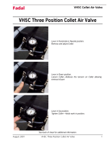
Pneumatic Control Unit
The pneumatic control unit (Figure 3) provides variable
speed motor control controls through a foot pedal. It also
allows the user to switch between nger and foot control
of the motor (if applicable).
Regulator
The regulator (Figure 4) controls the delivery pressure
of compressed gas to the pneumatic control unit. The
pressure gauges monitor cylinder pressure (right gauge)
and delivery pressure (left gauge).
Note: Outlet pressure gauge accurate to +/- 12 psi.
Instrument Case
The instrument case (Figure 5) is used to organize
equipment.
Regulator Hose
Connects from the gas source to the pneumatic control
unit to deliver compressed gas.
Figure 3: Pneumatic Control Unit
Figure 4: Regulator
Figure 5: Instrument Case
PTSC224

5
System Components
N2 DISS to Male Schrader Adapter
The N2 DISS to male Schrader adapter (Figure 6) allows
for the regulator hose to be attached to a female Schrader
in-house gas connection. A N2 DISS to female Schrader
adapter is also available for connection of the regulator
hose to a male Schrader in-house gas connection.
N2 DISS to Air DISS Adapter
The N2 DISS to air DISS adapter (Figure 7) allows for the
regulator hose to be attached to an Air DISS in-house gas
connection.
N2 DISS to WF4 Adapter
The N2 DISS to WF4 adapter (Figure 8) allows for the
regulator hose to be attached to a Midas Rex safety valve
regulator previously used for Midas Rex Classic or Midas
Rex III motors. The in-line oiler must be removed from the
safety valve regulator.
Motor Wrench
The motor wrench (Figure 9) is used to align arrows
on motor collet ats prior to installation of a Legend
attachment.
Triton Adapter
The Triton adapter (Figure 10) allows the Triton handpiece
to be driven by the MR7 pneumatic control unit. It
functions much the same way as the Triton port on
the Legend pneumatic control unit, except that it is
connected between the control unit and the gas source,
rather than being integrated into the control unit
Figure 6: N2 DISS to Male Schrader Adapter
Figure 7: N2 DISS to Air DISS Adapter
Figure 8: N2 DISS to WF4 Adapter
Figure 9: Motor Wrench
Figure 10: Triton Adapter
PTSC224

6
System Components
Legend Attachments
Legend motor attachments are available in various designs to facilitate a variety of surgical procedures. Attachments vary in
length, diameter, and overall design. They are marked and color-coded to correspond with their associated dissecting tools.
A few of the Legend attachments available are listed in the table below.
Attachment Example Other Details/Options
Standard Straight Attachments AS09
Standard Angled Attachments AA14
Straight Variable Exposure Attachments AVS07
Angled Variable Exposure Attachments AVA07
Fixed Footed Attachments AF01
Rotating Footed Attachments AF01R
Telescoping Attachments AT10 (base)
TT12A (tube)
The telescoping attachment requires the use of the AT10
attachment base, as well as a telescoping tube. Tubes are
available in straight, curved, or hooded form.
Contra-Angle AttachmentAC16
Metal Cutting AttachmentASMC
Perforator AttachmentAD01 Available in 800 RPM or 1000 RPM form.
5/32” Jacobs Chuck AttachmentAD02
Bone Mill AttachmentBM100
NOTE: Angled and straight attachments with the same length, marking, and color band share the same dissecting tool.
Curved and straight telescoping tubes with the same length, marking, and color band also share the same dissecting tool.
Example: The 14-AM straight and 14-AM angled attachments are 14 cm long, marked 14-AM and have a green color band.
All dissecting tools with the pre x 14 (14MH30) may be used in either the 14-AM straight or 14-AM angled attachment.
Be sure to match the color code and nomenclature on the Legend Dissecting Tool packaging with the color band and
nomenclature on the Legend Attachment.
PTSC224

7
System Components
Disposable Components
WARNING: Use only Medtronic Midas Rex Legend or
MR7 devices with an MR7 motor. Use of other devices
may cause injury or damage equipment, and will void
the manufacturer’s warranty.
Lubricant/Diffuser Cartridge
The lubricant/di user cartridge (Figure 11) provides
lubrication to the motor and lters oil from exhausted air.
Telescoping Tubes
Telescoping tubes (Figure 12) provide support to the
rotating dissecting tool. Telescoping tubes are disposable
following multiple uses and should be discarded when
heat or excessive vibration is noticed or insertion of tools
becomes di cult.
Cleaning Brushes
Cleaning brushes (Figure 13) are used to clean debris
from lumen of attachments and telescoping tubes. Sized
for an internal bore diameter of 3.2 mm, 2.4 mm or 1.2
mm in Legend Attachments and Telescoping Tubes.
NOTE: Cleaning brushes will not pass through angled,
contra-angle, metal cutting, perforator, or Jacobs Chuck
attachments, because they are not cannulated.
Figure 11: Lubricant/Di user Cartridge
Figure 12: Telescoping Tube
Figure 13: Cleaning Brushes
3.2mm
2.4mm
1.2mm
PTSC224

8
System Components
Legend® Dissecting Tools
Legend dissecting tools are sterile cutting tools, intended for cutting bone and biomaterials.
Dissecting Tool Nomenclature
Part numbers for Legend dissecting tools follow a standard naming convention, which is described in the diagram below.
A basic part number consists of the associated attachment length, the tool head shape, and the tool head diameter. Part
numbers may also include a variety of pre xes to identify speci c attachment types, as well as a variety of su xes to provide
additional information about the dissecting tool. Tools that use a design taken from the Mednext line are designated by an
additional “-MN” su x.
Tool Number Pre¿ xes (not all inclusive)
F... For use with footed attachments
MC For use with metal cutting attachments
TFor use with telescoping attachments
Tool Head Shapes (not all inclusive)
AC Acorn MH Match Head
BA Ball OV Oval
CY CylinderRT Reverse Taper
HM Hole MakerTA Tapered
HS Hole SawTD Twist Drill
Tool Number Suf¿ xes (note that more than one of the su xes listed may be combined in a single part number)
LLongSSpiral
DDiamond SH Short
XExtraDC Diamond Coarse
FFineDX Diamond Extra Coarse
CCarbideMN Mednext Tool Design
Associated
Attachment
Length Tool
Head Diameter
(x.x millimeters)
Optional
Pre¿ x
Optional
Suf¿ x
Tool
Head Shape
PTSC224

9
System Components
WARNINGS:
• Dissecting tools are for single-use only. Do not attempt to sterilize them. The dissecting tools are packed sterile and are
not intended for repeat use. To prevent contamination, use only once.
• Do not use an attachment and dissecting tool combination that results in tool ail or excessive vibration.
• Do not attempt to remove a tool while the motor is running.
• Do not attempt to remove a tool from an overheated motor or attachment.
• Do
not use the device if the package is opened or damaged.
General Guidelines For Attachment and Tool Applications
These are general guidelines for dissecting tool applications and are not an all-inclusive listing.
WARNING: Be sure to match the color code and nomenclature on the Legend Dissecting Tool packaging with the color
band and nomenclature on the Legend Attachment. Failure to do so could result in injury to the patient or operating room
sta .
Surgical
Application
Commonly
Used
Attachments
Commonly Used
Dissecting Tools
Suggested
Motor(s)
Spine8-B, 9-M, 14-AM,
15-A
Match Head
Elongated spherical design allows controlled, delicate
dissection. For entry hole, nerve decompression, osteophyte
removal, sinus dissection, etc.
Ball
Helical cutting utes dissect bone or cement e ectively
from a wide variety of approach angles. For debridement,
decortication, sinus dissection, etc.
Oval
Helical cutting utes and curved design blend acorn and ball
styles to vary dissection e ciency with approach angle. For
decortication, laminotomy, entry hole, nerve decompression,
osteophyte removal, etc.
Hole Maker/Saw
Matched sets of Hole Makers and Hole Saws are e cient and
e ective for interbody fusion.
Cylinder
E ective bone sculpting and planing. For graft shaping,
debridement, corpectomy, decortication, interbody fusion,
fusion takedown, etc.
Acorn
Curved design varies dissection e ciency with varied
approach angles. For entry hole, laminotomy, bone shaping,
debridement, corpectomy, decortication, fusion takedown, etc.
MR7, MR7
Touch
TelescopingMatch Head
Elongated spherical design allows controlled, delicate
dissection. For entry hole, nerve decompression, osteophyte
removal, sinus dissection, etc.
MR7, MR7
Touch
Footed, StraightTapered
Slender design for precise dissection with minimal bone loss.
For transection, osteotomy, graft harvesting, bone shaping,
entry hole, suture hole, midface advancement, etc.
PTSC224

10
System Components
Surgical
Application
Commonly
Used
Attachments
Commonly Used
Dissecting Tools
Suggested
Motor(s)
Neurosurgical–
Cranial
7-6ST, 8-B, 9-M,
10-9ST, 14-AM,
15-A
Match Head
Elongated spherical design allows controlled, delicate
dissection. For entry hole, nerve decompression, osteophyte
removal, sinus dissection, etc.
Ball
Helical cutting utes dissect bone or cement e ectively
from a wide variety of approach angles. For debridement,
decortication, sinus dissection, etc.
Twist Drill
Helical design with stop produces a hole with a precise depth.
Ideal for plating.
Acorn
Curved design varies dissection e ciency with varied
approach angles. For entry hole, laminotomy, bone shaping,
debridement, corpectomy, decortication, fusion takedown, etc.
MR7
TelescopingMatch Head
Elongated spherical design allows controlled, delicate
dissection. For entry hole, nerve decompression, osteophyte
removal, sinus dissection, etc.
FootedTapered
Slender design for precise dissection with minimal bone loss.
For transection, osteotomy, graft harvesting, bone shaping,
entry hole, suture hole, midface advancement, etc.
General
Surgery and
Plastic Surgery
(Craniofacial/
Maxillofacial/
Sternotomy)
7-6ST, 8-B, 9-M,
10-9ST, 14-AM
Match Head
Elongated spherical design allows controlled, delicate
dissection. For entry hole, nerve decompression, osteophyte
removal, sinus dissection, etc.
Ball
Helical cutting utes dissect bone or cement e ectively
from a wide variety of approach angles. For debridement,
decortication, sinus dissection, etc.
Tapered
Slender design for precise dissection with minimal bone loss.
For transection, osteotomy, graft harvesting, bone shaping,
entry hole, suture hole, midface advancement, etc.
Twist Drill
Helical design with stop produces a hole with a precise depth.
Ideal for plating.
MR7, MR7
Touch
Ear, Nose, and
Throat (Otology,
Neurootology)
7-6ST, 10-9ST Ball
Helical cutting utes dissect bone or cement e ectively
from a wide variety of approach angles. For debridement,
decortication, sinus dissection, etc.
MR7
PTSC224

11
System Components
Surgical
Application
Commonly
Used
Attachments
Commonly Used
Dissecting Tools
Suggested
Motor(s)
Orthopaedics 8-B, 9-M,
14-AM, 21-TU,
26-R, Footed,
Telescoping
Ball
Helical cutting utes dissect bone or cement e ectively
from a wide variety of approach angles. For debridement,
decortication, sinus dissection, etc.
Tapered
Slender design for precise dissection with minimal bone loss.
For transection, osteotomy, graft harvesting, bone shaping,
entry hole, suture hole, midface advancement, etc.
Acorn
Curved design varies dissection e ciency with varied
approach angles. For entry hole, laminotomy, bone shaping,
debridement, corpectomy, decortication, fusion takedown, etc.
Cylinder
E ective bone sculpting and planing. For graft shaping,
debridement, corpectomy, decortication, interbody fusion,
fusion takedown, etc.
MR7, MR7
Touch
FootedTapered
Slender design for precise dissection with minimal bone loss.
For transection, osteotomy, graft harvesting, bone shaping,
entry hole, suture hole, midface advancement, etc.
Biometals/
Bioceramics/
Biomaterials
MC Metal Cutter
Cutting utes or diamond wheel design remove metals,
ceramics and other biomaterials e ectively from a variety
of approach angles. For cutting rods, pins, plates, implants,
screws, etc.
MR7, MR7
Touch
PTSC224

12
Setting up the Operating Room
Setting up the Operating Room
Power Source Requirements
Required Operating
(Dynamic) Pressure
Nominal Operating
(Dynamic) Pressure
Approximate Flow Rate
Required
Gas Type
80–120 psi 100 psi 12 cubic feet/min. Nitrogen or Dry-Filtered
Compressed Air
5.5–8.3 bar 6.9 bar 340 liters/min.
CAUTION: Do not run the motor at an operating pressure above or below the required operating pressure range. Operating
pressure below 80 psi (5.5 bar) may not provide proper lubrication to the motor. Operating pressure above 120 psi (8.3 bar)
may damage or reduce the life of the motor.
Pneumatic Connections
Figure 14: Gas Connection Options
CAUTION: If you are using the Midas Rex Safety Valve Regulator instead of the Legend Regulator, you must replace the
in-line oiler with the DISS/WF4 adapter before use.
1. Regulator Hose (N2 DISS)
2. N2 DISS to Air DISS Adapter Gas Source
3. N2 DISS to Male Schrader Adapter Gas Source
4. Gas Source (N2 DISS)
5. Regulator
6. DISS/WF4 Adapter
7. Regulator
PTSC224

13
Setting up the MR7 System
Setting up the MR7 System
Installing the Oiler Cartridge
WARNING: Do not use the MR7 system with the Midas
Rex in-line oiler. The MR7 motor is su ciently lubricated
by the lubricant/di user on the motor hose, and will be
over-lubricated if the Midas Rex in-line oiler is used.
1. Set the non-running (static) pressure to 80–120 psi
(5.5–8.3 bar) at the gas source. Operating (dynamic)
pressure may be adjusted later.
2. Hold the lubricant/di user cartridge perpendicular
to the housing (Figure 15), and press the cartridge’s
circular tting onto the housing’s circular receptacle
(Figure 16), breaking the foil seal.
3. Rotate the cartridge down until it clicks into place.
4. Verify that the symbol on the cartridge is lined up
with the notch on the housing (Figure 17).
WARNINGS:
• Failure to properly secure the lubricant/di user
cartridge may cause injury to operator and/or
operating room sta .
• Do not attempt to remove the lubricant/di user
cartridge while the system is pressurized.
CAUTIONS:
• Do not use an MR7 motor without a lubricant/
di user installed.
• Do not use a lubricant/di user cartridge for more
than one hour of drill time.
• Do
not re-use a lubricant/di user cartridge. It is a
single-use product.
• Do not attempt to re ll a used lubricant/di user
cartridge.
• Do not use a lubricant/di user cartridge if it appears
to be damaged, or if the inner foil seal is punctured.
Figure 15: Aligning the Lubricant/Di user Cartridge with the
Housing
Figure 16: Pressing the Cartridge onto the Housing
Figure 17: Correctly Installed Lubricant/Di user Cartridge
PTSC224

14
Setting up the MR7 System
Connecting the Motor
Connect the motor hose to the motor port on the top of
the pneumatic control unit, by swinging the port cover
to the side and pressing the end of the hose into the port
(Figure18).
WARNING: Do not pinch, kink, obstruct, cut, tear, or step
on the motor/exhaust hose. This may cause the hose to
burst, potentially injuring the patient or user.
NOTES:
• If using the MR7 Touch motor, slide the control slide
on the pneumatic control unit to the position
(Figure 19). This will automatically depress and lock
the foot pedal. The control will not lock into the
position unless the motor hose is connected into the
motor port. When the motor hose is removed from
the motor port, the foot pedal will return to normal
position.
• If using the Triton Power Surgical Instrumentation
System in conjunction with the MR7 motor, use the
optional Triton adapter to connect the Triton hose.
Refer to the documentation accompanying the
adapter for connection instructions.
• The motor’s exhaust hose may have an oily lm
on the external surface from pressure and/or
temperature di erentials following sterilization.
Wipe the exhaust hose with a sterile cloth prior to
use. If motor continues to have oil on the exhaust
hose, return the motor to MPSS for refurbishing.
WARNING: To avoid injury to the patient or user, do not
use the pneumatic control unit to operate systems other
than the MR7, Legend, and Triton systems.
Prior to installation of a Legend attachment and
dissecting tool, ensure that the arrows on the motor
collet ats are aligned (Figure 20). If the arrows are not
aligned, use the motor wrench to turn the collet at
closest to the motor case until its arrow is aligned with
the arrow on the other collet at.
WARNING: To avoid injury when using the MR7 Touch
motor, ensure the safety slide is in the “O” position before
installing the attachment and tool.
Figure 18: Connecting the Motor Hose to the Motor Port
Figure 19: Finger/Foot Control Slide
Figure 20: Aligning the collet ats
PTSC224

15
Installing an Attachment and Tool
Installing an Attachment and Tool
WARNING: Dissecting tool utes are sharp and may
perforate surgical gloves. Tools may be grasped with a
hemostat to aid in installation and removal.
Straight Attachments
Installation:
1. Slide the attachment over the motor collet, aligning
the triangular markers (Figure 21). You will feel and
hear the attachment click into place when it is fully
seated.
2. Insert the dissecting tool into the attachment with a
slight rotational motion (Figure 22). You will feel and
hear the tool click into place when it is fully seated in
the attachment.
3. Turn the attachment to the position on the motor
case (Figure 23). Gently pull on the shaft of the
dissecting tool to verify proper installation.
Removal:
Removal is the reverse of installation.
Specialized Attachments
See Appendix A—Specialized Attachments for installation
and removal instructions for other attachments.
Figure 21: Sliding the Attachment over the Motor Collet
Figure 22: Inserting the Dissecting Tool into the Attachment
Figure 23: Attachment in the Locked Position
PTSC224

16
Activating the Motor
Activating the Motor
NOTE: In order to activate the MR7 Touch motor, the safety slide on the nger control switch must be in the | position, and
the control slide on the foot control must be in the position. The control slide will not lock in the position unless a
motor is connected to the motor port.
1. Activate the motor by pressing on the foot control pedal (Figure 24), or by pressing on the nger control lever (MR7
Touch motor only).
2. Adjust operating pressure as needed at the compressed gas source until supply pressure gauge on pneumatic control
unit reads within a range of 80–120 psi (5.5–8.3 bar) as required. Operating pressure (with motor running) will decrease
slightly from the non-running (static) pressure setting when the motor is activated.
Figure 24: Foot Control Pedal
Figure 25: MR7 Finger Control Switch
WARNINGS:
• Do not use excessive force to pry or push bone with the attachment or tool during dissection. This could cause the tool
to break and cause injury to the patient or operating room sta .
• Use adequate irrigation during dissection, to prevent thermal necrosis.
• MR7 motors should only be operated when the attachment is in the position.
NOTE: To decrease pressure, turn down the in-house compressed gas source or loosen the pressure handle on the
regulator. Push down on the pressure relief at the pneumatic control unit to exhaust excess pressure in the hoses. Then
re-adjust pressure as needed.
Foot Control Pedal Air Pressure Gauge
Control Slide
Finger Control Lever
PTSC224
/