Page is loading ...

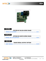
Installation Instructions | Installationsanleitung | Notice d’installation
Istruzioni per l’installazione | Instrucciones de instalación
Minebea Intec Combics, Signum
YDO02C-232, YDO0.SW-232 (Option A1)
YDO02C-485, YDO0.SW-485/422 (Option A3 | A2)
YDO02C-AO, YDO0.SW-AO (Option A9)
YDO02C-ETH, YDO0.SW-ETH (Option B9)
YDO02C-DIO, YDO0.SW-DIO (Option A5)
YDO02C-DP, YDO0.SW-DP (Option B1)
YDO02C-DN (Option B3)
Data Output Port for Combics | Signum UniCOM Interface
Datenausgang für Combics | Signum-Schnittstelle UniCOM
Port de sortie pour interface Combics | Signum UniCOM
Porta in uscita per interfaccia Combics | Signum UniCOM
Puerto de salida para interfaz UniCOM de Combics | Signum
98647-004-24
98647-004-24

2YDO02C
English – page 3
In cases involving questions of interpretation, the German-language version shall prevail.
Deutsch – Seite 32
Im Auslegungsfall ist die deutsche Sprache maßgeblich.
Français – page 61
En cas de questions concernant l’interprétation, la version en langue allemande fera autorité.
Italiano – pagina 90
In caso di interpretazione dubbi a, fa testo la versione in lingua tedesca.
Español – página 119
En caso de interpretación, la versión en lengua alemana será determinante.

3
YDO02C
Contents
Contents...................... 3
Intended Use................... 4
Combics YDO02C-…:
Installing in the Indicator......... 5
Signum: Installing in the Scale ..... 8
Installing the UniCOM Board ....... 9
Installing the Ethernet Board ...... 10
Installing the Profibus Board ...... 11
Configuring the Modules 12
YDO0…-485/422 12
YDO0…-AO 13
YDO0…-ETH 13
YDO0…-DP 14
YDO0…-DIO, Option A5:
Specifications 14
YDO02C-DN, Option B3 15
Pin Assignment Chart 17
Combics UniCOM-IP65K 17
Painted Combics “IP44“/
Signum Models with UniCOM 18
DSUB9 Port (Profibus) 19
DeviceNet 19
Signum:
Stainless Steel / IP65 Models 20
Configuration 21
Combics 1 + 2 21
Combics 3 24
Signum 28
Profibus/Ethernet Interface:
Initialization 31
Ethernet Interface: Features 31
Symbols
The following symbols are used in
these instructions:
§ Indicates steps you must perform
$ Indicates steps you must perform
only under certain conditions
> Describes what happens after you
have performed a particular step
! Indicates a hazard

4YDO02C
Intended Use
Combics UniCOM:
The YDO02C-… data output port is
designed for installation in indicators
and Combics series complete scales as
a UniCOM universal data interface.
– YDO02C-232 (Option A1)
– Connecting an Alibi memory.
– Second display: YRD02Z
– USB adapter cable for connecting
a PC using USB YCC01-USBM2
– Second weighing platform: Weighing
platform with RS-232 data output
– Second weighing platform: IS
platform with optional RS-232
data output
– YDO02C-485 (Options A2 and A3):
Bidirectional data interface, electrically
isolated, optionally utilizable for
RS-422 operation (option A2) or
RS-485 operation (option A3).
Module YDO02C-485 facilitates a
network of up to 32 Combics scales/
indicators using an XBPI bus.
– YDO02C-AO (Option A9):
Analog output port, optionally
utilizable as a current interface
(0/4 – 20 mA, 0 – 24 mA) or as a
voltage interface (0 to10 V).
Module YDO02SW-AO facilitates the
connection of a PLC or external analog
display unit.
– YDO02C-DIO (Option A5):
Digital input/output module for
connecting Combics to external
controllers.
– YDO02C-ETH (Option B9):
Ethernet interface (e.g. for connecting
to a PLC or PC).
– YDO02C-DP (Option B1):
Profibus DP interface (slave) for field
bus applications (e.g. connecting to
a PLC).
Signum UniCOM:
The YDO0.SW-... data output port is
designed for installation in Signum
SIW... complete scales as an optional
standard COM1 interface and/or
UniCOM universal data interface.
– YDP0.SW-232 (Option A1):
– Connecting an Alibi memory.
– Second display: YRD02Z
– USB adapter cable for connecting
a PC using USB YCC01-USBM2
– Second weighing platform: Weighing
platform with RS-232 data output
– Second weighing platform:
IS platform with optional RS-232 data
output
– YDO0.SW-485/422 (Option A2):
Bidirectional RS-422 data interface for
point-to-point-connection using the
SMA/SBI/xBPI protocol
– YDO0.SW-485/422 (Option A3):
Bidirectional RS-485 data interface for
networking with up to 32 scales in an
XBPI bus, additional IS platform with
standard RS-485 data output port.
– YDO0.SW-AO (Option A9):
Analog output port, optionally
utilizable as a current interface
(0/4 – 20 mA, 0 – 24 mA) or as a
voltage interface (0 to10 V).
Module YDO0.SW-AO facilitates the
connection of a PLC or external analog
display unit.
– YDO0.SW-DIO (Option A5):
Digital input/output module for
connecting Signum to external controls.
– YDO0.SW-ETH (Option B9):
Ethernet interface (e. g. for connecting
to a PLC or PC).
– YDO0.SW-DP (Option B1):
Profibus DP interface (slave) for field
bus applications (e.g. connecting to a
PLC).

5
YDO02C
Combics YDO02C-…: Installing in the Indicator
Installation
Installation of the interface module in the Combics indicator (including installation of the cable gland and attachment of the connection
cables to the screw terminal block) is only required if the customer did not order the respective data output port to be fitted in the factory.
Installation option as accessory CAISL1, CAISL2/3, CAIS1/2/3,
of the optional UniCOM interface CAW1P CAW2P, CAW3P CAW1S/2S/3S, CAH1/3
for installation for installation for installation
in IP44 version in IP44 version, in IP69K version
Interface module (RS-232) – • • YDO02C-232
Interface module (RS-485 and RS-485), electrically isolated – • • YDO02C-485
Electrically isolated digital I/Os, 5 outputs and
5 inputs, freely configurable – • • YDO02C-DIO
Analog current output, 0 – 20 mA, 4 – 20 mA, 0 – 10 V, 16 bit 1) – • • YDO02C-AO
DeviceNet interface module 2) • • • YDO02C-DN (B3)
Profibus DP interface module 1) – – • YDO02C-DP
Ethernet interface module – – • YDO02C-ETH
1) Suitable for use in zones 2 + 22, DeviceNet use only with stainless steel cable gland.
2) The shielding of the bus cable is not connected to the device!
Notes:
§ The interface module should only be installed by a trained and authorized Minebea Intec technician.
§ IP69-K protection: Use the appropriate connecting cable with a cable gland designed for the interface module in question
(see “Accessories“).
! Disconnect the equipment from the electricity supply prior to commencing work.
! Improper installation invalidates the applicable warranty.
! Perform all installation work that affects the IP69K protection rating with extreme care.
The cable gland (IP69K protection) for connecting the interface to the indicator is sealed with a protective cap.
Please use extreme caution when performing any work on the cable gland.
§ Remove the front panel: Remove the 10 screws from the front plate.
Installing the UniCOM Board:
§ Unscrew the 2 fixing screws

6YDO02C
§ Screw in the 2 spacing bolts
§ Plug the UniCOM interface module into the digital PCB of the indicator. To do this, insert
the connectors on the interface module into the corresponding ports on the digital PCB.
§ Fasten the interface module with the screws.
Interface modules are equipped with screw terminal blocks.
Attach the connection cables to these terminal blocks.
Attach the DSUB connector (IP44 version)
§ Attach the DSUB connector to the corresponding bulkhead receptacle.
§ Plug the flex cable into the UniCOM digital PCB.
SAT

7
YDO02C
Attach the interface cable
§ Pin Assignments: see “Pin Assignment Chart” section.
§ Attach the connecting cable on the peripheral device to the indicator with the cable
gland.
§ Prepare the interface cable:
– Strip the isolation on the cable end by approx. 10 cm
– Shorten the shield to approx. 1 cm and pull back over the insulation
– Strip approximately 1 cm of the insulation from the connecting cable wires and affix
ferrules to the wire ends.
§ Attach the cable gland:
!Please use extreme caution when performing any work on the equipment that affects this
cable gland. Use a torque wrench. Torque of this cable gland: 5 Nm.
– Remove the protective cap from the bore hole on the indicator
– Push the supplied cable gland through the bore hole and secure from the inside using the
locknut (1).
– Push the cable through the cable gland until the shield (2) makes contact with the clamps
(3). Tighten the compression nut (4) until the sealing insert (5) between compression nut
and cable forms a small bead.
– Check the contact between the shield and the clamps.
§ Attach the connecting cable:
– Securely connect the wires in accordance with the terminal assignment charts.
– For assignment charts see page 16.
§ Close the indicator again. Make sure that the sealing ring between the housing and the
front panel is correctly seated.
§ After completing the installation works, check the IP69K protection. Use a pressure gauge
for this purpose. Contact the Minebea Intec Service Center for further details.
Setting the UniCOM interface for operation
After installing the interface module in the indicator and configuring it, set the UniCOM
interface or “controller” for the intended function with the aid of the operating menu.
See the “UniCOM Settings” section for this purpose. The “Configuration” section of the
operating instructions contains further explanations about this.
4
15
2
3

8YDO02C
Signum: Installing in the Scale
Installation of the interface module in the scale is only required if the customer did not
order the respective data output port to be fitted in the factory.
Notes
§ The interface module should only be installed by a trained and authorized Minebea Intec
technician.
§ IP65 protection:
Use the appropriate connecting cable with a cable gland designed for the interface
module in question (see “Accessories“).
! Disconnect the equipment from the electricity supply prior to commencing work.
! Improper installation invalidates the applicable warranty.
!Perform all installation work that affects the IP65 protection rating with extreme care.
§ Remove the rear wall panel: Remove the 6 screws from the rear wall panel.
§ Carefully remove the rear wall panel. (The RS-232 interface is connected to the digital
PCB by a ribbon cable.)
§ Remove the RS-232 interface (including the accompanying PCB) from the rear wall panel:
Remove the 2 screws from the connector mounting.

9
YDO02C
Installing the UniCOM Board
§ Connect the ribbon cable: Insert the ribbon cable into the applicable slot on the interface
module (YDO0.SW-232, YDO0.SW-485/422, YDO0.SW-AO, YDO0.SW-DIO).
§ Plug the 3 PCB mountings into the interface module.
§ Plug the interface module into the digital PCB of the scale:
Insert the connector of the interface module into the corresponding port on the digital
PCB until the PCB mountings snap into place.
§ Insert the ribbon cable of the interface module into the applicable slot on the connector
board.
$ In the case of interface modules YDO0.SW-485/422 und YDO0.SW-AO: Configure the
interface module (see “Configuring the Modules”, page 12).
§ Fasten the connector belonging to the interface module (including the connector board)
into the applicable opening on the new YAS0.SW-CON rear wall panel (top): Fasten the
2 screws in the connector mounting.
§ Fasten the RS-232 interface (including the connector board) into the applicable opening
on the new rear wall panel (bottom): Fasten the 2 screws in the connector mounting.
§ Seal hole 2 with the cap supplied if no board with a PS/2 port is to be installed.
§ Fasten the rear wall panel to the scale: Fasten the 6 screws.
$ Where applicable, attach labels to the rear wall panel to identify the interfaces.
Setting the UniCOM interface for operation
After installing the interface module in the indicator and configuring it, set the UniCOM
interface for the intended function with the aid of the operating menu. See the “Settings”
section for this purpose. The “Configuration” section of the Signum operating instructions
contains further explanations about this.

10 YDO02C
Installing the Ethernet Board
§ Fasten the RS-232 interface (including the connector board) into the applicable opening
on the new rear wall panel (bottom): Fasten the 2 screws in the connector mounting.
§ Fasten the interface module (YDO0.SW-ETH - Ethernet port including the connector
board) into the applicable opening on the rear wall panel supplied (top): Fasten the
2 screws in the connector mounting.
§ Connect the ribbon cable: Insert the ribbon cable for Ethernet connection into the
applicable slot on the digital board (on the left in the illustration).
$ Insert the ribbon cable for the RS-232 interface into the applicable slot on the digital
board (on the right in the illustration).
§ Insert the ribbon cable for the Ethernet connection into the applicable slot on the
interface module (YDO0.SW-ETH).
$ Insert the ribbon cable for the RS-232 interface into the applicable slot on the connector
board (on the left in the illustration).
§ Fasten the rear wall panel to the scale: Fasten the 6 screws.
Configuring the Ethernet interface for operation
After installing the interface module in the indicator and configuring it, configure the
Ethernet interface for its intended function with the aid of the operating menu. See the
“Settings” section for this purpose. The “Configuration” section of the Signum operating
instructions contains further explanations about this.

11
YDO02C
Installing the Profibus Board
§ Fasten the RS-232 interface (including the connector board) into the applicable opening
on the new rear wall panel (bottom): Fasten the 2 screws in the connector mounting.
§ Connect the ribbon cable: Insert the ribbon cable for Profibus connection into the
applicable slot on the digital board (on the left in the illustration).
$ Where applicable, insert the ribbon cable for the RS-232 interface into the applicable slot
on the digital board (on the right in the illustration).
§ Attach the connecting cable:
– Securely attach the 4 conductors in accordance with their color coding.
– Plug the connector on the cable into the socket on the right.
§ Insert the ribbon cable for the Profibus connection into the applicable slot on the
interface module (YDO0.SW-DP).
$ Where applicable, insert the ribbon cable for the RS-232 interface into the applicable slot
on the connector board (on the left in the illustration).
§ Fasten the rear wall panel to the scale: Fasten the 6 screws.
Configuring the Profibus interface for operation
After installing the interface module in the scale and configuring it, configure the
Profibus interface for its intended function with the aid of the operating menu.
See the “Settings” section for this purpose. The “Configuration” section of the Signum
operating instructions contains further explanations about this.

12 YDO02C
YDO0…-485/422 (Options A2 and A3)
Equipment Supplied
– Interface module
– 3 PCB mountings
– Installation instructions (this manual)
Features
Interface module YDO0…-485/422 (serial RS-485/RS-422 interface, electrically isolated1)
can either be operated in RS-485 or RS-422 mode.
Configuration for intended use is implemented using eight switches.
Configuring for intended use as an RS-485 or RS-422 interface, depending on the
area of application (network or point-to-point connection), requires the activation or
deactivation of the terminating resistors (120 O) and the bias resistors located on the
board.
The arrangement of the switches is displayed in the drawing on the left.
When switch 1 – 4 is closed, the interface is configured for RS-422 operation.
The following functions are available when the relevant switch is closed (setting: “ON“):
Function (ON = closed) Switch
Terminating resistor, transmitting side 120 O 1 – 1
BIAS resistor, transmitting side (TxD+, pull-up) 680 O 1 – 2
BIAS resistor, transmitting side (TxD–, pull-down) 680 O 1 – 3
ON: RS-422 operation (A2) | open: RS-485 operation (A3) 1 – 4
Terminating resistor, receiving side 120 O 2 – 1
BIAS resistor, receiving side (RxD+, pull-up) 680 O 2 – 2
BIAS resistor, receiving side (RxD–, pull-down) 680 O 2 – 3
No function 2 – 4
! Note on setting the switches
Switches must be set pairwise as follows:
– Switches 1–2 and 1–3: both ON or both OFF
– Switches 2–2 and 2–3: both ON or both OFF
Operation as an RS-485 interface (Option A3):
§ Switch 1–4 must be open in order to switch to RS-485 operation (factory setting).
$ Where applicable, deactivate bias resistors for RS-485 operation. Open switches for this
purpose (factory setting).
There must only be one instance of bias resistors per transmission path (network or
point-to-point connection). Otherwise there is a risk of transmission errors. Where
applicable, refer to the specifications or circuit documentation for the remote station or
network nodes in question. Bias resistors must always be activated or deactivated in pairs.
§ The terminating resistor (transmitting side, switch 1 – 1) must be activated if the device is
located at either end of an RS-485 bus system, or where it is connected to another device
in a point-to-point link. There must also be a terminating resistor of 120 O in place at
the remote station. Where applicable, activate terminating resistor (120 O) for RS-485
operation:
Close switches 1–1 („ON” setting)
Operation as an RS-422 interface (Option A2):
§ Close switch 1–4 in order to switch to RS-422 operation.
$ Where applicable, deactivate bias resistors for RS-422 operation. Set the switches to the
open position for this purpose.
§ Activate the receiving side terminating resistor (switch 2–1), if no external terminating
resistor is in place. Always deactivate TX terminating resistors (switch 1 – 1).
1) The shielding of the connecting cable is connected to the indicator housing at one end.
The indicator is connected to the protective grounding conductor.
Configuring the Modules

13
YDO02C
YDO0…-AO (Option A9)
Equipment Supplied
– Interface module
– PCB mountings
– Installation instructions (this manual)
Characteristics
Interface module YDO0…-AO is an analog output port. It can be operated as a current
interface (0/4 – 20 mA, 0 – 24 mA) or as a voltage interface (0 to 10 V). The voltage
supply is internally electrically isolated1.
The interface module can be configured for any one of the following four modes of
operation:
– Voltage interface, 0 to 10 V
– Current interface, 0 to 20 mA
– Current interface, 4 to 20 mA
– Current interface, 0 to 24 mA
Configuration for intended use is implemented by opening and closing switches.
The arrangement of the switches is displayed in the drawing on the left.
Setting of the applicable operating mode is implemented by setting switches 1 and 2
(switches 3 and 4 have no function):
Operating status Switch
Voltage interface, 0 to 10 V SW 1–1: “ON”, SW 1–2: OFF
Current interface, 0 to 20 mA SW 1–1: OFF, SW 1–2: “ON”
Current interface, 4 to 20 mA SW 1–1: OFF, SW 1–2: OFF (factory setting)
Current interface, 0 to 24 mA SW 1–1: “ON”,
SW 1–2: “ON”
1) The shielding of the connecting cable is connected to the scale housing at one end.
The scale is connected to the protective grounding conductor.
Notes
– Max. load: 390 ohms
– The shielding of the current interface connecting cable is connected to the indicator
housing at one end.
– The scale is connected to the protective grounding conductor.
– If the scale is powered using an internal or external rechargeable battery pack, it is not
possible to operate the current interface.
§ Interface module YDO0…-AO is attached directly onto the digital board of the indicators.
For more information, please refer to the section entitled “Installing in the Indicator”.
YDO0…-ETH (Option B9)
Equipment Supplied
– Interface module YDO0…-ETH
– Installation instructions (this manual)
– „Field bus” software interface description for Modbus/TCP operation
Assembly
Connect interface module YDO0…-ETH (Ethernet interface) directly to the digital board
of the scale without configuration. For more information, please refer to the section
entitled “Installing in the Indicator”.
Note:
! Only use cables and plugs that conform to the Ethernet specification (CAT5 or higher).

14 YDO02C
YDO0…-DIO, Option A5: Specifications
Digital inputs
– Quantity: 5
– Low level: -3 V to +5 V
– High level: +11 V to +30 V
– Maximum current
consumption: 2.6 mA at 15 V
– Switching of inputs by applying the correct voltage.
Digital outputs
– Quantity: 5
– Maximum current conduction per channel: 100 mA
– Voltage range: 0-30 V DC
– Each output is created by an optoelectronic coupler.
OUTx_high
30V
0.2A
Inputx_high
LV1
LV1
OUTx_low
1
23
4
1
23
4
LV2
LV2
Inputx_low
OUTx_high
30V
0.2A
Inputx_high
LV1
LV1
OUTx_low
1
23
4
1
2
3
4
LV2
LV2
Inputx_low
YDO0…-DP (Option B1)
Equipment Supplied
– Interface module
– Installation instructions (this manual)
– “Field bus” software interface description
– GSD file: see Minebea Intec website “Minebea Intec Mechatronics Software download:
Select product: Fieldbus files“
Assembly
Connect interface module YDO0…-DP (Profibus interface) directly to the digital board
of the scale, without configuration. For more information, please refer to the section
entitled “Installing in the Indicator”. Any terminating resistors that may be necessary for
the bus system must be installed outside the indicator. The voltage required for this is
supplied internally by the indicator. A bus connection is required at both ends of the bus
system. This is achieved either by
– Termination within the connecting plugs (at baud rates > 1.5 Mbit/s with additional
inductances)
or by
– Internal bus terminations.
Use switches 1 through 4 to set the particular resistor:
Operating status Switch
390 ohms bias resistor against GND SW 1–1: ON
220 ohms terminating resistor SW 1-2: ON
220 ohms terminating resistor SW 1-3: ON
390 ohms bias resistor against 5 V SW 1-4: ON
Note: SW 1–2 and SW 1–3 – or all switches – must be activated simultaneously.
Use the 5V supply voltage only for activating external bias resistors in accordance with
the Profibus-DP specification.
Notes:
! Only use cables and plugs that conform to the Profibus specification.
! Connect the shielding of the connecting cable to the housing.
Example: Basic wiring diagram
GND
A
B
V
P
390 O
220 O
390 O
Terminating resistors
for Profibus

15
YDO02C
YDO02C-DN (Option B3)
Equipment Supplied
– Interface module
– Installation instructions (this manual)
- Cable gland
- Shielding
- Self-adhesive aluminum foil
- ferrite core
– „Fieldbus“ software interface description
– EDS file: see Minebea Intec website „minebea-intec Mechatronic Software download:
Select product: Fieldbus files“
Assembly
Connect interface module YDO0…-xxx (DeviceNet interface) directly to the digital board
of the scale, without configuration. For more information, please refer to the chapter
entitled „Installing in the Indicator“.
Operation
- MAC ID is selectable in a range from 1 to 62
- Selectable baud rates of 125k, 250k and 500k bps
- Quick connect function selectable
- Functions as a slave
- Interface electrically isolated
Note:
! !Only use cables and plugs that conform to the Profibus specification

16 YDO02C
DeviceNet-Installation YDO02C-DN (B3)
Combics 1 Combics 2/3
DeviceNet - Installation:
- Open the housing
- Mount the DeviceNet Board (* 1) to the motherboard (* 3)
with bolts and screws
- Assemble the cable gland
- Prepare the DeviceNet - Cable (2 *)
- Pull the cable through the ferrite core
- Connect the DeviceNet - Cable at the terminal
- Fasten the cable to the cable gland
- The cable shield is not connected to the case
- Remove the screw near the strain gauge terminal and fasten the
metal sheet, which covers the red capacitors, with the same screw 1)
- Additionally a conductive fastening to the Board Level Shield is
realized with a piece of self-adhesive aluminum tape 1)
1) Combics 1
3*) Mainboard
1*) DeviceNet
Board
(UniCom)
5*) Analog to Digital Converter
(ADC)
with Board Level Shield
2*) DeviceNet
Cable
4*) ADC
Capacitors
DeviceNet Installation:
Open the housing.
Mount the DeviceNet Board (*1) to the
Mainboard (*3) with distance bolts and screws.
Mount the cable gland.
Prepare the DeviceNet – Cable(2*).
Connect the DeviceNet – Cable at the terminal.
Fasten the cable with the cable gland.
Remove the screw near the strain gauge
terminal and fasten the metal sheet, which
covers the red capacitors, with the same screw.
Additionally a conductive fastening to the Board
Level Shield is realized with a piece of
selfadhesive aluminum tape.

17
YDO02C
Pin Assignment Chart
Combics UniCOM-IP69K
– Pin assignment of the two 10 pin
screw terminal blocks on the interface
module:
RS-232 mode: YDO02C-232
(Option A1):
Pin 1: Clear to send (CTS)
Pin 2: Data terminal ready (DTR)
Pin 3: Data input (R+D)
Pin 4: Data output (T+D)
Pin 5: Ground (GND)
Pin 6: Universal In
pin 7: Control output: “lower“
Pin 8: Control output: “same“
Pin 9: Control output: “higher“
Pin 10: Control output: “set“
Pin 11: +12 V operating voltage for
Minebea Intec printer
Pin 12: Reset_Out
(Periphery restart)
Pin 13: Ground (GND)
Pin 14: Ground (GND)
Pin 15: +5 V output
Pin 16: +5 V switched
(e.g. for barcode reader)
Pin 17: Ground (GND)
Pin 18: Ground (GND)
Pin 19: Not in use
Pin 20: Ext. transmitting
voltage output
+15 ... 25 V
Profibus: YDOO02C-DP (Option B1)
Pinch connector
Connection Function
1 R+D/T+D-P, Line B, red
2 R+D/T+D-N, Line A, green
3 R+D/T+D-N, Line A, green
4 R+D/T+D-P, Line B, red
5 GND
6 +5 V (for ext. termination)
4 3 2 1
5/6
Digital input/output interface:
YDO02C-IO (Option A5):
Pin 1: External output port 5: low
Pin 2: External output port 5: high
Pin 3: External output port 4: low
Pin 4: External output port 4: high
Pin 5: External output port 3: low
Pin 6: External output port 3: high
Pin 7: External output port 2: low
Pin 8: External output port 2: high
Pin 9: External output port 1: low
Pin 10: External output port 1: high
Pin 11: Input port 5: low
Pin 12: Input port 5: high
Pin 13: Input port 4: low
Pin 14: Input port 4: high
Pin 15: Input port 3: low
Pin 16: Input port 3: high
Pin 17: Input port 2: low
Pin 18: Input port 2: high
Pin 19: Input port 1: low
Pin 20: Input port 1: high
– Pin assignment of the two screw
terminal blocks on the interface
module:
RS-485 mode: YDO02C-485
(Option A2):
Pin 1: Data (T+D-R+D+)
Pin 2: Data - (T+D-R+D-)
Pin 3: Not in use
Pin 4: Not in use
Pin 5: Ground signal, electrically
isolated (GND_GALV)
Pin 6: Ground signal, electrically
isolated (GND_GALV)
Pin 11: Ext. transmitting voltage input
+15 ... 25 V *
Pin 12: Ext. transmitting voltage input
+15 ... 25 V *
Pin 13: Ground (GND) *
Pin 14: Ground (GND) *
1
234566
RS-422 mode: YDO02C-485:
(Option A3):
Pin 1: Data output + (T+D+)
Pin 2: Data output - (T+D-)
Pin 3: Data input + (R+D+)
Pin 4: Data input - (R+D-)
Pin 5: Ground signal, electrically
isolated (GND_GALV)
Pin 6: Ground signal, electrically
isolated (GND_GALV)
Pin 11: Ext. transmitting voltage input
+15 ... 25 V *
Pin 12: Ext. transmitting voltage input
+15 ... 25 V *
Pin 13: Ground (GND) *
Pin 14: Ground (GND) *
* = not electrically isolated
Current / voltage interface
YDO02C-AO, Option A9:
6 pin screw terminal block on the
interface module
Pin 1: I_out (+)
for current interface
(0/4 to 20/24 mA)
Pin 2: I_in (–)
for current interface
(0/4 to 20/24 mA)
Pin 3: V_out (+)
for voltage interface,
0 to 10 V
Pin 4: V_in (–)
for voltage interface,
0 to 10 V
Pin 5: GND, electrically isolated
(electrically isolated ground)
Pin 6: GND, electrically isolated
(electrically isolated ground)
Pin assignment of the Ethernet
interface (RJ45)
YDO02C-ETH: Option B9:
Pin 1: TxD+
Pin 2: TxD–
Pin 3: RxD+
Pin 4: Not in use
Pin 5: Not in use
Pin 6: RxD–
Pin 7: Not in use
Pin 8: Not in use
Chassis: GND
1
234566
1
234566

18 YDO02C
Painted Combics “IP44”
and Signum models with
UniCOM interface
25-pin D-Submini (DB25S) with screw
connection
Front view
Required interface connector
(recommended):
25-pin D-Submini (DB25) with shielded
cable clamp assembly and shield plate
(Amp type 826 985-1C) and fastening
screws (Amp type 164868-1)
RS-232 mode:
YDO0…-232 (Option A1):
Pin 1: GND
Pin 2: TxD
Pin 3: RxD
Pin 4: GND
Pin 5: CTS
Pin 6: Not in use
Pin 7: GND
Pin 8: GND
Pin 9: Not in use
Pin 10: Not in use
Pin 11: +12 V operating voltage for
Minebea Intec printer
Pin 12: RESET_OUT
(Periphery restart)
Pin 13: 5 V switched
(e.g. for barcode reader)
Pin 14: GND
Pin 15: Universal In
Pin 16: Control output: “lower“
Pin 17: Control output: “same“
Pin 18: Control output: “higher“
Pin 19: Control output: “set“
Pin 20: DTR
Pin 21: GND
Pin 22: Not in use
Pin 23: Not in use
Pin 24: Ext. transmitting
voltage output
+15 ... +25 V
Pin 25: 5 V_Output
RS-422 mode: YDO0…-422
(Option A2):
Pin 1: GND, electrically isolated
Pin 2: TxD+, electrically isolated
Pin 3: RxD+, electrically isolated
Pin 4: Not in use
Pin 5: RxD-, electrically isolated
Pin 6: Not in use
Pin 7: GND, electrically isolated
Pin 8: GND, electrically isolated
Pin 9: Not in use
Pin 10: Not in use
Pin 11: Not in use
Pin 12: Not in use
Pin 13: Not in use
Pin 14: Not in use
Pin 15: Not in use
Pin 16: Not in use
Pin 17: Not in use
Pin 18: Not in use
Pin 19: Not in use
Pin 20: TxD-, electrically isolated
Pin 21: GND
Pin 22: Not in use
Pin 23: Not in use
Pin 24: Ext. transmitting voltage input
+15 ... +25V, not electrically
isolated
Pin 25: Not in use
RS-485 mode: YDO0…-485
(Option A3):
Pin 1: GND, electrically isolated
Pin 2: TxD/RxD+
Pin 3: RxD+, electrically isolated
Pin 4: Not in use
Pin 5: RxD-, electrically isolated
Pin 6: Not in use
Pin 7: GND, electrically isolated
Pin 8: GND, electrically isolated
Pin 9: Not in use
Pin 10: Not in use
Pin 11: Not in use
Pin 12: Not in use
Pin 13: Not in use
Pin 14: Not in use
Pin 15: Not in use
Pin 16: Not in use
Pin 17: Not in use
Pin 18: Not in use
Pin 19: Not in use
Pin 20: TxD/RxD–
Pin 21: GND
Pin 22: Not in use
Pin 23: Not in use
Pin 24: Ext. transmitting voltage input
+15 ... +25V, not electrically
isolated
Pin 25: Not in use
Current/voltage interface:
YDO0…-AO (Option A4)
Pin 1: GND, electrically isolated
Pin 2: Not in use
Pin 3: Not in use
Pin 4: Not in use
Pin 5: Not in use
Pin 6: V_out (+), electrically isolated,
for voltage interface,
0 to 10 V
Pin 7: V_in (-), electrically isolated,
for voltage interface,
0 to 10 V
Pin 8: Not in use
Pin 9: I_out (+), electrically isolated,
for current interface,
(0/4 to 20/24 mA)
Pin 10: I_in (–), electrically isolated,
for current interface,
(0/4 to 20/24 mA)
Pin 11: Not in use
Pin 12: Not in use
Pin 13: Not in use
Pin 14: GND, electrically isolated
Pin 15: Not in use
Pin 16: Not in use
Pin 17: Not in use
Pin 18: Not in use
Pin 19: Not in use
Pin 20: Not in use
Pin 21: Not in use
Pin 22: Not in use
Pin 23: Not in use
Pin 24: Not in use
Pin 25: Not in use
Digital input/output module
YDO0…-DIO: (Option A5)
Pin 1: OUT1_HIGH
Pin 2: OUT2_HIGH
Pin 3: OUT3_HIGH
Pin 4: OUT4_HIGH
Pin 5: OUT5_HIGH
Pin 6:
Pin 7: IN1_HIGH
Pin 8: IN2_HIGH
Pin 9: IN3_HIGH
Pin 10: IN4_HIGH
Pin 11: IN5_HIGH
Pin 12:
Pin 13:
Pin 14: OUT1_LOW
Pin 15: OUT2_LOW
Pin 16: OUT3_LOW
Pin 17: OUT4_LOW
Pin 18: OUT5_LOW
Pin 19:
Pin 20: IN1_LOW
Pin 21: IN2_LOW
Pin 22: IN3_LOW
Pin 23: IN4_LOW
Pin 24: IN5_LOW
Pin 25:

19
YDO02C
Pin assignment of the Ethernet interface (RJ45)
YDO0…-ETH (Option B9):
Pin 1: TxD+
Pin 2: TxD-
Pin 3: RxD+
Pin 4: Not in use
Pin 5: Not in use
Pin 6: RxD-
Pin 7: Not in use
Pin 8: Not in use
Chassis: GND
Pin assignment of the Profibus interface
YDO0…-DP, IP44 (Option B1):
Pin 1: Not in use
Pin 2: Not in use
Pin 3: RxD / TxD-P
Pin 4: RTS_PDP
Pin 5: GND_BUS
Pin 6: +5V_BUS
Pin 7: Not in use
Pin 8: RxD / TxD-N
Pin 9: Not in use
Housing: grounded
Pin assignment of the PS/2 port
Pin 1: Keyboard Data (data link)
Pin 2: Not in use
Pin 3: GND (ground / chassis ground)
Pin 4: 5V switched
Pin 5: Keyboard Clock (cycle)
Pin 6: Not in use
Pin assignment of the DeviceNet interface
Pin 1: V-
Pin 2: CAN_L
Pin 3: SHIELD
Pin 4: CAN_H
Pin 5: V+
6
51
9
3
1
4
2
65

20 YDO02C
Signum: Stainless Steel / IP65 Models
UniCOM RS-232 (Option A1), RS-422 (Option A2), RS-485 (Option A3),
4–20 mA (Option A9)
UniCOM
Pin RS-232 RS-485 RS-422 4–20 mA
A Control output: “higher“ – – –
B TxD RxD-TxD-N TxD-N I_OUT(+)
C RxD RxD-TXD-P TxD-P I_IN(-)
D DTR – RxD-P V_OUT(+)
S GND Signal GND Signal_GND –
F 5V – – –
G Control output: “lower“ Line ( 11-30V ) – –
H CTS – RxD-N V_IN(-)
Y Control output: “same“ Line GND Line GND –
K UNIVERSAL_IN Line GND Line GND –
L Control output: “Set“ – – –
M LOAD_PRINTER Line ( 11-30 V ) Line ( 11-30V ) –
Digital I/O 5/5 optically isolated (Option A5)
Pin UniCOM / Digital I/O
Connector A (top) Connector B (bottom)
A OUT1_HIGH OUT5_HIGH
B OUT1_LOW OUT5_LOW
C OUT2_HIGH –
D OUT2_LOW –
S OUT3_HIGH –
F OUT3_LOW –
G OUT4_HIGH IN3_HIGH
H OUT4_LOW IN3_LOW
Y IN1_HIGH IN4_HIGH
K IN1_LOW IN4_LOW
L IN2_HIGH IN5_HIGH
M IN2_LOW IN5_LOW
Profibus (Option B1)
The Profibus interface has two B-coded M12 circular plug-in connectors
Pin UniCOM / Digital I/O
Input Output
1 – 5 V
2 RxD / TxD-N RxD / TxD-N
3 – GND
4 RxD / TxD-P RxD / TxD-P
5 – –
Ethernet
1. TXD+
2. TXD-
3. RXD+
4. Not in use
5. Not in use
6. RxD-
7. Not in use
8. Not in use
Chassis: GND
View on device
A
B
View on device
Input
Output
/