Page is loading ...

Service Manual
Multi-Pipe VRF Connecting Box Module
VOB5-2C
VOB5-3C
VOB5-5C
©2015 Innovair Corporation. All Rights Reserved. www.innovair.com/support

◆
Nameplate (model, cooling capacity, product code, ex-factory date).
◆
Malfunction status (detail description of conditions before and after malfunction occurs).
7) It is a normal phenomenon that the fan of indoor unit will still run for 20~70 seconds after the
indoor unit receives the “stop” signal so as to make full use of the waste heat.
8) When the work mode of the indoors is conflict with the modes of outdoor units, it will be
indicated on the display of the wired controller in five seconds and then the indoor unit will
stop. In this case, please harmonize their work modes: the cooling mode is compatible with the
dry mode.
9) If the supply power fails when the unit is running, then the indoor unit will send the “start”
signal to the outdoor unit three minutes later after the power recovery.
10) The power cable and transmission line must not be twisted together, but instead of separated
with an interval of at least 2cm; otherwise it may be result in communication problem.
11) This appliance is not intended for use by persons (including children) with reduced physical,
sensory or mental capabilities, or lack of experience and knowledge, unless they have been
given supervision or instruction concerning use of the appliance by a person responsible for
their safety. Children should be supervised to ensure that they do not play with the appliance.
12) All graphics and information in this manual are only for reference. Manufacturer reserves the
right for changes in terms of sales or production at any time and without prior notice.
This product must not be disposed together with the domestic waste. This product has
to be disposed at an authorized place for recycling of electrical and electronic appliances.
Thank you for purchasing Innovair’s air conditioners. Before using, please read
this manual carefully and keep it properly for further reference.
©2015 Innovair Corporation. All Rights Reserved.
www.innovair.com

Contents
1 Safety Precautions ....................................................................................................................... 1
2 Product Introduction ................................................................................................................... 3
2.1 Names of Main Parts ......................................................................................................... 3
2.2 Combinations for Outdoor and Indoor Units .................................................................... 4
2.3 Parts and Components of Unit .......................................................................................... 4
2.4 Working Temperature Range ............................................................................................ 4
3 Selection of Installation Location and Precautions ..................................................................... 5
3.1 Selection of Installation Location ..................................................................................... 5
3.2 Outline Dimension and Servicing Space of VOB5-2C ..................................................... 8
3.3 Outline Dimension and Servicing Space of VOB5-3C ..................................................... 9
3.4 Outline Dimension and Servicing Space of VOB5-5C ................................................... 10
4 Installation Instruction .............................................................................................................. 11
5 Installation of Refrigerant Pipes ............................................................................................... 12
5.1 Allowable Length and Drop Height of Connecting Pipe ................................................ 12
5.2 Installation of Piping Adapter (VOB5-5C) ..................................................................... 12
5.3 Installation of Piping Adapter (VOB5-2C and VOB5-3C) ............................................. 13
5.4 Precaution for Connection .............................................................................................. 15
6 Electrical Wiring Work ........................................................................................................................ 17
6.1 Wiring Connection .......................................................................................................... 17
6.2 Requirements of Power Circuit and Cable ...................................................................... 17
6.3 Ground Requirements ..................................................................................................... 18
6.4 Precautions on the Electrical Wiring Work ............................................................................18
6.5 Precaution of Laying Wires ............................................................................................ 19
6.6 Procedures for Electrical Wiring Work ...................................................................................19
6.7 Instructions for DIP Switch ............................................................................................. 21
7 Design of Drainage Pipeline ..................................................................................................... 22
7.1 Installation of Drain Hose ............................................................................................... 22
7.2 Design of Drainage Pipeline ........................................................................................... 22
8 Test Operation ........................................................................................................................... 22
9 Troubleshooting ........................................................................................................................ 23
©2015 Innovair Corporation. All Rights Reserved.
www.innovair.com

VOB Module
1
1
Safety Precautions
This is the safety alert symbol. It is used to alert you to potential personal injury
hazards. Obey all safety messages that follow this symbol to avoid possible injury or
death.
WARNING
This mark indicates procedures which, if improperly performed, might lead to the
death or serious injury of the user.
CAUTION
This mark indicates procedures which, if improperly performed, might possibly result
in personal harm to the user, or damage to property.
NOTICE
NOTICE is used to address practices not related to personal injury.
WARNING
1) Instructions for installation and use of this product are provided by the manufacturer.
2) Installation must be performed in accordance with the requirements of NEC and CEC by appointed
personnel only.
3) The installation should be left to the appointed service center and according to the instructions given in the
manual. Improper installation may cause fall down, water leakage, electric shock or fire etc.
4) For operating the air conditioner pleasantly, please install it as outlined in this installation manual.
5) The power supply must adopt the special circuit with air switch protection and assure it has enough capacity
6) Connect the indoor unit, VOB Module and outdoor unit with the room air conditioner piping and cord
available from our standard parts. This installation manual describes the correct connections using the
installation set available from our standard parts.
7) Before installation, check the parameter of power cord and make sure that it complies with the power
supply requirement on the nameplate. Make sure the power supply is safe.
8) This air conditioner must be properly grounded through the receptacle to avoid electric shock. The ground
wire shouldn’t be connected with gas pipe, water pipe, lightning arrester or telephone line.
9) If refrigerant leaks while work is being carried out, ventilate the area. If the refrigerant comes in contact
with a flame, it produces toxic gas.
10) Do not power on until all installation work is complete.
11) During installation, make sure that the refrigerant pipe is attached firmly before you start up the compressor.
Do not operate the compressor under the condition of refrigerant piping not attached properly with valve
open. This may cause abnormal pressure in the refrigeration cycle that leads to breakage and even injury.
12) When installing and relocating the air conditioner, do not mix gases except the specified refrigerant
(R410A) to enter the refrigerant cycle. If air or other gas enters the refrigerant cycle, the pressure inside the
cycle will rise to an abnormally high value and cause breakage, injury, etc.
13) This appliance is not intended for use by persons (including children) with reduced physical, sensory or
mental capabilities, or lack of experience and knowledge, unless they have been given supervision or
instruction concerning use of the appliance by a person responsible for their safety. Children should be
supervised to ensure that they do not play with the appliance.
14) Never cut off or damage power cables and transmission wires. If the power cable or transmission line were
damaged, it must be replaced by the manufacturer, its service agent or similarly qualified persons in order to
avoid a hazard.
15) After the power cord is connected, please install the cover of electric box to avoid danger.
©2015 Innovair Corporation. All Rights Reserved.
www.innovair.com

BU Mo
dule
16) When installing or relocating the unit, please contact the appointed service center for the repair or
relocation. Meanwhile the specialized parts and accessories must be used. Otherwise, it may result in water
leakage, electric shock or fire hazard.
17) Diameter of power cord must be large enough. Damaged power cord or connecting wire must be replaced
by specialized electric cable.
18) The power wire and transmission line must be more than one meter away from televisions or radios which
can emit electromagnetic waves to prevent image interference or noise. Otherwise, the unit maybe not work
19) Nitrogen must be charged according to technical requirements.
20) For units with wired controllers, do not connect power supply until the wired controller is well installed.
Otherwise, the wired controller cannot be used.
21) When installation is finished, please check and make sure the drain pipe, pipeline and electric wire are all
well connected so as to avoid water leakage, refrigerant leakage, electric shock and fire hazard.
22) Never extend fingers or objects into air outlet or return air grille.
23) Please keep the room well-ventilated and it could avoid oxygen deficit.
24) Never start or stop the air conditioner by inserting or removing the power cord.
25) Before startup of the compressor, please turn on the main power switch of the unit for more than 8 hours
and it makes sure that the heater belt of the compressor has been energized for at least eight hours! Once the
compressor is started, it must be guaranteed that it works continuously for at least 30 minutes, otherwise it
would be damaged!
26) Never operate the unit with wet hands. Otherwise, it may cause electric shock.
27) Before cleaning and repairing, it is necessary to stop working and turn off the power supply. Otherwise, it
may cause electric shock or damage.
28) Do not spray water on the air conditioner or it will cause malfunction or electric shock.
29) The air conditioner is not support to install in the circumstances as the following that where there is full of
mist of oil, damp or corrosive gas, flammable gases, the acidic or alkaline vapor and the ocean.
30) Volatile liquid like thinner or gasoline will damage the appearance of air conditioner. (Please use soft dry
cloth and wet cloth with mild detergent to clean unit’s appearance.)
31) Never standing or place objects on outdoor unit. Person or objects falling from the unit may cause injury.
32) If abnormal condition occurs (e.g. unpleasant smell), please turn off the unit at once and disconnect power
supply. Then contact appointed service center. If the air conditioner continues to operate despite of
abnormal condition, it may be damaged and cause electric shock or fire hazard.
33) The drain pipe should be installed as instructed in the manual to guarantee the proper drainage; meanwhile
it should be insulated to prevent condensing; otherwise the improper installation would cause water leakage
and then wet the household wares in the room.
34) Don't attempt to repair the air conditioner by yourself. The improper repair will lead to electric shock or
fire, please contact the appointed service center and ask professional technicians to repair it.
35) Please take notice of the installation foundation of the unit after long use, if it is damaged, it may lead to the
fall of the unit and cause the injury.
36) Be sure to shut off the power supply when you do not use the air conditioner for a long time. Otherwise, the
dusts may accumulate in it, which may cause overheating or fire hazards.
37) Innovair Corporation is not responsible for any personal injury or property loss caused by improper
installation, improper debugging, unnecessary repair or not following the instructions of this
manual.
©2015 Innovair Corporation. All Rights Reserved.
www.innovair.com

VOB Module
3
2
Product Introduction
The VOB module of Innovair’s Multi-Pipe VRF Series is the latest branch device, which adopts
the
intelligent control technology. Respond to the changes in load of the indoor units, it can
coordinate
the flow rate of the refrigerant well. Otherwise, it is very compact and has a flexible
choice about the
installation location, such as the ceiling of parlor, corridor, balcony, storeroom and
etc.
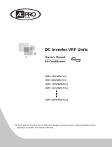
2.1 Names of Main Parts
VOB5-2C VOB5-3C
VOB5-5C
NO.
①
②
③
④
Name
Gas piping of indoor unit
side
Liquid piping of indoor
unit side
Hanger metal
Electrical
equipment plate
NO.
⑤
⑥
⑦
⑧
Name
Liquid piping of outdoor
unit side
Gas piping of outdoor unit
side
Drain hole
Printed circuit
board
Fig. 1
©2015 Innovair Corporation. All Rights Reserved.
www.innovair.com

BU Mo
dule
2.2 Combinations for Outdoor and Indoor Units
Table 1
Sorts
VOB5-2C
VOB5-3C
VOB5-5C
No. of connectable
indoor units
Min
1
1
1
Max
2
3
5
2.3 Parts and Components of Unit
For the Super Free Match Series, one outdoor unit is able to drive up to three VOB Modules and
nine indoor units which include cassette type, duct type, wall-mounted type, floor ceiling type and
console type. The outdoor unit will run as long as any one indoor unit receives the running command,
and all indoor units stop once the outdoor unit is turned off.
Power supply wire for outdoor
unit and VOB Module(3 wires)
Connection pipe
Transmission line(2 wires)
Power supply wire for
indoor unit(4 wires)
Ground
Power
BU 3
Indoor unit
Duct type
Wall mounted
type
Floor ceiling
type
Console type
Wall mounted
type
Outdoor unit
Ground
The 2nd
branch
The 1st
branch
Power
(60Hz, 208/230V)
(60Hz, 208/230V)
BU 2
Ground
Power
(60Hz, 208/230V)
BU 1
Ground
Power
(60Hz, 208/230V)
Fig. 2
Cassette type
Cassette type
Duct type
Wall mounted
type
2.4 Working Temperature Range
Table 2
Sorts
Outside temperature: DB(℃/℉)
Maximum
50℃(122℉)
Minimum
-15℃(5℉)
©2015 Innovair Corporation. All Rights Reserved.
www.innovair.com

VOB Module
5
3
Selection of Installation Location and Precautions
WARNING
1) The installation of the air conditioner must be in accordance with the national and local laws and
regulations.
2) The quality of the installation will affect the capability of air conditioner directly. The installation
should be left to the appointed service center. Please contact your dealer after purchasing this machine.
Professional installation workers will provide installation and test services according to the installation
manual.
3) The air conditioner should not install in this place where the small animals exist, because they may
cause malfunctions, smoke or fire. Please keep the area around the unit clean.
3.1 Selection of Installation Location
WARNING
1) The VOB Module must be installed on a firm and solid support which can withstand the weight of
the
module and the mounting surface must be horizontal plane. The VOB Module can be chosen to
install in
the ceiling, such as the ceiling of parlor, corridor, balcony, storeroom and etc.
2) The location must be out of children’s reach, please keep the unit away from children.
3) The VOB Module is for indoor use. If installing in the outdoors, the location must be away from wind
and
rain. Otherwise, it maybe causes water leakage, electric shocks or fire etc.
4) There is enough space for the installation and maintenance.
5) Avoid direct sunlight or other heat sources exist.
6) Do not install in location that is hot or humid for long periods of time.
7) Avoid the VOB Module installed in the bedroom and study, where these places need to be quiet.
8) VOB Module cannot be installed in the place of inflammable and explosive materials and severe dust,
smoke and the other air pollution, such as the kitchen.
9) There is enough space to install drainage pipe, so that the condensed water can be discharged.
10) Installation at the following places might lead to the air conditioner malfunction, such as where is full of
machine oil, saline-sodic soil near the sea, sulphide fog, high frequency facilities or special conditions.
If it is unavoidable, please contact the appointed service center.
NOTICE
1) Make sure that the unit will not cause any operating vibration or noise after installation.
2) VOB Module shall be installed close to the indoor unit, hence to minimize the length and bends of
cooling pipe.
©2015 Innovair Corporation. All Rights Reserved.
www.innovair.com

BU Mo
dule
3.2 Outline Dimension and Servicing Space of VOB5-2C
1) Outline dimension
Fig. 7 (mm)
Table 5
Sorts
Indoor unit side (mm/inch)
Outdoor unit side (mm/inch)
Port A
Port B
Liquid pipe
Φ6.5(1/4)
Φ6.5(1/4)
Φ9.7(3/8)
Gas pipe
Φ16.3(5/8)
Φ16.3(5/8)
Φ16.3(5/8)
2) Installation and service space
Fig. 8 (mm)
NO.
①
②
③
Na
me
Servici
ng spa
ce
Ceilin
g
Electrical
box side
©2015 Innovair Corporation. All Rights Reserved.
www.innovair.com

VOB Module
9
3.3 Outline Dimension and Servicing Space of VOB5-3C
1) Outline dimension
Fig. 9 (mm)
Table 6
Sorts
Indoor unit side (mm/inch)
Outdoor unit side
(mm/inch)
Port A
Port B
Port C
Liquid pipe
Φ6.5(1/4)
Φ6.5(1/4)
Φ6.5(1/4)
Φ9.7(3/8)
Gas liquid
Φ16.3(5/8)
Φ16.3(5/8)
Φ16.3(5/8)
Φ16.3(5/8)
2) Installation and service space
Fig. 10 (mm)
NO.
①
②
③
Na
me
Servici
ng spa
ce
Ceilin
g
Electrical
box side
©2015 Innovair Corporation. All Rights Reserved.
www.innovair.com

BU Mo
dule
3.4 Outline Dimension and Servicing Space of VOB5-5C
1) Outline dimension
Fig. 11 (mm)
Table 7
Sorts
Indoor unit side (mm/inch)
Outdoor unit side (mm/inch)
Liquid pipe
Φ6.35(1/4)
Φ9.52(3/8)
Gas pipe
Φ9.52(3/8)
Φ15.9(5/8)
2) Installation and service space
Fig. 12 (mm)
NO.
①
②
③
Na
me
Servici
ng spa
ce
Ceilin
g
Electrical
box side
©2015 Innovair Corporation. All Rights Reserved.
www.innovair.com

VOB Module
11
4 Installation Instruction
1) Check the installation location and ensure it is strength and level. Otherwise, there should be
enough space to install drainage pipe, so that the condensed water can be discharged.
2) Reference to the size of hanger metal and drill 4 holes in the installation location.
3) Hang the hanger bolts.
Fig. 13
4) Fix the modules securely with the hanger bolts. You can get the M10 or M8 hanger bolts, nuts
and washers from the market.
Fig. 14 (mm)
5) Adjusting the nuts position, so that the VOB Module should be level in front/back and left/right.
©2015 Innovair Corporation. All Rights Reserved.
www.innovair.com

BU Mo
dule
5 Installation of Refrigerant Pipes
5.2 Allowable Length and Drop Height of Connecting Pipe
The sorts
The pipes
Length(m/feet)
Maximum
allowable
length
Total length between outdoor unit and BU
modules
L1+L2+L3+L4+L5
≤55(181)
Total length
between indoor
units and BU
VOM0355H2RE508
1A+1B+1C+2A+2B+2C+
3A+3B
≤80(263)
VOM0362H2RE508
≤90(295)
Between indoor unit and VOB Module
1A;1B;1C;2A;2B;2C;3A;3B
≤15(49)
Between indoor unit and the 1st branch
L4+1B;L2+L5+2A;
L2+L3+3B
≤40(131)
Maximum
allowable
length
Between outdoor and indoor units
H1
≤30(99)
Between outdoor units and VOB Modules
H2
≤30(99)
Between BU and VOB Modules
H3
≤15(49)
Between indoor and indoor units
H4
≤15(49)
Minimum
allowable
length
Between outdoor and the 1st branch
L1
≥5(16)
Between BU and the branch
L3;L4;L5
as possible as
short
NOTICE! VOB Module should be placed within the level between the outdoor unit
and indoor unit.
Fig. 15 (8 i
ndoor un
it
s)
Table
8
©2015 Innovair Corporation. All Rights Reserved.
www.innovair.com

VOB Module
13
5.3 Installation of Piping Adapter (VOB5-5C)
If the piping connection size of VOB Module does not match with that of the outdoor
unit and indoor units, it should prevail with the piping connection size of the outdoor
unit and indoor units.
Install the optional piping adapters to the VOB Module, so that the piping connection size of
VOB Module can match with that of the outdoor unit and indoor units.
1) Piping adapter(Optional accessories)
Table 9
NO.
Name
Port A
(mm/inch)
Port B
(mm/inch)
1
Φ15.9→Φ19.05
Φ15.9(5/8)
Φ19.05(3/4)
2
Φ9.52→Φ12.7
Φ9.52(3/8)
Φ12.7(1/2)
3
Φ9.52→Φ15.9
Φ9.52(3/8)
Φ15.9(5/8)
4
Φ6.35→Φ9.52
Φ6.35(1/4)
Φ9.52(3/4)
2) Install the piping adapter
Fig. 16
① Refer to the piping connection size of the outdoor unit and indoor units, the appropriate piping
adapter should be adopted.
② Align the flared end of copper tube with the center of pipe joint. Tighten the nuts with hands.
Then tighten the flaring nuts with torque wrench until you hear a “click”.
3) Sealing the unconnected port
Fig. 17
If the port of VOB Module indoor side does not connected to one indoor unit, the port must
be
sealed to prevent refrigerant leaks. Please tighten the copper flaring nuts to the unconnected
port
with torque wrench until you hear a “click”.
©2015 Innovair Corporation. All Rights Reserved.
www.innovair.com

VOB Module
15
5.4 Installation of Piping Adapter (VOB5-2C and VOB5-3C)
If the piping connection size of VOB Module does not match with that of the outdoor unit and
indoor units, it should prevail with the piping connection size of the outdoor unit and indoor units.
Braze the optional piping adapters to the VOB Module, so that the piping connection size of VOB
Module can match with that of the outdoor unit and indoor units.
1) Piping adapter(Standard accessories)
2) Brazing the piping adapter
① If the connection size of the pipe adapter selected is different from the piping connection size of
VOB Module, cut the tube of the piping adapter from middle with tube cutter and remove
the
burrs.
② To avoid heat damage the internal structure of the VOB Module, wrap the pipes to be brazed
with
sufficient wet cloths.
③ After brazing, use wet cloths to cool off the pipes to be brazed sufficient.
F
i
g. 18
©2015 Innovair Corporation. All Rights Reserved.
www.innovair.com

BU Mo
dule
Fig. 19
3) Sealing the unconnected port
If the port of VOB Module indoor side does not connected to one indoor unit, the port must
be
sealed to prevent refrigerant leaks.
① Select the appropriate piping adapter.
② Pinch the end of the chosen piping.
③ To avoid heat damage the internal structure of the VOB Module, wrap the pipes to be brazed
with sufficient wet cloths.
Fig. 20
④ After brazing, use wet cloths to cool off the pipes to be brazed sufficient.
©2015 Innovair Corporation. All Rights Reserved.
www.innovair.com

VOB Module
17
5.5 Precaution for Connection
CAUTION
1) Conform to the following principles during pipe connection: Outdoor unit shall be installed close to the
indoor unit, hence to minimize the length and bends of connection pipes; the height gap of outdoor unit
and indoor units should be as small as possible; the radius of curvature should be as large as possible.
2) The brazing operation must be strictly in accordance with the process requirements. Rosin joint or pin
hole is not allowed.
3) During the installation, do not damage the pipeline. The pipeline’s radius of bending must be over than
200mm (8inch). The pipes cannot repeatedly be bent or straightened. Otherwise it will get harden and
crack. Do not bend or straight the pipes for more than 3 times at the same position.
1) The process of flaring
① Using the tube cutter to cut the connecting pipe in the appropriate place and remove the burrs.
② Install the nut before the flaring operation.
③ Check the flared portion, whether there is fractured or not.
2) Precaution for elbow operation
Fig. 21
©2015 Innovair Corporation. All Rights Reserved.
www.innovair.com

BU Mo
dule
① The elbow operation could be done by hands. Be careful and do not damage the pipe.
Fig. 22
② If the thermal insulation of the refrigerant pipe is not removed, please do not bend the pipe.
Otherwise, it maybe leads the pipe to crack. It is better to make an incision with a knife in the
thermal insulation and removes it. After elbow operation is finished, recover the thermal
insulation with binding band.
3) The process of install refrigerant pipes
① Remove the screw caps from the pipes.
② Align the flared end of copper tube with the center of pipe joint. Tighten the nuts by hands. (If
the flared end of copper tube and the center of pipe joint are not in coaxial, it is hard to tighten
the nuts by hands, please do not tighten it with spanners, because the screw thread may be
broken by force).
③ Tighten the flaring nuts with torque wrench until you hear a “click”. (The spanner and torque
wrench should be perpendicular to the refrigerant pipeline).
④ The following table for the torque required to tighten the nuts.
Table 10
Pipe
diameter
(mm/inch)
Thickness of
copper
tube(mm/inch)
Tightening
torque
(N·m/1bf·ft)
Φ6.35(1/4)
≥0.8(1/32)
15~30(11~22)
Φ9.52(3/8)
≥0.8(1/32)
35~40(26~29)
Φ12.7(1/2)
≥0.8(1/32)
45~50(33~37)
Φ15.9(5/8)
≥1.0(1/25)
60~65(44~48)
Φ19.05(3/4)
≥1.0(1/25)
70~75(52~55)
Fig. 23
CAUTION
1) During the connection of the indoor unit and VOB Module to the refrigerant pipe, never pull any joints
of the indoor unit and the VOB Module by force; otherwise the capillary pipe or other pipe may crack,
which then would result in leakage.
2) The refrigerant pipe should be supported by brackets, that is, don’t let the unit withstand the weight of
it.
3) For the Super Free Match system, each pipe should be labeled to tell which system it belongs to avoid
mistaken inaccurate piping.
©2015 Innovair Corporation. All Rights Reserved.
www.innovair.com

VOB Module
19
6 Electrical Wiring Work
6.2 Wiring Connection
NOTICE! The “L1”, “3” terminals are connected to the live wire, the “L2”,”N(1)” terminals
are connected to the neutral wire and the ”2” terminal is connected to the transmission line.
Fig. 24
6.3 Requirements of Power Circuit and Cable
Table 11
Phase and frequency
1Ph,60Hz
Voltage
208/230V
Recommended cable of outdoor unit
(Pieces × Sectional area)
VOM0355H2RE508
3×6.0 mm2
VOM0362H2RE508
Recommended cable of VOB Module (Pieces × Sectional area)
3×0.75 mm2
Transmission line (Pieces × Sectional area)
2×1.5 mm2
Recommended cable of indoor unit (Pieces × Sectional area)
4×0.75mm2
Capacity of the air switch
VOM0355H2RE508
40A
VOM0362H2RE508
40A
VOB Module
10A
NOTICE
1) The total length of the transmission line between the outdoor unit and the furthest VOB Module is
not
more than 55m (180feet). Otherwise, the system cannot work possibility.
2) The specifications of the power cable and transmission line listed in the table above are determined
based on the maximum power (maximum amps) of the unit.
3) The specifications of the power cable listed in the table above are applied to the conduit-guarded
©2015 Innovair Corporation. All Rights Reserved.
www.innovair.com

BU Mo
dule
multi-wire copper cable (like, YJV copper cable, consisting of PE insulated wires and a PVC cable
jacket) used at 40℃(104℉) and resistible to 90℃(194℉), and shall be at least those of ordinary
polychloroprene sheathed cords. If the working condition changes, they should be modified according
to the related national standard.
4) The specifications of the air switch listed in the table above are applied to the breaker with the working
temperature at 40℃(104℉). If the working condition changes, they should be modified according to the
related national standard.
5) The length of the recommended power cable should be less than 15meters(49feet); otherwise, the
diameter of the power cable is not enough.
6) Mentioned power cable and transmission line length is just a reference value. It may be different
depending on the condition of installation, humidity or materials, etc.
7) An all-pole disconnection switch having a contact separation of at least 3mm(1/8 inch) in all poles
should be connected in fixed wiring.
6.4 Ground Requirements
WARNING
1) The air conditioner is classified into the Class I appliances, so its ground ways must be reliable.
2) The ground wire must be fixed on the screw hole with the sign as the right figure.
3) The yellow-green wire of the air conditioner is the ground wire and must be fixed by the tapping screw.
And it cannot be used for other purpose or cut off. Otherwise, it will cause the hazard of electric shock.
4) The reliable ground terminal should be provided and the ground wire cannot be connected to any of the
following places: a. Water pipe; b. Coal gas pipe; c. Sewage pipe; d. Lightning rod
e. Telephone line f. Other unreliable places considered by a professional.
6.5 Precautions on the Electrical Wiring Work
WARNING
1) The electrical installation should be carried out by the professional as instructed by the local laws,
regulations and also this manual.
2) The ground connection should be reliable and the ground wire should be connected to the dedicated
device of the building by the professional.
3) Before starting work, the power must not be supplied to the unit.
4) The air switch coupled with the leakage current protection switch must be equipped in the circuits,
which is of enough capacity and of both magnetic and thermal tripping functions in case of the short
circuit and overload.
5) The electrical work should use a cable length enough to cover the entire distance with no connection. If
it is unavoidable, please make sure the connection should be reliable, the external forces will not act on
the wires and the joint is not bared. Otherwise it will cause electrical shock or fire etc.
6) The power cable with the rated voltage and exclusive circuit for the air conditioner should be used.
7) Do not pull the power cable by force after it is installed.
8) The diameter of the power cable should be large enough and once it is damaged, it must be replaced by
the dedicated one.
9) The multi-wire copper cable should be used for the power cable and the transmission line.
©2015 Innovair Corporation. All Rights Reserved.
www.innovair.com
/