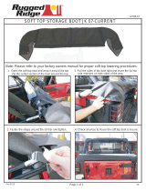
Clearview Blue Cassette
Installation Manual ______________________________________________________
Manual 019389 Rev H - May 2021

Direct: 763.476.6866 • National: 800.422.2537 • www.SeeCleareld.com • [email protected]
2
Clearview Blue Cassette
Installation Manual _________________________________________________________
Manual 019389 Rev H - May 2021
Table of Contents
Application 3
Description 3
Technical Specications 3
Congurations 4
Accessing the Cassette 6
Cable Entrance Method: Standard Entrance 8
Loose Tube 8
Tight Buffer 10
Ribbon 12
Cable Entrance Method: Slack Storage 14
Loose Tube 14
Ribbon 21
Splicing in the Cassette: Loose Tube 23
12 Fiber Loose Tube Splice 23
Right Rear Redirect 26
24 Fiber Loose Tube Splice 29
Expansion Ring 34
Splicing in the Cassette: Ribbon 35
12 Fiber Singe Ribbon Splice 35
24 Fiber Double Ribbon Splice 37
Mounting Options 42
Mounting Ears 42
Ganging Bracket 45
Ganging Cassettes 47
Removing the Adapter Plate/Testing 48
Connector Cleaning Procedure 49
Standard Warranty 52
Proprietary Notice 53
Technical Support 53

3
Clearview Blue Cassette
__________________________________________________________ Installation Manual
Direct: 763.476.6866 • National: 800.422.2537 • www.SeeCleareld.com • [email protected]
Manual 019389 Rev H - May 2021
Clearview Blue Cassettes are a core building block of every product within the FieldSmart® ber management system.
Clearview Blue continues to incorporate exibility and scalability, now with enhanced conguration options including
tool-less installation, in-cassette buffer tube/ribbon slack storage, and front access-only designs. Reducing the overall
footprint of the ber management element reduces real estate costs and improves density without compromising critical
design elements of access, bend-radius protection, physical ber protection and route-path diversity.
Clearview Blue is a six component tool-less system made up of a top cover, expansion ring, splice tray, buffer tube/
ribbon slack storage, cable assembly tray and 12-pack adapter plate. Parts snap together to support desired application
requirements. All types of ber cable construction can be integrated within the cassette to support all patch and splice, patch
only, passive optical component hardware and plug-and-play scenarios.
Technical Specications
Deployed with SC or LC connectors for 12-24 ports of connectivity, a single the Clearview
Blue Cassette provides for patch and splice (Cleareld’s in-cassette splicing solution),
patch only (stubbed) or plug-and-play (MPO/MTP) congurations in any network
environment. A dual high 24 ber Cassette offers additional splicing capacity for SC port
count requirements greater than 12, utilizing the Clearview Expansion Ring to provide
further exibility and scalability within the same footprint. Dual MPO/MTP access is
available on either side of the cassette. Additional optical components integrate into the
cassette housing, supporting any input/output combination of splitting, mux, and demux
strategies desired.
Deployed with the CS® Connector, the Clearview Blue Cassette provides 48 ports of ultra high-density connectivity. Using
the same 1.25mm ferrules, this adapter conguration provides 33% more density than the traditional LC connector cassette,
oubling the density for Clearview-enabled wall boxes, panels, cabinets and pedestals. Providing a plug-and-play
(MPO/MTP) conguration for any network environment, dual MPO/MTP access is available on either side of the cassette.
Description
Application
Clearview Blue Cassette
Dimension Without Mounting Ears: 0.81” H x 6.03” W x 8.28” D
With Mounting Ears: 0.81” H x 8.66” W x 8.28” D
Ratings Terminations are designed and tested to Telcordia GR-326; Tested to GR-63 NEBS 3 and UL94 V-0; Cleareld
FiberDeep Guartantee: 0.2 dB insertion loss or less, exceeding industry standards
Backwards
Compatible Optional mounting ears for backwards compatibility to FieldSmart inside plant (FxDS), OSP and access product lines
Material Polycarbonate
Connector Types Supports industry standard SC, LC, ST, FC and MPO singlemode and multimode connectors
Meters/Feet of
SlackStorage Up to 10 feet of buffer tube storage in the bottom of the cassette; one meter of 250 μm used for internal splicing
Mounting Options Clearview Building Block or Clearview Mounting Ears

Direct: 763.476.6866 • National: 800.422.2537 • www.SeeCleareld.com • [email protected]
4
Clearview Blue Cassette
Installation Manual _________________________________________________________
Manual 019389 Rev H - May 2021
Congurations
Patch and Splice: Loose Tube
The Clearview Blue cassette offers integrated patch and splice applications via a built-in splice tray. The cassette is
pre-loaded with a one meter 250μm loose tube ber assembly which is pre-terminated and slack stored inside the cassette
for splicing. Utilizing the dual snap-in splice chip option, 24 splices can be performed inside the cassette. Additionally, there
is area to store up to 10 feet of buffer tube storage with 8 cable entry/exit locations for the maximum in exibility.
24 Fiber Loose Tube Patch and Splice
Patch and Splice: Ribbon
The Clearview Blue cassette offers integrated patch and splice applications via a built-in splice tray. The cassette is
pre-loaded with a one meter 250μm ribbon ber assembly which is pre-terminated and slack stored inside the cassette for
splicing.
Single Ribbon Patch and Splice Dual Ribbon Patch and Splice
12 Fiber Loose Tube Patch and Splice

5
Clearview Blue Cassette
__________________________________________________________ Installation Manual
Direct: 763.476.6866 • National: 800.422.2537 • www.SeeCleareld.com • [email protected]
Manual 019389 Rev H - May 2021
Patch Only
Regardless of the industry standard adapters or cable construction, the
Clearview Blue handles all patch only applications using the lower tray, top
cover, built in radius limiter and removable adapter plate.
Optical Components
Clearview Blue integrates optical components into the identical cassette,
allowing service providers to mix and match ber modules with optical
components in the same chassis. The front faceplate is secured to reduce
chance of accidental damage to the optical component.
Plug-and-Play
MPO to 12-ber 900 μm assembly allows for plug-and-play by mating
MPO to MPO with pre-terminated multi-ber OSP or IFC. Also available in
dual-MPO, 24 ber congurations.
Patch and Splice - 2 High
For port count requirements greater than 12, the 24 port SC Expansion
cassette allows 24 splices to be performed in a single modular unit, while
using non-LC connectors. Utilizing the Clearview Expansion Ring, the
cassette is doubled in height allowing for 24 ports of connectivity.
CS® Connector
48 ports of ultra high-density connectivity, with 33% more density than the tradition-
al LC connector cassette. Providing a plug-and-play (MPO/MTP) conguration for
any network environment, dual MPO/MTP access is available on either side of the
cassette.

Direct: 763.476.6866 • National: 800.422.2537 • www.SeeCleareld.com • [email protected]
6
Clearview Blue Cassette
Installation Manual _________________________________________________________
Manual 019389 Rev H - May 2021
Accessing the Cassette
The Clearview Blue Cassette is capable of being used in a multitude of applications. Based on each individual application,
the cable entrance points and method of slack storage are different.
• Splicing loose tube or ribbon utilizing the standard entrance
• Splicing loose tube ber utilizing the lower level buffer tube storage
• Splicing ribbon ber utilizing lower level ribbon storage
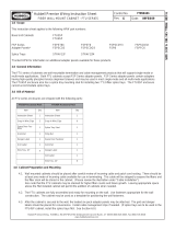
The Clearview Blue Cassette will arrive as shown, including a strain relief boot, as well as mounting ears and retaining
screws/plungers depending upon the conguration.
Top View Bottom View
Remove the top cover by pressing the locking tabs underneath the arrows on both sides of the cover, and lifting away.1.

7
Clearview Blue Cassette
__________________________________________________________ Installation Manual
Direct: 763.476.6866 • National: 800.422.2537 • www.SeeCleareld.com • [email protected]
Manual 019389 Rev H - May 2021
The splice tray cover can be removed by
lifting on the two ears at the bottom of the
splice tray cover.
Note: For loose tube cassettes the ber
pigtail inside is composed of a ribbon that
has been delaminated and fanned out.
2.

Direct: 763.476.6866 • National: 800.422.2537 • www.SeeCleareld.com • [email protected]
8
Clearview Blue Cassette
Installation Manual _________________________________________________________
Manual 019389 Rev H - May 2021
Cable Entrance Method: Standard Entrance
In a situation where the lower slack storage is not desired, buffer tube can be brought into the top of the splice tray. Shown
below is a “left exit” conguration. Simply secure the buffer tube to the other side of the splice tray for a “right exit”.
Note: Standard exit/entrance is determined looking from the back of the cassette.
Slide the strain relief boot over the end of the buffer
tube and push it down the tube over 3 feet.
Measure 3 feet back from the end of the buffer tube
and mark the tube with a permanent marker.
Wrap one layer of grommet tape around the buffer
tube behind your mark, and trim the excess. This will
help protect the buffer tube when it is secured into the
cassette.
Note: More than one lap of grommet tape may not
allow the cover to close properly and lie at.
Remove the outer jacket of the buffer tube at the
mark you made.
1.
2.
3.
4.
Loose Tube

9
Clearview Blue Cassette
__________________________________________________________ Installation Manual
Direct: 763.476.6866 • National: 800.422.2537 • www.SeeCleareld.com • [email protected]
Manual 019389 Rev H - May 2021
Slide up the boot and push it into the boot
retainer at the standard entrance.
Secure the buffer tube down with the cable
tie. Trim the excess.
Note: If using the “right” exit, the ber will
need to be redirected. Refer to the Right
Rear Redirect section on page 26 for
special routing instructions.
Proceed to the loose tube splicing section of
this manual.
6.
7.
8.
Insert a cable tie (or piece of wax string) into
the desired tie-down holes at the top of the
cassette.
5.

Direct: 763.476.6866 • National: 800.422.2537 • www.SeeCleareld.com • [email protected]
10
Clearview Blue Cassette
Installation Manual _________________________________________________________
Manual 019389 Rev H - May 2021
Tight buffer cable will be secured into the cassette in a similar manner to loose tube ber. Shown below is a “left exit”
conguration. Simply secure the tight buffer cable to the other side of the splice tray for a “right exit”.
Note: Standard exit/entrance is determined looking from the back of the cassette.
1. Measure 30 inches back from the end of the tight
buffer cable and mark the cable with a permanent
marker.
Note: Due to the size of the cable, a strain relief
boot will not be used with tight buffer cable.
2. Remove the outer jacket from the cable at the mark
you made by carefully cutting a ring around the
outside.
3. Remove any extra material inside the cable until all that remains are the 900 micron tight buffer bers.
4. Insert a cable tie (or piece of wax string) into the
desired tie-down holes at the top of the cassette.
Tight Buffer

11
Clearview Blue Cassette
__________________________________________________________ Installation Manual
Direct: 763.476.6866 • National: 800.422.2537 • www.SeeCleareld.com • [email protected]
Manual 019389 Rev H - May 2021
5. Gently secure the cable into the cassette using the cable tie/wax string, trimming the excess.
Note: Take extra care not to secure the cable too tightly, as bers could be damaged.
6. After the cable is secured to the
cassette, coil the tight buffer bers in
the cassette and proceed to the loose
tube splicing section of this manual.
Note: Of the 30 inches of 900 micron
tight buffer ber exposed, 2 inches
will be stripped and used for splicing.
The other 28 inches will be stored
in the slack storage chamber of the
splice tray. Otherwise, splicing will
be performed in the same manner as
with loose tube ber.
Note: If using the “right” exit, the ber
will need to be redirected. Refer to
the Right Rear Redirect section on
page 26 for special routing
instructions.

Direct: 763.476.6866 • National: 800.422.2537 • www.SeeCleareld.com • [email protected]
12
Clearview Blue Cassette
Installation Manual _________________________________________________________
Manual 019389 Rev H - May 2021
Furcation Tubing
Cleareld recommends the use of furcation tubing to protect bare ribbon bers to be spliced into the cassette. Shown below
is a “left exit” conguration. Simply secure the furcation tube to the other side of the splice tray for a “right exit”.
Note: Standard exit/entrance is determined looking from the back of the cassette.
Ribbon
Slide the strain relief boot over the end of the
furcation tube.
Fold a piece of grommet tape over the tube
just behind the end, and trim the excess.
Feed 3 feet of ribbon ber out of the end of
the furcation tubing.
Insert a cable tie (or piece of wax string) into
the desired tie-down holes at the top of the
cassette
1.
2.
3.
4.
Slide up the boot and push it into the boot
retainer at the standard entrance
Secure the furcation tubing down with the
cable tie/wax string. Trim the excess.
Proceed to the ribbon splicing section of this
manual.
Note: If using the “right” exit, the ber will
need to be redirected. Refer to the Right
Rear Redirect section on page 26 for special
routing instructions.
5.
6.
7.

13
Clearview Blue Cassette
__________________________________________________________ Installation Manual
Direct: 763.476.6866 • National: 800.422.2537 • www.SeeCleareld.com • [email protected]
Manual 019389 Rev H - May 2021
Bare Ribbon
If you are bringing bare ribbon ber into the cassette, it will be secured into place using the provided ribbon tie-down. Shown
below is a “left exit” conguration. Simply secure the ribbon tie-down to the other side of the splice tray for a “right exit”.
Note: Standard exit/entrance is determined looking from the back of the cassette.
1. Place the strain relief boot over the end of the ribbon
ber, and slide the boot over 3 feet down the length of
the ber.
2.
3.
Slide the provided ribbon tie-down, soft tube side rst,
over the end of the ribbon.
Heat the ribbon tie-down into place 3 feet back from the
end of the ribbon.
Note: Never tie down bare, unprotected ribbon ber.
Insert a cable tie (or piece of wax string) into the desired
tie-down holes at the top of the cassette
4 .
Slide up the boot and push it into the boot retainer at
the standard entrance
Secure the ribbon tie-down with the cable tie/wax string.
Trim the excess.
Proceed to the ribbon splicing section of this manual.
Note: If using the “right” exit, the ber will need to be
redirected. Refer to the Right Rear Redirect section on
page 26 for special routing instructions.
5.
6.
7.

Direct: 763.476.6866 • National: 800.422.2537 • www.SeeCleareld.com • [email protected]
14
Clearview Blue Cassette
Installation Manual _________________________________________________________
Manual 019389 Rev H - May 2021
Identify which entrance port is to be used.
• Entrances 1L and 1R are used for the right and left
hand sides of the FxHD frame, respectively.
• Entrances 2L and 2R work well for the right and
left hand sides, respectively, of FxDS panels with
no rear protection.
• Entrances 3L and 3R are used in some wallboxes
and for special needs.
• Entrances 1L, 3L and 2R require the use of the
Right Rear Redirect in the splice tray, detailed on
page 26.
Note: A strain relief boot is shown in every location,
but the cassette will include only one.
2R
1R
1L
2L
3R
3L
Cable Entrance Method: Slack Storage
The Clearview Blue Cassette allows for roughly 8 feet of slack storage in its lower chamber. The pictures shown in this
section will mostly feature buffer tube as that is the most visible of the options. While ribbon can be stored in the slack
storage chamber, the use of furcation tubing up to the cassette entrance is required. Tight buffer cable will not be able to be
slack stored in the cassette due to the increased cable diameter.
1.
Loose Tube
Slide the included rubber strain relief boot onto the buffer
tube to be spliced as shown. Push the boot down the tube
and out of the way, it will be utilized later in the process.
2.

15
Clearview Blue Cassette
__________________________________________________________ Installation Manual
Direct: 763.476.6866 • National: 800.422.2537 • www.SeeCleareld.com • [email protected]
Manual 019389 Rev H - May 2021
Entrances 1L, 3L, 2R:
For cable entrances 1L, 3L, and 2R, insert the buffer tube to be spliced into the bottom of the cassette as shown. The buffer
tube will extend into the top of the splice tray through the transition hole in the splice tray.
Note: The ber will need to be redirected during splicing, refer to the Right Rear Redirect section on page 26 for special
routing instructions.
Bottom View Top View
Entrances 2L, 1R, 3R:
For cable entrances 2L, 1R, and 3R, insert the buffer tube to be spliced into the bottom of the cassette as shown. The buffer
tube will extend into the splice tray through the transition hole in the splice tray.
Bottom View Top View
Pass the buffer tube up through the bottom of the transition hole at the top of the cassette, pulling over 3 feet through.
3.

Direct: 763.476.6866 • National: 800.422.2537 • www.SeeCleareld.com • [email protected]
16
Clearview Blue Cassette
Installation Manual _________________________________________________________
Manual 019389 Rev H - May 2021
Measure three feet from the end of the buffer tube and
mark the jacket with a permanent marker.
Behind your mark, wrap one layer of grommet tape
around the buffer tube, and trim the excess. This will
help protect the buffer tube.
Note: More than one lap will not allow the cover to
close properly and lie at.
Insert a cable tie (or length of wax string) into the
tie-down holes at the top of the cassette which best t
your routing scheme.
Remove the outer jacket of the buffer tube at the mark
you made.
Secure the buffer tube with the cable tie and trim the
excess.
Note: Push the cable tie head down to the side so it
doesn’t stick straight up and prevent the covers from
closing properly.
Proceed to the loose tube splicing section of this
manual and return to the next step once you are ready
to store the remaining slack inside the cassette.
4.
5.
6.
7.
8.
9.

17
Clearview Blue Cassette
__________________________________________________________ Installation Manual
Direct: 763.476.6866 • National: 800.422.2537 • www.SeeCleareld.com • [email protected]
Manual 019389 Rev H - May 2021
Entrances 2L, 3R, 1R:
After splicing in the cassette, you will store your
buffer tube slack in the base of the cassette.
10.
Begin by routing the buffer tube in a counter-
clockwise spiral pattern, feeding the buffer tube
in as you go around to ensure the buffer tube is
pushed up at against the previous layer. The
slack storage tray can store up to 8 feet of buffer
tube.
Continue routing the buffer tube until you have
stored the desired amount.
Note: The buffer tube should lie at as it is
stored, try to prevent it from stacking on top of
itself.
11.
12.

Direct: 763.476.6866 • National: 800.422.2537 • www.SeeCleareld.com • [email protected]
18
Clearview Blue Cassette
Installation Manual _________________________________________________________
Manual 019389 Rev H - May 2021
After the desired amount of slack has been
stored, cross the buffer tube over the coil at
the top of the cassette and transition to the
outside track of the buffer tube storage tray.
For entrance 2L, the boot can then be slid up
and inserted into the boot retainer.
For entrance 1R, continue around the outside
exit track and place the boot in the retainer at
the exit.
For entrance 3R, continue further around the
exit track and place the boot in the retainer at
the exit.
13.
14.
15.
16.

19
Clearview Blue Cassette
__________________________________________________________ Installation Manual
Direct: 763.476.6866 • National: 800.422.2537 • www.SeeCleareld.com • [email protected]
Manual 019389 Rev H - May 2021
Entrances 1L, 3L, 2R:
After splicing in the cassette, you will store your
buffer tube slack in the base of the cassette.
10.
Begin by routing the buffer tube in a clockwise
spiral pattern, feeding the buffer tube in as you go
around to ensure the buffer tube is pushed up at
against the previous layer. The slack storage tray
can store up to 8 feet of buffer tube.
11.
Continue routing the buffer tube until you have
stored the desired amount.
Note: The buffer tube should lie at as it is
stored, try to prevent it from stacking on top of
itself.
12.

Direct: 763.476.6866 • National: 800.422.2537 • www.SeeCleareld.com • [email protected]
20
Clearview Blue Cassette
Installation Manual _________________________________________________________
Manual 019389 Rev H - May 2021
After the desired amount of slack has been
stored, cross the buffer tube over the coil at
the top of the cassette and transition to the
outside track of the buffer tube storage tray.
For entrance 2R, the boot can then be slid up
and inserted into the boot retainer.
13.
14.
For entrance 1L, continue around the outside
exit track and place the boot in the retainer at
the exit.
15.
For entrance 3L, continue further around the
exit track and place the boot in the retainer at
the exit.
16.
Page is loading ...
Page is loading ...
Page is loading ...
Page is loading ...
Page is loading ...
Page is loading ...
Page is loading ...
Page is loading ...
Page is loading ...
Page is loading ...
Page is loading ...
Page is loading ...
Page is loading ...
Page is loading ...
Page is loading ...
Page is loading ...
Page is loading ...
Page is loading ...
Page is loading ...
Page is loading ...
Page is loading ...
Page is loading ...
Page is loading ...
Page is loading ...
Page is loading ...
Page is loading ...
Page is loading ...
Page is loading ...
Page is loading ...
Page is loading ...
Page is loading ...
Page is loading ...
Page is loading ...
/