Page is loading ...

– 1 –
HR5 & HR7 ROTISSERIE OVENS
&
HW5 & HW7 WARMERS
MODELS
HR5
auto. controls ML-126454
ML-126727
prog. controls ML-126456
ML-126728
HR7
auto. controls ML-126455
ML-126725
prog. controls ML-126457
ML-126726
HW5 ML-126207
HW7 ML-126208
701 S. RIDGE AVENUE
TROY, OHIO 45374-0001
FORM 34046 Rev. B (7-99)
HR5 Oven/
HW5 Warmer
N
S
T
R
U
C
T
I
O
N
S
I

– 2 –
© HOBART CORPORATION, 1999
TABLE OF CONTENTS
MODELS............................................................................................................................................... 4
GENERAL............................................................................................................................................. 5
Features and Options .................................................................................................................... 5
Ovens.............................................................................................................................................. 6
Warmers ......................................................................................................................................... 6
INSTALLATION.................................................................................................................................... 7
Location .......................................................................................................................................... 7
Legs / Casters ................................................................................................................................7
Assembly ........................................................................................................................................ 7
Assembling the Drip Plate ....................................................................................................... 7
Assembling the Rotor (HR7 only)............................................................................................ 8
Electrical Connections ................................................................................................................. 10
Stacked Oven or Oven and Warmer..................................................................................... 10
Single Oven or Warmer ......................................................................................................... 10
Electrical Data ........................................................................................................................ 11
Before First Use ........................................................................................................................... 12
OPERATION ...................................................................................................................................... 12
Programmable Oven Control Panel With Manual Controls ....................................................... 13
Manual Controls........................................................................................................................... 14
Using Manual Controls .......................................................................................................... 14
Programmable Controls............................................................................................................... 15
Setting the Time of Day ......................................................................................................... 15
Programming Menu Buttons.................................................................................................. 16
Verifying Programmed Temperatures and Times ................................................................ 16
Starting a Processing Cycle .................................................................................................. 17
Displaying Time/Temperature During a Process Cycle....................................................... 17
Interrupting a Process Cycle ................................................................................................. 17
End of Processing Cycle........................................................................................................ 17
Changing a Programmed Setting.......................................................................................... 17
Turning the Buzzer Off........................................................................................................... 18
Setting the End Time (Delayed Start)................................................................................... 18
Setting an Early Warning Buzzer .......................................................................................... 18
Stopping the Rotisserie.......................................................................................................... 18
Automatic Oven Control Panel With Manual Controls............................................................... 19
Manual Controls........................................................................................................................... 20
Using Manual Controls .......................................................................................................... 20

– 3 –
Automatic Controls....................................................................................................................... 21
Setting the Temperature........................................................................................................ 21
Setting the Roasting Time ..................................................................................................... 21
Setting an Early Warning Buzzer .......................................................................................... 22
Setting End Time (Delayed Start) ......................................................................................... 22
Interrupting an Automatic Cooking Operation...................................................................... 22
Stopping an Automatic Cooking Operation .......................................................................... 23
Changing a Setting ................................................................................................................ 23
Stopping the Rotisserie.......................................................................................................... 23
Setting the Time of Day ......................................................................................................... 23
Turning the Buzzer Off........................................................................................................... 23
Resetting the Automatic Controls ......................................................................................... 23
Preparing the Product.................................................................................................................. 24
Loading Products Onto Accessories........................................................................................... 24
Loading Products onto Spits ................................................................................................. 24
Loading Products onto Chicken Racks................................................................................. 25
Loading Products in a Basket................................................................................................ 26
Loading Accessories Into Oven .................................................................................................. 27
Loading Spits Into Oven ........................................................................................................ 28
Loading Fork Spits Into Oven................................................................................................ 28
Loading Racks, Baskets, or Backing Plates Into Oven ....................................................... 29
Unloading Accessories From Oven ............................................................................................ 29
Suggestive Roasting Guidelines ................................................................................................. 30
Emptying Grease Drawer ............................................................................................................ 31
Warmer Controls .......................................................................................................................... 32
Using Warmers (Models HW5 and HW7)................................................................................... 32
CLEANING ......................................................................................................................................... 33
Cleaning Stainless Steel Surfaces.............................................................................................. 33
Cleaning Nonstick Coated Surface............................................................................................. 33
How To Clean Nonstick Coated Surfaces (Routine Cleaning)............................................ 34
How to Clean Severe Buildup on Nonstick Coated Surfaces.............................................. 34
Cleaning Probe ............................................................................................................................ 34
Cleaning Grease Drawer ............................................................................................................. 35
Cleaning Warmers ....................................................................................................................... 35
Cleaning Quartz Lamps............................................................................................................... 35
Monthly Cleaning ......................................................................................................................... 35
MAINTENANCE ................................................................................................................................. 36
Model HR5 Only........................................................................................................................... 36
Service.......................................................................................................................................... 36

– 4 –
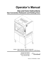
Model HR5 Oven
Model HW5 Warmer
Model HR5 Oven/HW5 Warmer
Model HR7 Oven
Model HW7 Warmer
Model HR7 Oven/HW7 Warmer
• Rotisserie Ovens with Programmable Controls shown; Meat probe not shown.

– 5 –
Installation, Operation and Care of
HR SERIES ROTISSERIE OVENS AND
HW SERIES ROTISSERIE WARMERS
PLEASE KEEP THIS MANUAL FOR FUTURE REFERENCE
GENERAL
The Hobart HR Series Rotisserie Ovens and HW Series Rotisserie Warmers feature full view tempered
glass doors, both front and back, and quartz lighting that promotes visual appeal and stimulates
customer interest. They also feature a stainless steel interior and exterior for ease of cleaning.
Ovens and Warmers are available in two sizes:
HR5 — Oven with five spits (15-20 chickens)
HW5— Warming cabinet
HR7 — Large oven with seven spits (28-35 chickens)
HW7— Warming cabinet
DO NOT mix accessories on the rotor.
Stacking kits are available to stack ovens or stack an oven and warmer. You must stack the same size
oven and warmer. Refer to the Stacking Kit Installation Instructions (F-24860) for further information.
Features and Options
Quantity Required per Oven
Spit Basket Turkey Spit Baking Plate Chicken Rack Meat Forks Warmer Shelves
3 rack 4 rack 5 rack
HR5 5 std. 5 opt. 1 opt. 5 opt. 5 opt. NA NA 5 opt. NA
HR7 7 std. 7 opt. 1 opt. NA NA 7 opt. 7 opt. 7 opt. NA.
HW5 NA NA NA NA NA NA NA NA 3 std.
HW7 NA NA NA NA NA NA NA NA 3 std.

– 6 –
OVENS
There are two types of oven control operations:
• Programmable with Manual control operation
• Automatic with Manual control operation
When you purchase your rotisserie oven you have the option of ordering the rotor, drip plates, and
some accessories with either a nonstick coated surface or stainless steel surface. Refer to the next
page to assemble the drip plate and rotor.
The HR ovens use self-basting spits with optional flat baking racks, meat forks, or baskets. The rotation
of the spits, racks, or baskets with the combination convection and radiant heat provide thorough
cooking and even browning in the oven. The oven's grease drawer has a drain valve for elimination
of excess fat and can be completely removed for cleaning.
WARMERS
The HW warmers feature low velocity, high humidity air circulation which keeps foods moist. The HW
warming cabinets have three shelves.

– 7 –
INSTALLATION
Immediately after unpacking the oven, check for possible shipping damage. If oven is found to be
damaged after unpacking, save the packaging material and contact the carrier within 15 days of
delivery.
Prior to installation, test the electrical service to assure that it agrees with the specifications on the
machine data plate located on the right side panel near the controls.
LOCATION
The oven may be placed where cooking may be observed to enhance customer awareness, but must
be installed on a level surface if the oven or warmer is not on casters.
The installation location must allow adequate clearances for servicing and for proper operation of the
front and rear doors.
• A minimum wall clearance of 10" (254 mm) from any glass, and 4" (101.6 mm) from each side panel
must be maintained.
LEGS / CASTERS
Each oven and warmer is furnished on 1
9
⁄16" (39.7 mm) legs. Casters are included with the stacking kit.
ASSEMBLY
The drip plate and rotor come in a separate boxed kit with either a nonstick coated surface or stainless
steel surface. They must be assembled at installation.
CAUTION: Special care must be taken when assembling coated parts. Any abrasion reduces
the life of the coated parts.
Assembling the Drip Plate
Place the two bottom drip plates in oven. The two plates slant to the middle to allow fat to drip into the
grease drawer (Fig.1).
Fig. 1
PL-41161

– 8 –
Assembling the Rotor (HR7 only)
You should have: (2) rotor end plates; (1) rotor shaft; (12) screws
1. Face the two rotor end plates against each other to make sure the holes match. This is done to
ensure you have a matched set of rotor end plates. If holes do not match, the accessories will
not align properly.
2. Align the holes on the left rotor end plate (as you face the rotor) with the holes on one side of the
rotor shaft.
3. Secure the rotor end plate to the rotor shaft with the screws available (Fig. 2).
HR7
Fig. 2
4. Assemble the right rotor end plate (as you face the rotor).
5. Align the hole pattern with the assembled left rotor end plate as indicated by the dotted lines
shown below (Fig. 3). This is done to ensure the rotor end plate is in the correct position.
6. Repeat steps 2 and 3 to secure the right rotor end plate.
HR7
Fig. 3
PL-53377
RIGHT HAND
ROTOR END PLATE
ROTOR SHAFT
LEFT HAND
ROTOR END PLATE
PL-53376
LEFT HAND
ROTOR END PLATE
ROTOR SHAFT

– 9 –
7. Place the assembled rotor in the oven.
8. Turn Rotisserie dial to to rotate rotor.
9. Turn Rotisserie dial to "0/P" to stop rotation when the hole pattern (Fig. 4) is located at the bottom
of the oven.
10. Verify that the hole pattern is identical to the top illustrated hole pattern shown in Fig. 4.
11. If hole pattern does not match the top illustrated hole pattern, but does match the bottom
illustrated hole pattern in Fig. 4:
a. Take rotor assembly out of oven.
b. Flip rotor assembly.
c. Place rotor assembly back in oven.
d. Repeat steps 8-10 above.
HR7
Fig. 4
PL-53381

– 10 –
ELECTRICAL CONNECTIONS
WARNING: ELECTRICAL AND GROUNDING CONNECTIONS MUST COMPLY WITH THE
APPLICABLE PORTIONS OF THE NATIONAL ELECTRICAL CODE AND/OR OTHER LOCAL
ELECTRICAL CODES.
WARNING: DISCONNECT ELECTRICAL POWER SUPPLY AND PLACE A TAG AT THE DISCONNECT
SWITCH INDICATING THAT YOU ARE WORKING ON THE CIRCUIT.
WARNING: APPLIANCES EQUIPPED WITH A FLEXIBLE ELECTRIC SUPPLY CORD ARE
PROVIDED WITH A THREE-PRONG GROUNDING PLUG. THIS PLUG MUST BE CONNECTED
INTO A PROPERLY GROUNDED THREE-PRONG RECEPTACLE. IF THE RECEPTACLE IS NOT
THE PROPER GROUNDING TYPE, CONTACT AN ELECTRICIAN. DO NOT REMOVE THE
GROUNDING PRONG FROM THIS PLUG.
Access the electrical connection point by removing the side panel(s) where the controls are located.
Ensure that the electrical power supply agrees with the specifications on the oven's data plate and
complies with the wiring diagram, located behind the oven side panel and under the drive motor.
Stacked Ovens or Oven and Warmer
Refer to the Stacking Kit Installation Instruction (F-24860) included with your stacking kit.
Single Oven or Warmer
1. Remove the side panels.
2. At the same time attach power leads to oven or warmer terminal block as shown on the wiring
diagram, located behind the side panel and under the drive motor, and attach the power supply
conduit to the bottom of the oven or warmer.
3. Attach power supply leads to line side of the terminal block.
4. Inspect and check all wiring and terminal connections for tightness and proper routing away from
any moving parts or pinch points.
5. Carefully replace the side panels.
Refer to the Electrical Data chart on the next page.

– 11 –
ELECTRICAL DATA
MODEL VOLTS HERTZ PHASE CIRCUIT SIZE*
(AMPS)
HR5 208 60 1 35
208 60 3 20
240 60 1 35
240 60 3 20
HR7 208 60 1 60
208 60 3 35
240 60 1 60
240 60 3 35
HW5 208 60 1 15
208 60 3 10
240 60 1 15
240 60 3 10
HW7 208 60 1 15
208 60 3 15
240 60 1 20
240 60 3 15
STACKED MODELS
(2) HR5 208 60 1 70
208 60 3 40
240 60 1 70
240 60 3 45
(2) HR7 208 60 3 70
240 60 3 70
(2) HW5 208 60 1 30
208 60 3 -
240 60 1 35
240 60 3 -
(2) HW7 208 60 1 30
208 60 3 25
240 60 1 40
240 60 3 30
HR5 & HW5 208 60 1 50
208 60 3 40
240 60 1 50
240 60 3 40
HR7 & HW7 208 60 1 80
208 60 3 50
240 60 3 80
240 60 1 50
* Maximum Circuit Breaker Size / Minimum Circuit Amperage compiled in accordance with the
National Electrical Code, 1990 edition.

– 12 –
BEFORE FIRST USE
WARNING: DISCONNECT ELECTRICAL POWER BEFORE CLEANING.
Oven must be "burned in" to release any odors that might result from heating the new oven surfaces.
1. Clean oven, accessories, and warmer (if present), both inside and outside, with warm soapy
water. Refer to "Cleaning" in this manual for further instructions.
2. Rinse thoroughly and wipe dry with a soft clean cloth. Avoid water contact with quartz lamps.
3. Operate oven at maximum temperature setting of 480°F (249°C) for 45 minutes. Smoke with an
unpleasant odor will normally be given off during this burn-in period.
OPERATION
WARNING: HOT GLASS, GREASE, AND PARTS CAN CAUSE BURNS. USE CARE WHEN
OPERATING AND SERVICING THE OVEN.
There are two types of oven controls:
• Programmable with Manual Controls
• Automatic with Manual Controls

– 13 –
PROGRAMMABLE OVEN CONTROL PANEL WITH MANUAL CONTROLS (Fig. 5)
Display
Shows temperature (°F) and time (HH:MM) when first turned on.
Colon flashes, remaining cooking time shows.
Programmable Controls
Set all control dials to "P". See pages 15-18.
Manual Controls
Use control dials. See page 14.
DISPLAY
PROGRAMMABLE
CONTROLS
THERMOSTAT
DIAL
ROTISSERIE
DIAL
MAIN POWER
DIAL
PL-53362
Manual
Controls
Fig. 5

– 14 –
MANUAL CONTROLS (Fig. 5)
Use control dials on the Programmable Control Panel.
Thermostat Dial
0°F – Heat is OFF.
Temperature settings – 150°F - 480°F (66°C - 249°C).
Rotisserie Dial
"0/P" – Rotisserie is OFF or in Programming Mode.
– Oven operates without restrictions.
– Customer heating lamp remains on, operator heating lamp cycles on and off to maintain the
desired temperature.
– Oven OFF, only rotor moves.
– Use to load and unload accessories.
– Oven operating.
– Customer heating lamp remains off, operator heating lamp cycles on and off for longer
cooking.
– Oven operating to keep food warm.
– Both heating lamps remain off.
Main Power Dial
"0" – Power is OFF
– Manual Mode
"P" – Programming Mode
Using Manual Controls
1. Set Main Power Dial to .
2. Set Thermostat Dial to your desired temperature setting. The operator heating lamp remains on
until the desired temperature is reached in the oven.
3. Set Rotisserie Dial to your desired manual setting.

– 15 –
PROGRAMMABLE CONTROLS (Fig. 6)
All programming must be done with all dials in the "P" position (Thermostat , Rotisseries, and Main
Power dials). If all dials are not set to "P", the manual controls override the programmable controls.
The programmable control allows you to program three different functions for each of the 5 menu
buttons. The three functions are Cook, Grill, and Warm/Hold.
• Cook cycle is for roasting. Cook time range is 1 hour to 1 hour and 30 minutes.
• Grill cycle is for searing and browning.
• Warm/Hold cycle is a holding cycle.
- Recommended holding temperature is 160°F (71°C) or 180°F (82°C).
- Rotisserie will continue to turn during the hold cycle.
Fig. 6
Setting the Time of Day
1. Turn Main Power dial to "P".
2. Press and hold and adjust to current time by using or . This is a 12-hour clock.
The actual time of day may be viewed on the display at any time, except during a running process, by
pressing .
PL-41185-1
TIME OF
DAY
PROCESS
INDICATORS
POWER
INDICATOR
START / STOP
BUTTON
WARM / HOLD
PROCESS
PROGRAM
INDICATORS
PROGRAM
KEYS
BUZZER
UP
TEMPERATURE
TIME
DOWN
GRILL
PROCESS
PROGRAM
END
PROBE
ROTOR
COOKING
PROCESS

– 16 –
Programming Menu Buttons
1. Before entering the program mode, you must first press a Menu Button. Press Menu Button #1.
Its LED will light.
2. To enter Program mode, press and hold both and simultaneously until time display
shows "PROG" (approximately 2 seconds). The LED on Menu Button #1 and Cooking Process
Indicator will start blinking.
3. Cook function time and temperature must be programmed first.
Press and hold while pressing or to adjust to temperature desired.
• Maximum allowable temperature setting is 480°F (249°C); minimum is 32°F (0°).
Press and hold while pressing or to adjust to time desired.
• Maximum time setting is 5 hours, 59 minutes.
4. Program the Grill function for Menu Button #1.
Press . The Grilling Process Indicator and LED on Menu Button #1 will start blinking.
Press and hold while pressing or to adjust to temperature desired.
• Maximum allowable temperature setting is 480°F (249°C); minimum is 32°F (0°C).
Press and hold while pressing or to adjust to time desired.
5. Program the Warm/Hold function for Menu Button #1.
Press . The Warm/Hold Process Indicator and LED on Menu Button #1 will start blinking.
Press and hold while pressing or to set temperature for the hold cycle.
You cannot program a time for the warm/hold function. If you try to program a time, the buzzer
will sound for 3 seconds, then shut off. After programming of Menu Button #1 is completed, the
time display will show the current time of day.
6. Press flashing Menu Button #1 to lock in the programmed settings.
After programming, the display will show the time and temperature programmed for the Cook
function. If you have programmed "0" time and minimum temperature (32°F [0°C]) for the Cook
function, the displays will show the actual cavity temperature and actual time of day.
7. Continue programming Menu Buttons 2-5 in the same manner. All functions must have a value
entered to allow the program to work properly.
Verifying Programmed Temperatures and Times
Cook function: Press and hold the desired Menu Button, then press
.
Grill function: Press and hold the desired Menu Button, then press
.
Warm/Hold: Press and hold the desired Menu Button, then press
.
• Only the temperature will be displayed in the Warm/Hold function.
• Time display will show "00:00".

– 17 –
Starting a Processing Cycle
1. Press desired Menu Button (its LED will light).
2. Press (its LED will light).
• Time display will show total processing time and will count down to the end of the
processing cycle.
• Temperature display will show pht (preheat) until oven cavity temperature reaches 125°F
(52°C). Then it will show the actual cavity temperature while maintaining the programmed
temperature.
Displaying Time/Temperature During a Processing Cycle
— If pressed during a processing cycle, probe icon under temperature display will light
and probe temperature will be displayed for 20 seconds. You may press it again if
you like.
— Press and hold to display both Cook temperature and time programmed for the Menu Button
you're using.
— Press and hold to display both Grill temperature and time programmed for the Menu Button
you're using.
— Press and hold to display programmed temperature only.
— Press and hold to display programmed time only.
Interrupting a Processing Cycle
1. Press if you want to check the food before the end of the processing cycle.
• This will turn off the heaters, front lamp (customer side), and rotor will flash.
2. Press again to start cycle from where it left off.
3. Press to start all over at the beginning of programmed cycle.
End of Processing Cycle
At the end of a Cook or Grill cycle, a buzzer will sound. Press to silence the buzzer.
When oven goes into Warm/Hold cycle, the buzzer will sound and operator side lamp will cycle on and
off with heaters.
• Press and hold to silence buzzer.
• The temperature and time displays will show actual oven cavity temperature and time of day until
reaching holding temperature.
• Press to end holding process.
Changing a Programmed Setting
You may modify temperature or time of a Cook or Grill function only on any Menu Button prior to
starting processing, or during processing.
• Press (for temperature) or (for time) while pressing or .
• This will not change the temperature or time programmed in the memory for that Menu Button.

– 18 –
Turning the Buzzer Off
Press .
Setting the End Time (Delayed Start)
Assume roasting time is one hour and fifteen minutes and it is currently 2 o'clock. If you want to finish
roasting at 4:00, program as follows:
1. Press and hold while pressing or to adjust the time to 4:00.
• Colon in display will flash.
• Time display will show cooking time.
2. Press .
• Cooking will begin at 2:45. Colon starts flashing.
• Roasting stops at 4:00; buzzer sounds. Press to silence.
If after pressing the end time comes earlier than the current time + the program time, a beep will
sound (for three minutes) and program will not start.
• Programmed end time is now cancelled.
• When is pressed again, program starts in the normal way.
Setting an Early Warning Buzzer
You can program an early warning buzzer for basting or whatever reason.
• This function is completely independent of any program, whether it is running or not.
• Buzzer always sounds for three minutes.
1. Press when buzzer is not engaged, the current time or the already programmed time will
be shown in the display.
2. Press or and at the same time to program the moment when the beep tone will
sound.
• Minimum is the current time.
• Maximum is the current time minus 1.
• Buzzer delay time can always be changed as long as the beep tone has not sounded.
• As soon as a beep tone sounds as a result of the elapsed buzzer delay time, the programming
is cancelled.
Stopping the Rotisserie
Press .
• Heaters, operator side lamp, and rotisserie will turn off.
• To start rotisserie again, see procedures described under "Interrupting a Processing Cycle".

– 19 –
AUTOMATIC OVEN CONTROL PANEL WITH MANUAL CONTROLS (Fig. 7)
Display
Shows temperature (°F) and time (HH:MM) when first turned on.
Colon flashes, remaining cooking time shows.
Automatic Controls
Set all control dials to "P". See pages 21-23.
Manual Controls
Use control dials. See page 20.
DISPLAY
THERMOSTAT
DIAL
ROTISSERIE
DIAL
MAIN POWER
DIAL
AUTOMATIC
CONTROLS
PL-53361
Manual
Controls
Fig. 7

– 20 –
MANUAL CONTROLS (Fig. 7)
Use control dials on the Automatic Control Panel.
Thermostat Dial
0°F – Heat is OFF.
Temperature settings – 150°F - 480°F (66°C - 249°C).
Rotisserie Dial
"0/P" – Rotisserie is OFF or in Automatic Mode.
– Oven operates without restrictions.
– Customer heating lamp remains on, operator heating lamp cycles on and off to maintain the
desired temperature.
– Oven OFF, only rotor moves.
– Use to load and unload accessories.
– Oven operating.
– Customer heating lamp remains off, operator heating lamp cycles on and off for longer
cooking.
– Oven operating to keep food warm.
– Both heating lamps remain off.
Main Power Dial
"0" – Power is OFF
– Manual Mode
"P" – Automatic Mode
Using Manual Controls
1. Set Main Power Dial to .
2. Set Thermostat Dial to your desired temperature setting. The operator heating lamp remains on
until the desired temperature is reached in the oven.
3. Set Rotisserie Dial to your desired manual setting.
/