
PRODUCT DATA
63-2587-1
N20, N34 Series MN7220, MN7234
NON-SPRING RETURN DAMPER ACTUATOR
20/34 Nm (175/300 lb-in) FOR MODULATING CONTROL
GENERAL
These direct-coupled damper actuators provide modulating
control for:
• rotary valves,
• air handling units,
• ventilation flaps,
• louvers, and
• reliable control for air damper applications with up to 50
sq.ft. (20 Nm / 175 lb-in) or 85 sq. ft. (34 Nm / 300 lb-in)
(seal-less damper blades; air friction-dependent).
FEATURES
• New self-centering shaft adapter
• Access cover to facilitate connectivity
• Declutch for manual adjustment
• Mechanical end limits (MN7220 only)
• Field-installable auxiliary switches
• Rotation direction selectable by switch
• Mountable in any orientation (no IP54 if upside down)
• Mechanical position indicator
SPECIFICATIONS
Supply voltage 24 Vac ±20%, 50/60 Hz;
24 Vdc -10...+20%
Nominal voltage 24 Vac, 50/60 Hz; 24 Vdc
All values stated hereinafter apply to operation under
nominal voltage conditions.
Power consumption
MN7220 6 VA / 6 W
MN7234 8 VA / 6 W
Ambient limits
Ambient operating limits -5...+140 °F (-20...+60 °C)
Ambient storage limits -40...+175 °F (-40...+80 °C)
Relative humidity 5...95%, non-condensing
Safety
Protection standard IP54 (non-USA models)
NEMA2 (USA models)
Protection class II as per EN 60730-1
Overvoltage category II
Lifetime
Full strokes 60000
Repositions 1.5 million
Mounting
Round damper shaft 3/8...1-1/16” (10...27 mm)
Square damper shaft 3/8...11/16” (10...18 mm);
45° steps
Shaft length min. 7/8” (22 mm)
Control signal 0(2)...10 Vdc
0(4)...20 mA
Input impedance 100 kΩ [0...10 V]
500 Ωm [0...20 mA]
Feedback signal
Limits ± 1 mA at 0...10 V
Auxiliary switch (when included)
Rating 5 A (resistive) / 3 A (inductive)
Triggering points 5° / 85°
Torque rating
MN7220 175 lb-in (20 Nm)
MN7234 300 lb-in (34 Nm)
Runtime 95 sec (60 Hz) / 110 sec (50 Hz)
Rotation stroke 95° ± 3°
Dimensions see “Dimensions” on page 8
Weight 3 lbs. (1.35 kg)
Noise rating 40 dB(A) max. at 1 m

N20, N34 SERIES MN7220, MN7234
63-2587—1 2
ORDERING INFORMATION
When purchasing replacement and modernization products from your TRADELINE® wholesaler or distributor, refer to the
TRADELINE® Catalog or price sheets for complete ordering number.
If you have additional questions, need further information, or would like to comment on our products or services, please write or
phone:
1. Your local Honeywell Automation and Control Products Sales Office (check white pages of your phone directory).
2. Honeywell Customer Care
1885 Douglas Drive North
Minneapolis, Minnesota 55422-4386
In Canada—Honeywell Limited/Honeywell Limitée, 35 Dynamic Drive, Scarborough, Ontario M1V 4Z9.
International Sales and Service Offices in all principal cities of the world. Manufacturing in Australia, Canada, Finland, France,
Germany, Japan, Mexico, Netherlands, Spain, Taiwan, United Kingdom, U.S.A.
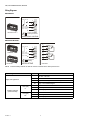
MODELS
Fig. 1. Product Identification System
OPERATION/FUNCTIONS
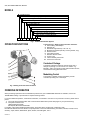
Fig. 2. Setting units and control elements
Legend for Fig. 2. Setting units and control elements:
1. Self-centering shaft adapter
2. Retainer clip
3. Rotational angle scales (0...90° / 90...0°)
4. Mechanical end limits (20 Nm [175 lb-in] models, only)
5. Declutch button
6. Anti-rotation bracket
7. Rotation direction switch
8. Access cover
9. Internal auxiliary switch wire
10. Power and control wire
Contents of Package
The delivery package includes the actuator itself, parts 1
through 10 (see Fig. 2; in the case of U.S. models – e.g.
MN7220 – parts 1 through 8), the anti-rotation bracket screws,
and the SM mounting plate and screws.
Modulating Control
The actuator is capable of being operated by several
controllers providing Vdc or mA output.
M – Electrical motor
N – Fail Safe Function (Non-Spring Return)
61 – 24V Floating Control
72 – 24V Modulating Control
20 – 20 Nm (175 lb-in)
34 – 34 Nm (300 lb-in)
A – Standard Model
1 – No Feedback
2 – Voltage Feedback Signal
0 – No Internal Auxiliary Switches
2 – Two Internal Auxiliary Switches
XX – System Controlled Numbers
MN7220A20XX

N20, N34 SERIES MN7220, MN7234
3 63-2587—1
Rotary Movement
The control signal and the corresponding rotation direction
(clockwise or counterclockwise) can be selected using the
rotation direction switch (see part Rotation direction switch in
Fig. 2), thus eliminating the need to re-wire. To ensure tight
closing of the dampers, the actuator has a total rotation stroke
of 95°.
As soon as operating power is applied, the actuator may start
to run. When power is removed, the actuator remains in
position. For actuator-controller wiring instructions, see section
“Wiring” on page 5.
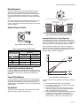
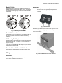
Rotation Direction Switch
Fig. 3. Rotation Direction Switch
Feedback Signal and Manual Adjustment
If, while the actuator is not rotating, the user declutches it and
manually repositions the shaft adapter, the feedback signal will
then follow the new position at which the shaft adapter has
been left.
Power Off/On Behavior
In case the power to the actuator fails, after re-applying power,
the actuator acknowledges its present position and follows the
signal from the controller. This makes it unnecessary for the
actuator to employ autoadaption in order to re-map the control
signal settings.
Dip Switches
The actuators are equipped with two dip switches accessible
after removing the access cover (see Fig. 4).
Fig. 4. Dip switches (view with PCB at bottom)
Autoadapt Dip Switch for Normal Operation
In its default shipping position, the autoadapt dip switch for
normal operation is set to ON as shown in Fig. 4. Dip switches
(view with PCB at bottom)4. If it is set to OFF, no autoadapting
is performed, and the control signal map remains constant.
The autoadapt functionality does not have to be triggered.
Rather, the SmartAct actuator does this automatically when the
min. and max. control signals are provided (see Fig. 5); the
feedback signal is likewise autoadapted.
Fig. 5. Actuator positioning curve
In order to make use of the autoadapt functionality, proceed as
follows:
1. Set the autoadapt dip switch to the ON position.
2. If necessary, limit the stroke to the desired range using
the mechanical end limits.
3. Drive the actuator to the left end limit (totally counter-
clockwise) by setting the control signal as specified in
Table 1. Feedback/control signal values1.
4. Drive the actuator to the right end limit (totally clockwise)
by setting the control signal as specified in Table 1.
Feedback/control signal values1. The stroke has now
been limited to 0...100% of the control signal range.
Table 1. Feedback/control signal values
Rotation direction
switch position
Feedback/control signal when
actuator is
totally totally
Y=2 /2...10V U = 2 V U = 10 V
Y=0 /0...10V* U = 0 V U = 10 V
Y=0 /10...0V U = 10 V U = 0 V
Y=2 /10...2V U = 10 V U = 2 V
* Default shipping position.
autoadapt dip switch for
normal operation ( )
ON
voltage/current control signal
dip switch ( )
OFF

N20, N34 SERIES MN7220, MN7234
63-2587—1 4
Voltage/Current Control Signal Selection Dip Switch
In its default shipping position, the voltage/current control
signal dip switch (see Fig. 4) is set to OFF (= voltage control).
as shown in Fig. 4. Setting it to ON results in current control.
Position Indication
The hub adapter indicates the rotation angle position by means
of the rotational angle scales (0...90° / 90...0°).
Fig. 6. Position indication
Manual Adjustment
IMPORTANT
In order to prevent equipment damage, you must
remove power before manual adjustment.
After removing power, the gear train can be disengaged using
the declutch button, permitting the actuator shaft to be
manually rotated to any position. The feedback signal will then
follow the new position.
Limitation of Rotation Stroke
Two mechanical end limits (adjustable in 3° increments) are
provided (20 Nm [175 lb-in] models, only) to limit the angle of
rotation as desired (see Fig. 7).
Fig. 7. Mechanical end limits
The mechanical end limits must be securely fastened in place
as shown in Fig. 8. Correct / incorrect tightening of end limits8.
Specifically, it is important that they properly mesh with the
rotational angle scales when the screws are tightened.
Fig. 8. Correct/incorrect tightening of end limits
Internal Auxiliary Switches
The internal auxiliary switches are set to change from
“common” to “normally open” at angles of 5° and 85°,
respectively, from the totally counterclockwise position.
Fig. 9. Internal auxiliary switches
Override
If terminal 3 of the terminal strip (see section “Wiring
Diagrams” on page 6) is unplugged, the stroke will be 0%;
reversing the rotation direction using the rotation direction
switch will result in a max. stroke of 100%. If terminal 3 is
jumped with terminal 1 (24 V), the stroke will be 50%.
INSTALLATION
These actuators are designed for single-point mounting.
IMPORTANT
In order to prevent equipment damage, you must
remove power or set the rotation direction switch to
the “Service/Off” position before manual operation.
Mounting Instructions
All information and steps are included in the Installation
Instructions supplied with the actuator.
90 90
60
30
60
30
00
5° 10° 15° 92.5
°
0° 90°-2.5° 85°80°75°
85° 80° 75° -2.5°90° 0°92.5° 5°10°15°
5° 10° 15°0° 90°85°80°75°
CCW internal
auxiliary switch
CW internal
auxiliary switch
actuator scale: clockwise
auxiliary switch scale
actuator scale: counterclockwise

N20, N34 SERIES MN7220, MN7234
5 63-2587—1
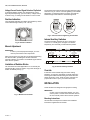
Mounting Position
The actuators can be mounted in any desired orientation (no
NEMA2 or IP54 if mounted upside down; see Fig. 10). Choose
an orientation permitting easy access to the actuator's cables
and controls.
Fig. 10. Mounting for IP54/NEMA2
Mounting Bracket and Screws
If the actuator is to be mounted directly on a damper shaft, use
the mounting bracket and screws included in the delivery
package.
Self-Centering Shaft Adapter
The self-centering shaft adapter can be used for shafts having
various diameters (3/8...1-1/16” [10...27 mm]) and shapes
(square or round).
In the case of short shafts, the shaft adapter may be reversed
and mounted on the duct side.
Stroke Limitation with Mechanical End Limits
The mechanical end limits (20 Nm [175 lb-in] models, only)
enable the stroke to be limited from 0...90° in increments of 3°.
Wiring
Access cover
To facilitate wiring the actuator to the controller, the access
cover can be detached from the actuator.
IMPORTANT
Remove power before detaching the access cover.
Once the access cover has been removed, please
take care to avoid damaging any of the parts now
accessible.
Fig. 11. Access cover
Depending upon the model, the access cover may have one or
two terminal strips, including a layout with a description for
each of the terminals.
Fig. 12. Actuator with access cover removed
NEMA2
IP54
NEMA2
IP54
NEMA2
IP54
NEMA2
IP54

N20, N34 SERIES MN7220, MN7234
63-2587—1 6
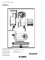
Wiring Diagrams
MN7220/MN7234
MN7220 WITH SWITCHES
NOTE: Internal auxiliary switches S1 and S4 must be connected to the same power source.
TERMINAL STRIP 1
MODULATING CONTROL
24 Vac 24 Vdc
0(2)...10 Vdc
0(4)...20 mA
0(2)...10 Vdc
~
1~
1
3Y
3Y
5U
5U
2
2
Connect via safety
isolating transformer!
!
connecting cable terminal name
supply and signal lines
1~
24 Vac∼ / 24 Vdc+
2⊥ 24 Vac⊥ / 24 Vdc-
3Y 0(2)...10 Vdc / 0(4)...20 mA control signal
5U 0(2)...10 V feedback signal
auxiliary switched
(when included)
CCW (left)
5°
S1 Common
S2 normally closed
S3 normally open
CW (right)
85°
S4 Common
S5 normally closed
S6 normally open
A
UXILIARY
S1
S2
S3
S4
S5
S6
S3
S2
S1
S6
S5
S4
A
UXILIARY
TERMINAL STRIP
24 Vac 24 Vdc
0(2)...10 Vdc
0(4)...20 mA
0(2)...10 Vdc
~
MODULATING
Connect via
isolating
!
1
3Y
5U
2
1~
3Y
5U
2

N20, N34 SERIES MN7220, MN7234
7 63-2587—1

Automation and Control Solutions
Honeywell International Inc. Honeywell Limited-Honeywell Limitée
1985 Douglas Drive North 35 Dynamic Drive
Golden Valley, MN 55422 Scarborough, Ontario M1V 4Z9
customer.honeywell.com
N20, N34 SERIES MN7220, MN7234
® U.S. Registered Trademark
© 2005 Honeywell International Inc.
63-2587—1 M.S. Rev. 10-05
DIMENSIONS
60
30
0
90
shaft
adapter
shaft
adapter (reverse)
anti-rotation bracket
100 mm (3-15/16”)
20.6 mm
(1-3/16”)
48 mm
(1-7/8”)
95°
223 mm (8-25/32”)
92 mm (3-5/8”)
1000 mm (39”)
5 mm (+0.05, -0.10 mm)
25/128” (+0.002, -0.004”)
2 mm (5/64”)
20 mm (25/32”)
13 mm (1/2”)
7 mm (9/32”)
132 mm (5-3/16”)
min. 60 mm (2-3/8”)
230 mm [+/- 0.5 mm] (9-1/16” [+/-1/64”])
-
 1
1
-
 2
2
-
 3
3
-
 4
4
-
 5
5
-
 6
6
-
 7
7
-
 8
8


Honeywell MN7234 User manual
- Type
- User manual
- This manual is also suitable for
Ask a question and I''ll find the answer in the document
Finding information in a document is now easier with AI
Related papers
-
Honeywell ML6275 User manual
-
-
-
-
-
Honeywell M6422L1003 Owner's manual
-
-
-
-
Other documents
-
Greenheck Fan MS4309F User manual
-
Trend AD05-24 Product information
-
Dodge ES142 User manual
-
Johnson Controls VA7820-HGA-2 Product Bulletin
-
KILLARK EXB Series Drilling & Tapping Installation guide
-
-
321 Studios Belimo FSAF24 User manual
-
Eurotherm EA Low and Medium Torque Actuators Owner's manual
-
 Siemens Building Technologies OpenAir GMA16x Installation guide
-
 Applied Air GAS-FIRED HEATERS Installation & Operation Instruction

