Cover photo may show optional equipment not supplied
with standard unit.
© Copyright 2009 Printed
Read the Operator’s manual entirely. When
you see this symbol, the subsequent
instructions and warningsareserious-follow
without exception. Your life and the lives of
others depend on it!
!
Table of Contents
RC5020 (540 RPM) and RCM5020 (1000 RPM)
Rotary Cutters
Operator’s Manual
318-474M
27521
2/02/09

Table of Contents
Land Pride
Table of Contents
RC5020 (540 RPM) and RCM5020 (1000 RPM) Rotary Cutters 318-474M 2/02/09
© Copyright 2009 All rights Reserved
Land Pride provides thispublication “as is”without warrantyof any kind,either expressedor implied. While every precaution has been taken inthe preparation ofthis manual, Land
Pride assumesno responsibilityforerrors oromissions. Neitheris any liability assumedfor damagesresulting fromthe useof theinformation containedherein. LandPride reserves
the rightto revise andimprove itsproducts asit sees fit. This publicationdescribes the stateof thisproduct atthe time of its publication,and may notreflect theproduct inthe future.
Land Pride is aregistered trademark.
All other brands and product names are trademarks or registeredtrademarks of their respective holders.
Printed in the United States of America.
Important Safety Information . . . . . . . . . . .1
Safety at All Times . . . . . . . . . . . . . . . . . . . . . . . . . 1
Look For The Safety Alert Symbol . . . . . . . . . . . . .1
Safety Labels . . . . . . . . . . . . . . . . . . . . . . . . . . . . . 4
Introduction . . . . . . . . . . . . . . . . . . . . . . .10
Application . . . . . . . . . . . . . . . . . . . . . . . . . . . . . . 10
Using This Manual . . . . . . . . . . . . . . . . . . . . . . . . 10
Terminology . . . . . . . . . . . . . . . . . . . . . . . . . . 10
Definitions . . . . . . . . . . . . . . . . . . . . . . . . . . . . 10
Owner Assistance . . . . . . . . . . . . . . . . . . . . . . . . 10
Serial Number Plate . . . . . . . . . . . . . . . . . . . . 10
Free Maintenance Video . . . . . . . . . . . . . . . . . 10
Further Assistance . . . . . . . . . . . . . . . . . . . . . 10
Section 1: Assembly and Set-up . . . . . . .11
Tractor Requirements . . . . . . . . . . . . . . . . . . . . . 11
Horsepower . . . . . . . . . . . . . . . . . . . . . . . . . . . 11
Hitch . . . . . . . . . . . . . . . . . . . . . . . . . . . . . . . . 11
Hydraulic Outlets . . . . . . . . . . . . . . . . . . . . . . . 11
PTO Speed . . . . . . . . . . . . . . . . . . . . . . . . . . . 11
Before You Start . . . . . . . . . . . . . . . . . . . . . . . . . 11
Torque Requirements . . . . . . . . . . . . . . . . . . . . . 11
Hitch Types . . . . . . . . . . . . . . . . . . . . . . . . . . . . . 12
Standard Clevis Hitch . . . . . . . . . . . . . . . . . . . 12
Pintle Hitch (Optional) . . . . . . . . . . . . . . . . . . . 12
Hitch Assembly . . . . . . . . . . . . . . . . . . . . . . . . . . 12
Wing Axle Assembly . . . . . . . . . . . . . . . . . . . . . . 12
Tractor Hook-up . . . . . . . . . . . . . . . . . . . . . . . . . . 13
Driveline Installation . . . . . . . . . . . . . . . . . . . . . . . 13
Check Driveline Length . . . . . . . . . . . . . . . . . . 14
Hydraulic Hook-up . . . . . . . . . . . . . . . . . . . . . . . . 14
Unhooking From the Cutter . . . . . . . . . . . . . . . . . 15
Section 2: Adjustments . . . . . . . . . . . . . .16
Center and Wing Section Leveling . . . . . . . . . . . . 16
Cutting Height Adjustment . . . . . . . . . . . . . . . . . . 16
Section 3: Operating Instructions . . . . . .17
Pre-Start Checklist . . . . . . . . . . . . . . . . . . . . . . . . 17
Inspection Procedures . . . . . . . . . . . . . . . . . . . . . 17
Transport Locks . . . . . . . . . . . . . . . . . . . . . . . . . . 18
Transporting . . . . . . . . . . . . . . . . . . . . . . . . . . . . 18
Field Set-up . . . . . . . . . . . . . . . . . . . . . . . . . . . . . 19
Operating Speed . . . . . . . . . . . . . . . . . . . . . . . . . 19
Wing Operating Angle . . . . . . . . . . . . . . . . . . . . .19
Driveline Turning Angle . . . . . . . . . . . . . . . . . . . . 20
General Operating Instructions . . . . . . . . . . . . . .20
Section 4: Options . . . . . . . . . . . . . . . . . .22
Safety Guard Options . . . . . . . . . . . . . . . . . . . . . .22
Shredder Blade Accessory . . . . . . . . . . . . . . . . . .22
Baffle Accessory . . . . . . . . . . . . . . . . . . . . . . . . .22
Wheel Options . . . . . . . . . . . . . . . . . . . . . . . . . . .22
Driveline Options . . . . . . . . . . . . . . . . . . . . . . . . .22
Hydraulic Accessories . . . . . . . . . . . . . . . . . . . . .23
Hitch Options . . . . . . . . . . . . . . . . . . . . . . . . . . . .23
Section 5: Maintenance & Lubrication . .24
General Maintenance Information . . . . . . . . . . . .24
Tractor Maintenance . . . . . . . . . . . . . . . . . . . . . .24
Cutter Blade Maintenance . . . . . . . . . . . . . . . . . .24
Drivelines With Slip Clutches . . . . . . . . . . . . . . . .25
Type A Clutches . . . . . . . . . . . . . . . . . . . . . . .26
Type B Clutches . . . . . . . . . . . . . . . . . . . . . . .27
Center Skid Shoe . . . . . . . . . . . . . . . . . . . . . .28
Wing Skid Shoe . . . . . . . . . . . . . . . . . . . . . . . .29
Storage . . . . . . . . . . . . . . . . . . . . . . . . . . . . . . . .29
Lubrication Points . . . . . . . . . . . . . . . . . . . . . . . .30
Axle Hub Bearing . . . . . . . . . . . . . . . . . . . . . .30
Adjustable Turnbuckle . . . . . . . . . . . . . . . . . . .30
Main Hitch . . . . . . . . . . . . . . . . . . . . . . . . . . . .30
Gearbox . . . . . . . . . . . . . . . . . . . . . . . . . . . . .31
Divider Box . . . . . . . . . . . . . . . . . . . . . . . . . . .31
Intermediate Driveline Joints . . . . . . . . . . . . . .32
Conventional Driveline Profile Tubes . . . . . . . .32
Conventional Driveline Joints & Shields . . . . .32
Constant Velocity Driveline Profile Tubes . . . .33
Constant Velocity Driveline
Joints & Shields . . . . . . . . . . . . . . . . . . . . . . . .33
Wing Driveline Profile Tubes . . . . . . . . . . . . . .34
Wing Driveline Joints & Shields . . . . . . . . . . . .34
Section 6: Specifications & Capacities . .35
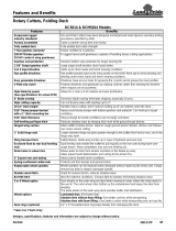
Section 7: Features and Benefits . . . . . .37
Section 8: Troubleshooting . . . . . . . . . . .39
Section 9: Appendix . . . . . . . . . . . . . . . . .40
Tire Inflation Chart . . . . . . . . . . . . . . . . . . . . . . . .40
Warranty . . . . . . . . . . . . . . . . . . . . . . . . . . . . . . .41

1
Important Safety Information
2/02/09
RC5020 (540 RPM) and RCM5020 (1000 RPM) Rotary Cutters 318-474M
Land Pride
Table of Contents
Important Safety Information
These are common practices that may or may not be applicable to the products described in
this manual.
Safety at All Times
Thoroughly read and understand
the instructions given in this
manual before operation. Refer to
the “Safety Label” section, read
all instructions noted on them.
Do not allow anyone to operate
this equipment who has not fully
read and comprehended this
manual and who has not been
properly trained in the safe
operation of the equipment.
▲ Operator should be familiar with
all functions of the unit.
▲ Operate implement from the
driver’s seat only.
▲ Make sure all guards and shields
are in place and secured before
operating the implement.
▲ Do not leave tractor or implement
unattended with engine running.
▲ Dismounting from a moving
tractor could cause serious injury
or death.
▲ Do not allow anyone to stand
between the tractor and
implement while backing up to the
implement.
▲ Keep hands, feet, and clothing
away from power-driven parts.
▲ Wear snug fitting clothing to avoid
entanglement with moving parts.
▲ Watch out for wires, trees, etc.,
when raising implement. Make
sure all persons are clear of
working area.
▲ Turning tractor too tight may
cause implement to ride up on
wheels. This could result in injury
or equipment damage.
▲ Do not carry passengers on
implement at any time.
!
Look For The Safety Alert Symbol
The SAFETY ALERT SYMBOL indicates there is a
potential hazard to personal safety involved and extra
safety precaution must be taken. When you see this
symbol, be alert and carefully read the message that
follows it. In addition to design and configuration of
equipment, hazard control and accident prevention
are dependent upon the awareness, concern,
prudence and proper training of personnel involved in
the operation, transport, maintenance and storage of
equipment.
Be Aware of
Signal Words
A Signal word designates a degree or
level of hazard seriousness. The
signal words are:
Indicates an imminently hazardous
situation which, if not avoided, will
result in death or serious injury. This
signal word is limited to the most
extreme situations, typically for
machine components that, for
functional purposes, cannot be
guarded.
!
DANGER
Indicates a potentially hazardous
situation which, if not avoided, could
result in death or serious injury, and
includes hazards that are exposed
when guards are removed. It mayalso
be used to alert against unsafe
practices.
Indicates a potentially hazardous
situation which, if not avoided, may
result in minor or moderate injury. It
may also be used to alert against
unsafe practices.
!
WARNING
!
CAUTION
For Your Protection
▲ Thoroughly read and understand
the “SafetyLabel” section, read all
instructions noted on them.
Shutdown and Storage
▲ Lower machine to ground, put
tractor in park, turn off engine, and
remove the key.
▲ Detach and store implements in a
area where children normally do
not play. Secure implement by
using blocks and supports.
OFF
REMO
VE

2
Important Safety Information
RC5020 (540 RPM) and RCM5020 (1000 RPM) Rotary Cutters 318-474M 2/02/09
Land Pride
Table of Contents
Transport
Machinery Safely
▲ Comply with state and local laws.
▲ Maximum transport speed for
implement is 20 mph. DO NOT
EXCEED. Never travel at a speed
which does not allow adequate
control of steering and stopping.
Some rough terrain require a
slower speed.
▲ Sudden braking can cause a
towed load to swerve and upset.
Reduce speed if towed load is not
equipped with brakes.
▲ Use the following maximum
speed - tow load weight ratios as
a guideline:
20 mph when weight is less
than or equal to the weight of
tractor.
10 mph when weight is double
the weight of tractor.
IMPORTANT: Do not tow a load that
is more than double the weight of
tractor.
Use Safety
Lights and Devices
▲ Slow moving tractors, self-
propelled equipment, and towed
implements can create a hazard
when drivenon public roads. They
are difficult to see, especially at
night.
▲ Flashing warning lights and turn
signals are recommended
whenever driving on public roads.
Use lights and devices provided
with implement.
Practice Safe Maintenance
▲ Understand procedure before
doing work. Use proper tools and
equipment, refer to Operator’s
Manual for additional information.
▲ Work in a clean dry area.
▲ Lower the implement to the
ground, put tractor in park, turn off
engine, and remove key before
performing maintenance.
▲ Allow implement to cool
completely.
▲ Do not grease or oil implement
while it is in operation.
▲ Inspect all parts. Make sure parts
are in good condition & installed
properly.
▲ Remove buildup of grease, oil or
debris.
▲ Remove all tools and unused
parts from implement before
operation.
Use A Safety Chain
▲ A safety chain will help control
drawn machinery should it
separate from the tractor
drawbar.
▲ Use a chain with the strength
rating equal to or greater than
the gross weight of the towed
machinery.
▲ Attach the chain to the tractor
drawbar support or other
specified anchor location. Allow
only enough slackin the chain to
permit turning.
▲ Do not use safety chain for
towing.
These are common practices that may or may not be applicable to the products described in
this manual.

3
Important Safety Information
2/02/09
RC5020 (540 RPM) and RCM5020 (1000 RPM) Rotary Cutters 318-474M
Land Pride
Table of Contents
Prepare for Emergencies
▲ Be prepared if a fire starts.
▲ Keep a first aid kit and fire
extinguisher handy.
▲ Keep emergency numbers for
doctor, ambulance, hospital and
fire department near phone.
911
Wear
Protective Equipment
▲ Protectiveclothingand equipment
should be worn.
▲ Wear clothing and equipment
appropriate for the job. Avoid
loose fitting clothing.
▲ Prolonged exposure to loud noise
can cause hearing impairment or
hearing loss. Wear suitable
hearing protection such as
earmuffs or earplugs.
▲ Operating equipment safely
requires the full attention of the
operator. Avoid wearing radio
headphones while operating
machinery.
These are common practices that may or may not be applicable to the products described in
this manual.
Keep Riders
Off Machinery
▲ Riders obstruct the operator’s
view. Riders could be struck by
foreign objects or thrown from the
machine.
▲ Never allow children to operate
equipment.
Tire Safety
▲ Tire changing can be dangerous
and should be preformed by
trained personnel using the
correct tools and equipment.
▲ When inflating tires, use a clip-on
chuck and extension hose long
enough to allow you to stand to
one side and NOT in front of or
over the tire assembly. Use a
safety cage if available.
▲ When removing and installing
wheels, use wheel handling
equipment adequate for the
weight involved.
Avoid High
Pressure Fluids Hazard
▲ Escaping fluid underpressure can
penetratetheskin causing serious
injury.
▲ Avoid the hazard by relieving
pressure before disconnecting
hydraulic lines or performing work
on the system.
▲ Make sure all hydraulic fluid
connections are tight and all
hydraulic hoses and lines are in
good condition before applying
pressure to the system.
▲ Use a piece of paper or
cardboard, NOT BODY PARTS, to
check for suspected leaks.
▲ Wear protective gloves and safety
glasses or goggles when working
with hydraulic systems.
▲ If an accident occurs, see a
doctor immediately. Any fluid
injected into the skin must be
treated within a few hours or
gangrene may result.

4
Important Safety Information
RC5020 (540 RPM) and RCM5020 (1000 RPM) Rotary Cutters 318-474M 2/02/09
Land Pride
Table of Contents
23595
818-045C
Pinch Point
Warning
27523
818-130C
Caution! Use
540 rpm PTO
only
818-240C
Caution! Use
1000 rpm PTO
only
Safety Labels
Your cutter comes equipped with all safety labels in place. They
were designed to help you safely operate your implement. Read
and follow their directions.
1. Keep all safety labels clean and legible.
2. Replace all damaged or missing labels. To order new
labels go to your nearest Land Pride dealer.
3. Some new equipment installed during repair requires
safety labels to be affixed to the replaced component as
specified by Land Pride. When ordering new components
make sure the correct safety labels are included in the
request.
4. Refer to this section for proper label placement.
To install new labels:
a. Clean the area the label is to be placed.
b. Spray soapy water on the surface where the label is to
be placed.
c. Peel backing from label. Press firmly onto the surface.
d. Squeeze out air bubbles with the edge of a credit card.


7
Important Safety Information
2/02/09
RC5020 (540 RPM) and RCM5020 (1000 RPM) Rotary Cutters 318-474M
Land Pride
Table of Contents
27523
27523
27523
27523
818-276C
Warning!RotatingBlade
Hazard
TRACTOR MUST HAVE SAFETY GUARDING
818-840C
Danger: Rollover Hazard
818-561C
Warning! Moving
Parts Hazard
Located on
Left Wing &
Right Wing
818-830C
Safety Combo
Located on
Left Wing &
Right Wing

8
Important Safety Information
RC5020 (540 RPM) and RCM5020 (1000 RPM) Rotary Cutters 318-474M 2/02/09
Land Pride
Table of Contents
838-588C
Warning: Folding Cutter Speed Warning
838-094C
Warning: High Pressure
23594
23594
23594
23594
818-556C
Danger! Thrown
Object Hazard
Located on Left Wing
& Right Wing
818-564C
Danger!
Rotating Blade
Located on Left Wing
& Right Wing


10
Introduction
RC5020 (540 RPM) and RCM5020 (1000 RPM) Rotary Cutters 318-474M 2/02/09
Land Pride
Table of Contents
Introduction
Owner Assistance
The Warranty Registration card should be filled out by
the dealer at the time of purchase. This information is
necessary to provide you with quality customer service.
If customer service or repair parts are required contact a
LandPride dealer. Adealerhastrainedpersonnel, repair
parts and equipment needed to service the cutter.
The parts on your cutter have been specially designed
and should only be replaced with genuine Land Pride
parts. Therefore, should your cutter require replacement
parts go to your Land Pride Dealer.
Serial Number Plate
Refer to the Figure 1 for the location of your serial
number plate. For prompt service always use the serial
number and model number when ordering parts from
your Land Pride dealer. Be sure to include your serial
and model numbers in correspondence also.
Serial Number Plate Location
Figure 1
Free Maintenance Video
Be sure to request your free copy of the 15’ Rotary
Cutter Maintenance Guidelines (also applicableto 10’,
14’& 20’ cutters)video from yourlocal Land Pride dealer.
Further Assistance
Your dealer wants you to be satisfied with your new
machine. If for any reason you do not understand any
part of this manual or are not satisfied with the service
received, the following actions are suggested:
1. Discuss the matter with your dealership service
manager making sure he is aware of any problems
youmayhaveand that he has had the opportunity to
assist you.
2. If you are still not satisfied, seek out the owner or
general manager of the dealership, explain the
problem and request assistance.
3. For further assistance write to:
Land Pride Service Department
1525 East North Street
P.O. Box 5060
Salina, Ks. 67402-5060
E-mail address
lpser[email protected]
27524
Land Pride welcomes you to the growing family of new
product owners.
Thisimplement has been designedwith care and builtby
skilledworkersusingqualitymaterials.Properassembly,
maintenance, and safe operating practices will help you
get years of satisfactory use from this machine.
The parts on your Rotary Cutter have been specially
designedandshouldonlybe replacedwithgenuineLand
Prideparts. Therefore, should your Rotary Cutter require
replacement parts go to your Land Pride Dealer.
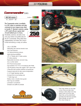
Application
The heavy duty RC5020 and RCM5020 Series Rotary
Cutters are designed and built by Land Pride to provide
excellent cutting performance on gently sloping or
slightlycontoured right ofways, roadsides,pastures, set-
aside-acres, or for residue in row crop fields.
The 20’ cutting width, 2" to 14" cutting height and ability
to cut weeds and brush up to 3" in diameter make them
well suited for these applications.
Bothmodelsofferpull-typeself-levelingclevishitchesfor
attachment to 70-250 hp tractors. The RC5020 has a
Cat. 5 and 540 rpm driveline, while the RCM5020 has a
Cat. 5 and 1000 rpm driveline.
Both models offer various safety guard selections
making them an excellent choice for state and municipal
mowing applications. See “Features and Benefits”
section 6 or “Product Specifications” section 5 for more
information and performance enhancing options.
Using This Manual
•
This Operator’s Manual is designed to help familiarize
you with safety, assembly, operation, adjustments,
troubleshooting, and maintenance. Read this manual
and follow the recommendations to help ensure safe
and efficient operation.
• The information contained within this manual was
current at the time of printing. Some parts may change
slightly to assure you of the best performance.
• To orderanew Operator’s orPartsManual contact your
authorized dealer. Manuals can also be downloaded,
free-of-charge from our website at www.landpride.com.
Terminology
“Right” or “Left” as used in this manual is determined by
facing forward in the direction the machine will operate
while in use unless otherwise stated.
Definitions
IMPORTANT: A special point of information related
to its preceding topic. Land Pride’s intention is that
this information should be read and noted before
continuing.
NOTE: A special point of information that the
operator must be aware of before continuing.

11
Section 1: Assembly and Set-up
2/02/09
RC5020 (540 RPM) and RCM5020 (1000 RPM) Rotary Cutters 318-474M
Land Pride
Table of Contents
Section 1: Assembly and Set-up
Tractor Requirements
Horsepower
Tractor horsepower should be within the range noted
below. Tractors outside the horsepower range must not
be used.
Horsepower Rating. . . . . . . . . . . . . . . . . . 70-250 HP
Hitch
Refer to Figure 1-1:
Maintainproperdistance,dimension“A”,betweencenter
of drawbar hitch pin hole and end of tractor PTO shaft.
Hitch Type. . . . . . . . . . . . . . . . . . . . . . . . . . Draw Bar
540 RPM Rear PTO Speed:
“A” . . . . . . . . . . . . . . . . . . . . . . . . . . . . . . . . . . . 14"
“B” . . . . . . . . . . . . . . . . . . . . . . . . . . . . . . . . . . . . 8"
“C” . . . . . . . . . . . . . . . . . . . . . . . . . . . . . . 18" to 21"
1000 RPM Rear PTO Speed:
“A” . . . . . . . . . . . . . . . . . . . . . . . . . . . . . . . . . . . 16"
“B” . . . . . . . . . . . . . . . . . . . . . . . . . . . . . . . . . . . . 8"
“C” . . . . . . . . . . . . . . . . . . . . . . . . . . . . . . 18" to 21"
PTO to Drawbar Distance
Figure 1-1
Hydraulic Outlets
The number of tractor hydraulic duplex outlets is
dependent upon how the Rotary Cutter is set-up.
• Two duplex outlets are required if the wings are raised
and lowered simultaneously.
• Three duplexoutletsare required ifthewings are raised
and lowered independently.
Control valve kits are available from your local Land
Pride dealer if the tractoris not equipped withthe correct
number of duplex outlets. See “Hydraulic Accessories”
on page 23 for available hydraulic kits.
IMPORTANT: PTO damage may occur if distance
“A” is not properly maintained.
22273
PTO Speed
!
CAUTION!
Do not over speed PTO. The cutter can be damaged when
operated above its rated PTO RPM.
Rear PTO Speed:
Model RC5020. . . . . . . . . . . . . . . . . . . . . 540 RPM
Model RCM5020 . . . . . . . . . . . . . . . . . . 1000 RPM
Before You Start
Read and understand the operator’s manual for your
cutter. An understanding of how it works will aid in the
assembly and setup of your cutter.
It is best to go through the Pre-Assembly Checklist
before assembling the cutter. Speed up your assembly
task and make the job safer by having all needed parts
and equipment readily at hand.
Torque Requirements
Refer to “Torque Values Chart” on page 40 to determine
correct torque values when tightening hardware.
Pre-Assembly Checklist
Check Reference
Have a fork lift or loader with properly sized chains and safety
stands capable of lifting and supporting the equipment on hand.
Have a minimum of two people available during assembly.
Make sure all major components and loose
parts are shipped with the machine.
Operator’s
Manual
Double check to make sure all parts, fasteners
and pins are installed in the correct location.
Refer to the Parts Manual if unsure. By double
checking, you will lessen the chance of using a
bolt incorrectly that may be needed later.
NOTE: All assembled hardware from the factory
has been installed in the correct location.
Remember location of a part or fastener if
removed during assembly. Keep parts
separated.
Operator’s
Manual
330-323M
Parts Manual
330-323P
Make sure working parts move freely, bolts are
tight & cotter pins are spread.
Operator’s
Manual
Make sure all grease fittings are in place and
lubricated.
Page 30
Make sure all safety labels are correctly located
and legible. Replace if damaged.
Page 4
Make sure all red and amber reflectors are
correctly located and visible when machine is in
transport position.
Page 9
Make sure all tires are inflated to the specified
psi air pressure and all wheel bolts and axle
nuts are tightened to the specified torque.
Page 40
IMPORTANT: Do not attempt to operate a 540 RPM
driveline with a 1,000 RPM PTO tractor or a 1,000
RPM driveline with a 540 RPM PTO tractor. Many
tractors provide both 540 and 1,000 RPM PTO
modes.Checkyourtractor’s manualto determine its
capabilities.

12
Section 1: Assembly and Set-up
RC5020 (540 RPM) and RCM5020 (1000 RPM) Rotary Cutters 318-474M 2/02/09
Land Pride
Table of Contents
Hitch Types
Thecutterisfactorysuppliedwithastandardclevishitch.
The optional pintle hitch is also available. See your
nearest Land Pride dealer should you want to change
your hitch set-up.
Standard Clevis Hitch
Refer to Figure 1-2:
A level rod attached to the underside of the clevis keeps
the clevis parallel with the tractor drawbar at all cutting
heights. Cutter rotation about the tractor drawbar is
limited to slots located in the clevis’ upper and lower
plates.Hitchshould be secured to the tractor tongue with
bolt, washers and nuts to prevent spreading of clevis.
Pintle Hitch (Optional)
Refer to Figure 1-3:
A pintle leveling rod attached to the underside of the
pintle keeps the pintle parallel with the tractor drawbar at
all cutting heights. Cutter rotation about the tractor
drawbar is limited to movement about the pintle
connection.
Hitch Assembly
Refer to Figure 1-4:
1. Install clevis rod (#1) to the deck center lug using
3/4” x 1 1/2” clevis pin (#6), 3/4” flat washer (#4) and
5/32” x 1 1/4” cotter pin (#5).
2. Install left and right leveling rods (#2) to hitch frame
(#3) with 3/4” x 1 1/2” clevis pins (#6), 3/4” flat
washes (#4) and 5/32” x 1 1/4” cotter pins (#5). Final
adjustment should be made when the cutter is
attached to the tractor.
3. Install parking jack (#7) to hitch frame (#1) and
secure with attached pin (#8). Adjust parking jack to
preferred drawbar height.
Wing Axle Assembly
Refer to Figure 1-5:
!
WARNING!
Connect turnbuckle #4 between wing axle flanges before
lowering wing. Otherwise, personal injury and/or damage to
turnbuckle can occur.
Wing axles are secured folded backing for shipping
purposes.
1. Remove ties securing left and right wing axles (#1)
and rotate axles to install turnbuckles (#4).
2. Remove locknuts (#3) and cap screws (#2).
3. Attach left and right turnbuckles (#4) to wing axles
with existing 1”-8 Gr8 cap screws (#2) and 1” lock
nuts (#3). Make sure grease zerks are facing up
when wings are folded down.
4. Tighten locknuts (#3) to the correct torque.
NOTE: Do not tighten hardware until wing axle
assembly is complete.
Standard Clevis Hitch
Figure 1-2
Pintle Hitch
Figure 1-3
Hitch Assembly Illustration
Figure 1-4
Wing Axle - Turnbuckle Assembly
Figure 1-5
22268
24730
24847
15336
Turnbuckle (#3)
to be secured
between the two
flanges.

13
Section 1: Assembly and Set-up
2/02/09
RC5020 (540 RPM) and RCM5020 (1000 RPM) Rotary Cutters 318-474M
Land Pride
Table of Contents
Tractor Hook-up
!
DANGER!
Crushing Hazard between tractor and implement. Do notallow
anyone to stand between the tractor and implement while
backing-up to an implement. Never operate the hydraulic
3-point lift controlswhile someone is directlybehind the tractor.
Refer to Figure 1-6:
Tractor Hookup to Standard Clevis Hitch
Figure 1-6
1. Make certain the parking jack (#3) is properly
attached to the cutter hitch and secured with
attachment pin (#8).
2. Back tractor within close proximity of cutter
clevis (#11).
3. Raise or lower the parking jack (#3) to align clevis
(#11) with the tractor drawbar. Drawbar should fit
between lower and upper plates of clevis.
4. Back tractor up to cutter hitch until holes in the
drawbar and clevis (#11) are aligned.
5. Insert 1" flat washers (#9) equally above and below
tractor drawbar until both spaces between drawbar
and clevis plates are filled.
IMPORTANT: Jack attachment pin (#8) must be fully
inserted and secured before working on or around a
cutter that is not hooked to the tractor drawbar.
NOTE: Items 1, 2, 9 and 10 shown in Figure 1-6 are
not furnished by Land Pride.
23590
6. Insert 1" x 5" gr5 hex bolt (#1) through top of clevis
(#11), 1" washers (#9), drawbar, remaining 1"
washers (#9) and out through bottom of clevis(#11).
Secure hex bolt with nut (#2). Tighten nut snugly to
remove all play and then back nut one-quarter turn.
Tighten jamb nut (#10) against nut (#2).
7. Lower jack stand (#3) until hitch weight is removed.
Remove jack stand from hitch and store on left hand
deck wing storage base. Prevent water and freeze
damage by storing it so that the foot is level or lower
than the head, especially when the wing is folded up.
8. Attach hitch safety chain (#4) to the tractor. Adjust
chain length to remove all slack except what is
necessary to permit turning. Lock chain hook
securely to the safety chain.
Driveline Installation
!
DANGER!
Do not engage tractor PTO while hooking-up and unhooking
the driveline or stand near a rotating driveline. A person’sbody
and/or clothing can become entangled in the driveline resulting
in serious injury or death.
!
CAUTION!
Always disengage PTO, engage parking brake, shut tractor
engine off, remove switch key and wait for blades to come a
complete stop before dismounting from tractor.
The main driveline may be either constant velocity type
or conventional type. Pull-collar couplers and retaining
bolts are used to connect the driveline to the tractor and
implement gearbox.
A driveline that is too long can damage the tractor,
gearbox and/or driveline. Always check driveline length
with cutter hitched to the tractor before engaging the
PTO.
IMPORTANT: The driveline must be lubricated
before putting it into service. Refer to “Lubrication
Points” on page 30.
IMPORTANT: Do not attempttooperatea 540 RPM
driveline at 1,000 RPM or a 1,000 RPM driveline at
540RPM. Manytractors provideboth 540 and1,000
RPM PTO speeds. Check your tractor’s manual to
determine its capabilities.
IMPORTANT: Read and understand “Section 3:
OperatingInstructions”beginning onpage17before
operating the Rotary Cutter.

14
Section 1: Assembly and Set-up
RC5020 (540 RPM) and RCM5020 (1000 RPM) Rotary Cutters 318-474M 2/02/09
Land Pride
Table of Contents
Check Driveline Length
Refer to Figure 1-4 on page 12:
1. Park tractor and cutter in a straight line on a level
surface. Place gear selector in park, shut tractor
engine off, set park brake and remove switch key.
2. Remove protective shaft sleeve (#9) from input shaft
of splitter gearbox.
3. Attach bolted coupler of driveline (#10) to divider
gearbox shaft and pull-collar coupler to tractor PTO
shaft. Skip to step 5 if driveline fits between tractor
and implement.
Refer to Figure 1-7:
4. The PTO driveline will require shortening if it does
not fit between tractor and cutter gearbox. Shorten
driveline as follows:
a. Pull driveline apart as shown in Figure 1-7.
b. Attach pull-collar coupler to the tractor PTO shaft
and bolted coupler to the divider gearbox shaft.
Pull on each driveline section to be sure the
universal joints are secured to the shafts.
c. Hold driveline sections parallel to each other to
determineiftheyaretoolong.Theinnerand outer
shieldsoneachsectionshouldendapproximately
1" short of reaching the universal joint shield on
the adjacent section (see “B” dimension). If they
are too long, measure 1" (“B” dimension) back
fromuniversaljointshieldandmakeamarkat this
location on the inner and outer driveline shields.
d. Cut off inner shield at the mark (“X” dimension).
Cut the same amount off the inner shaft (“X1”
dimension). Repeat cut off procedure (“Y”&“Y1”
dimensions) to the outer driveline half.
e. Remove all burrs and cuttings.
f. Apply multi-purpose grease to the inside of the
outer shaft and reassemble driveline.
g. Attach inner driveline yoke end to the divider
gearbox shaft.
h. Attach outer driveline yoke end to the tractor's
shaft.
5. Thedrivelineshould nowbe movedbackand forthto
insurebothendsare securedtothetractorandcutter
PTO shafts. Reattach any end that is loose.
IMPORTANT: The Rotary Cutter must be hitched to
thetractorwithtractorand cutter aligned inastraight
lineon a levelsurface.This arrangement will provide
thecorrect alignmentbetweentractorPTOshaftand
gearbox input shaft.
IMPORTANT: Two or three small chains are
supplied with each driveline. These chains must be
attached to outer and inner driveline shields and to
cutter and tractor to restrict driveline shields from
rotating. If driveline has 3 chains, all 3 chains must
be secured to keep driveline shields from rotating.
PTO Driveline Shortening
Figure 1-7
6. Refer to Figure 1-6 on page 13. Secure chains (#6)
on driveline (#5) around hitch clevis rod to restrict
driveline outer shield from rotating. Re-latch safety
chain to driveline guard.
7. Attach safety chain located on the other end of the
driveline (#5) to the cutter’s main frame to restrict
driveline inner shield from rotating. Re-latch safety
chain to driveline guard.
Hydraulic Hook-up
The required number of duplex outlets at the tractor is
dependent upon how the cutter is set-up.
The standard cutter is equipped with three hydraulic
cylinders with one in the center for lifting the cutter and
one on each wing for folding the wings simultaneously.
All three cylinders are set-up for single action
(one-way) operation.
Each duplex outlet on your tractor can perform only one
operation. One outlet is needed for lifting the cutter and
one for lifting the wings simultaneously. A third outlet is
required if the wings are lifted independently. This will
also require replumbing the wing hydraulic cylinders.
Your Land Pride dealer can help you determine the best
configuration that will match your needs and your tractor
capabilities.Optionalcontrolvalvekitsareavailableifthe
tractor does not have the required number of duplex
outlets. For additional information, See Hydraulic
Accessories on page 23.
!
DANGER!
Hydraulic fluid under pressure can penetrate skin. Wear
protective gloves and safety glasses or goggles when working
with hydraulic systems. Use a piece of cardboard or wood
rather than hands when searching for hydraulic leaks. If
hydraulic fluid is injected into the skin, it must be treated by a
doctor within a few hours or gangrene may result.
22165

15
Section 1: Assembly and Set-up
2/02/09
RC5020 (540 RPM) and RCM5020 (1000 RPM) Rotary Cutters 318-474M
Land Pride
Table of Contents
!
WARNING!
Be surecenterdeckand wings areloweredto the groundand all
hydraulic pressure is relieved before disconnecting any
hydrauliclinesor fittings between the Rotary Cutter and tractor
hydraulic system.
Refer to Figure 1-6 on page 13:
1. Route cylinder hoses (#7) through hose support loop
and connect to tractor remote outlets.
2. Cycle hydraulicsystem byraisingand lowering center
deck cylinder and wing fold cylinders. It may be
necessarytopurgethehydraulicsystemoftrappedair
if operation is sluggish.
The system may be purged as follows:
a. With wings lowered to the ground and hydraulic
pressure relieved, loosen hydraulic hose fitting at
each wing cylinder slightly to allow fluid to escape.
b. Slowly activate tractor control valve to purge any
trapped air from the system.
c. Tighten each fitting.
3. The center deck lift cylinder is purged in the same
manner as the wing cylinders. The cutter must be
resting on the ground and all hydraulic pressure
relievedbeforelooseninghosefittingasdescribed in
2a above.
4. Check driveline for adequate clearance under all
ranges of cutter height. With driveline shaft attached
to the tractor, slowly raise and lower the cutter to its
upper and lower limits while observing clearances
between hitch and driveline. Adjust tractor drawbar
height and/or length if driveline interferes. See
Figure 1-1 on page 11 for correct drawbar
dimensions.
Unhooking From the Cutter
1. Parkcutteronalevelsolidhardsurface.Placetractor
gear selector in park and set park brake.
Refer to Figure 3-1 & Figure 3-2 on page 18:
2. Raise wings up in the transport position and place
transport lock bars in the locked position. Make sure
transport bars are secured in place with lock
pins (#2) and hairpin cotters (#1).
Refer to Figure 2-2 on page 16:
3. Remove stroke control spacers from the center
hydraulic cylinder and lower cutter until front skids
are resting on the ground. Replace stroke control
spacers as needed to support wheels at this
position.
4. With tractor gearselector in parkand park brakeset,
shut tractor engine off, and removeswitchkey. Move
cylinder lift leversback and forth to release hydraulic
line pressure.
Refer to Figure 1-6 on page 13:
5. Removejackstand (#3) from the left hand wing deck
and attach to cutter hitch. Secure jack stand in place
with attached jack pin (#8).
6. Unhook hydraulic hoses (#7), driveline safety
chains (#6), driveline(#5) andhitch safetychain (#4)
from the tractor. Store hose ends in hose support
loop.
7. Adjustjackstandupordownas needtoremovehitch
pin (#1).
8. Drivetractorawayfromthecutterandthenlowerjack
stand to rest cutter on its front skid shoes.

16
Section 2: Adjustments
RC5020 (540 RPM) and RCM5020 (1000 RPM) Rotary Cutters 318-474M 2/02/09
Land Pride
Table of Contents
Center and Wing Section Leveling
These adjustments should be made with your cutter
hooked up to the same tractor that will be used for field
operations or one having the same drawbar height.
Adjust leveling rods as described below.
Refer to Figure 2-1 & Figure 2-2:
1. Attach cutter to tractor and position it on level ground.
2. Raise both wings to locked position.
3. Using hydraulic lift, adjust center deck height so that
the front skids (#2) are 2 to 3 inches above ground.
4. Measurerightandlefthandsidesofthecentersection
from ground line to center line of hinge rods (#1). The
hinge rods should be 1” closer to the ground at the
front than they are at the back. If they are not, loosen
bothjamnuts(#3)androtateadjustingnuts(#4)atthe
same time until the right and left hand sides are
inclined from front to back by 1”.
5. Be sure that both sides are equal distance from
groundlineto center lineof hinge rodand that left and
right leveling rods have equal tension. Re-tighten jam
nut (#3).
NOTE: Lengthening leveling rods with adjusting
nuts (#4) will lower the front of the cutter.
6. Lower wings to ground position. Wing sections will
need adjusting if wing top deck sheets are not level
with center top deck sheet. Level right side by
loosening jam nut (#5) and rotating adjusting
turnbuckle (#6) until right wing is level with center
section. Re-tighten jam nut (#5).Repeat procedureto
level left wing deck.
Front Skid Position
Figure 2-1
Cutting Height Adjustment
Refer to Figure 2-2:
Stroke control spacers are supplied to accommodate
various cutting heights. Remove or add control spacers
to the cylinder rod by spreading them apart at the break
line. Removing spacers lowers the deck and adding
spacers raises the deck.
Front Skid
23574
Section 2: Adjustments
Center Section Leveling Rod
Figure 2-2
Jam
3
4
22152
5
6
1
Right Hand
Leveling Rod
Left Hand
Leveling Rod
StrokeControl
Spacers
Jam
3
4

17
Section 3: Operating Instructions
2/02/09
RC5020 (540 RPM) and RCM5020 (1000 RPM) Rotary Cutters 318-474M
Land Pride
Table of Contents
Pre-Start Checklist
Hazard control and accident prevention are dependent
upon the awareness, concern, prudence and proper
traininginvolvedintheoperation,transport,maintenance
and storage of the Rotary Cutter. Therefore, it is
absolutely essential that no one operates the cutter
without first having read, fully understood and become
totallyfamiliarwiththeOperator’sManual.Makesurethe
operator has completed the Operating Checklist below.
Inspection Procedures
!
DANGER!
Do not engage tractor PTO while hooking-up and unhooking
the driveline or stand near a rotating driveline. A person’sbody
and/or clothing can become entangled in the driveline resulting
in serious injury or death.
!
CAUTION!
Always disengage PTO, engage parking brake, shut tractor
engine off, remove switch key and wait for blades to come a
complete stop before dismounting from tractor.
1. Make sure tractor PTO is disengaged and cutter
blades have come to a complete stop.
2. Park tractor and cutter on a level surface.
3. Raise and lock wings in the folded-up position with
transport locks. See “Transport Locks” on page 18.
4. Raise center deck fully up and place sturdy support
blocks or jack stands under the four deck corners.
Lower center deck down onto the supports.
Operating Checklist
✔ Check
Page No.
Read and follow all Safety Rules & Safety Decals
carefully. Refer to “Important Safety Information”.
Page 1
Make sure all guards and shields are in place.
Refer to “Important Safety Information”.
Page 1
Read and follow Hook-up & preparation instructions.
Refer to “Section 1: Assembly and Set-up”. Page 11
Read and follow all operating procedures.
Refer to “Section 3: Operating Instructions”.
Page 17
Read and make all required adjustments.
Refer to “Section 2: Adjustments”. Page 16
Read and follow all Maintenance Instructions.
Refer to “Section 5: Maintenance & Lubrication”. Page 24
Read and follow all Lubrication Instructions.
Refer to “Lubrication Points”.
Page 30
Make sure all gearboxes are properly lubricated.
Refer to Gearbox lubrication. Page 31
Check cutter initially and periodically for loose bolts
and pins. Refer to “Torque Values Chart”. Page 40
5. Place tractorgear selector in park, shut tractor engine
off, remove switch key and dismount from tractor.
6. Check cutting blades for sharpness. Refer to “Cutter
Blade Maintenance” on page 24.
7. Inspect tractor safety equipment to make sure it is in
good working condition.
8. After completing inspection and making any
necessary repairs, remove supports from under the
deck and wing transport locks. Lower wings level
with center deck and then lower Rotary Cutter down
to about 2" off the ground.
The remaining inspections are made by engaging the
PTO to check for normal operation.
!
CAUTION!
Tractor PTO shield and all Rotary Cutter guards must be in
place at all times during operation!
9. Start tractor, set throttle to idle or slightly above idle
and slowly engage PTO. Initial start-up vibration is
normal and should stop after a few revolutions. Stop
PTO rotation immediately if vibration continues.
10. Once cutter is running smoothly, increase tractor
PTO speed to the appropriate rpm. Stop PTO
rotation immediately if vibration occurs.
11. Investigate the cause of vibration if it does occur.
Make sure cutter blades are not locked against each
other. See “Field Set-up” on page 19.
IMPORTANT: Stop PTO immediately if vibration
continues after a few revolutions during start-up and
anytimeit occurs thereafter.WaitforPTOto cometo
a complete stop before dismounting from tractor to
check for probable causes. Make necessary repairs
and adjustments before continuing on.
IMPORTANT: Do not exceed the cutter’s rated PTO
speed. Excessive engine speed will damage the
power train components.
Section 3: Operating Instructions

18
Section 3: Operating Instructions
RC5020 (540 RPM) and RCM5020 (1000 RPM) Rotary Cutters 318-474M 2/02/09
Land Pride
Table of Contents
Transport Locks
Cutter wings willneed tobe raised before transporting on a
roadway, through narrow gate openings and when
servicing the deck underside.
Refer to Figure 3-1 & Figure 3-2:
1. Disengage tractor PTO and wait for the cutter
bladesto come to a complete stop before raising the
wings.
2. Raise the cutter wings fully up with the hydraulics.
3. Place tractor gear selector in park, shut tractor
engine off, set park brake, remove switch key and
dismount from tractor.
4. See Figure 3-2. Remove hairpin cotter (#1) from
storage pin (#2).
5. Rotate end of transport lock bar (#3) to cylinder
pin (#4) as shown in Figure 3-1. Secure with hairpin
cotter (#1).
6. Repeat steps 4 and 5 for the other wing section.
Cutter is now ready for transporting.
Transporting
!
CAUTION!
When traveling on public roads at night or during the day, use
accessory lights and devices for adequate warning to operators
of other vehicles. Comply with all federal, state and local laws.
1. Select a safe ground speed when transporting from
one area to another.
2. Besure to reduce tractor groundspeedwhenturning
and leave enough clearance so the cutter does not
contact obstacles such as buildings, trees or fences.
3. Always raise wings and set transport locks to keep
wing decks from falling before traveling on public
roadways.
4. Whentravelingon roadways,transportinsuch a way
that faster moving vehicles may pass you safely.
5. Shift tractor to a lower gear when traveling over
rough or hilly terrain.
IMPORTANT: Always disengage tractor’s PTO and
wait for blades to stop before raising cutter wings to
transport position. Drivelines and gearboxes will be
damaged if cutter wings are raised while PTO is
turning.
NOTE:Thewingsarecontrolled with two hydraulic lift
cylinders. Be certain that the wing hydraulics are
attachedtothetractorand thehydraulichoses arefull
of oil before proceeding.
Transport Bar, Locked Position
Figure 3-1
Transport Bar, Storage Position
Figure 3-2
1
23592
4
3
23593
1
3
2
Page is loading ...
Page is loading ...
Page is loading ...
Page is loading ...
Page is loading ...
Page is loading ...
Page is loading ...
Page is loading ...
Page is loading ...
Page is loading ...
Page is loading ...
Page is loading ...
Page is loading ...
Page is loading ...
Page is loading ...
Page is loading ...
Page is loading ...
Page is loading ...
Page is loading ...
Page is loading ...
Page is loading ...
Page is loading ...
Page is loading ...
Page is loading ...
/