Furuno SC 50 User manual
- Category
- Navigational compasses
- Type
- User manual
This manual is also suitable for

T
HD
S
A
TELLITE
C
O
M
P
A
SS
S
C
-
110

Your Local Agent/DealerYour Local Agent/Dealer
9-52 Ashihara-cho,9-52 Ashihara-cho,
Nishinomi
y
a, Ja
p
anNishinomi
y
a, Ja
p
an
Tele
p
hone :Tele
p
hone : 0798-65-21110798-65-2111
faxfax 0798-65-42000798-65-4200
::
F
IRST EDITION :
F
IRST EDITION : FEBFEB .. 20042004
Printed in JapanPrinted in Japan
A
ll ri
g
hts reserved.
A
ll ri
g
hts reserved.
A2A2 :: JUNJUN .. 30, 200430, 2004
PUB.No.PUB.No. OME-72570OME-72570
*
00014854600
*
*
00014854600
*
*
00014854600
*
*
00014854600
*
(( DAMIDAMI ))
SC-110SC-110
* 0 0 0 1 4 8 5 4 6 0 0 ** 0 0 0 1 4 8 5 4 6 0 0 *
*
OME
72570
A
20
*
*
OME
72570
A
20
*
*
OME
72570
A
20
*
*
OME
72570
A
20
*
* O M E 7 2 5 7 0 A 2 0 ** O M E 7 2 5 7 0 A 2 0 *

i
SAFETY INSTRUCTIONS
WARNING
Do not disassemble or modify the
equipment.
Fire, electrical shock or serious injury can
result.
Immediately turn off the power at the
switchboard if the equipment is emitting
smoke or fire.
Continued use can cause fatal damage to
the equipment. Contact a FURUNO agent
for service.
Do not place liquid-filled containers on
the top of the processor unit.
Fire or electrical shock may result if the
liquid enters the equipment.
Use the proper fuse.
Use of a wrong fuse can damage the
equipment and cause fire.
CAUTION
No one navigation device should ever
be solely replied upon for the navigation
of a vessel.
Always confirm position against all avail-
able aids to navigation (incl. nautical charts),
for safety of vessel and crew.
Safety Instructions for the Operator Safety Instructions for the Installer
NOTICE
Observe the following compass safe
distances to prevent interference to a
magnetic compass:
Standard
Compass
Steering
Compass
Display unit
SC-502
0.4 m 0.3 m
Processor unit
SC-1101
0.9 m
0.6 m
Antenna unit
SC-1203F
0.3 m 0.3 m
ELECTRICAL SHOCK HAZARD
Do not open the equipment.
Only qualified personnel
should work inside the
equipment.
WARNING
Turn off the power at the switchboard
before beginning the installation.
Fire or electrical shock can result if the
power is left on.
Do not install the equipment where it
may get wet from rain or water splash.
Water in the equipment can cause fire,
electrical shock or damage to the equipment.
WARNING
To avoid electrical shock, do not
remove cover. No user-serviceable
parts inside.
WARNING LABEL
A warning label is attached to the
processor unit. Do not remove the label.
If the label is missing or damaged,
contact a FURUNO agent or dealer
about replacement.
WARNING LABEL
Name: Warning Label (1)
Type: 86-003-1011-1
Code No.: 100-236-231

ii
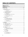
TABLE OF CONTENTS
TABLE OF CONTENTS ..................................................................................................ii
FOREWORD ..................................................................................................................iv
SYSTEM CONFIGURATION...........................................................................................v
EQUIPMENT LIST..........................................................................................................vi
SPECIFICATIONS.....................................................................................................SP-1
1 INSTALLATION...................................................................................................... 1-1
1.1 Mounting Considerations..................................................................................................... 1-1
1.1.1 Antenna unit............................................................................................................. 1-1
1.1.2 Display unit, processor unit...................................................................................... 1-3
1.2 Installing the Antenna Unit................................................................................................... 1-4
1.3 Installing the Processor Unit................................................................................................ 1-7
1.3.1 Bulkhead mount....................................................................................................... 1-7
1.3.2 Deck mount.............................................................................................................. 1-8
1.3.3 Installation on the underside of a desk .................................................................... 1-9
1.4 Installing the Display Unit .................................................................................................. 1-10
1.4.1 Desktop, overhead mounting................................................................................. 1-10
1.4.2 Flush mount ........................................................................................................... 1-10
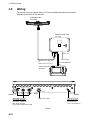
1.5 Wiring................................................................................................................................. 1-12
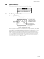
1.6 Initial Settings .................................................................................................................... 1-15
1.6.1 Confirming satellite status...................................................................................... 1-15
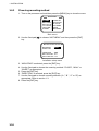
1.6.2 Choosing mounting method................................................................................... 1-16
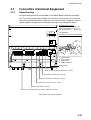
1.7 Connection of External Equipment.................................................................................... 1-17
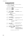
1.7.1 General wiring........................................................................................................ 1-17
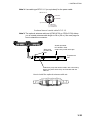
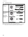
1.7.2 Fabrication of cables.............................................................................................. 1-18
2 OPERATION........................................................................................................... 2-1
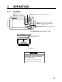
2.1 Controls................................................................................................................................ 2-1
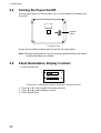
2.2 Turning the Power On/Off.................................................................................................... 2-2
2.3 Panel Illumination, Display Contrast.................................................................................... 2-2
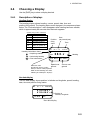
2.4 Choosing a Display..............................................................................................................2-3
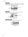
2.4.1 Description of displays............................................................................................. 2-3
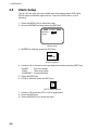
2.5 Alarm Setup ......................................................................................................................... 2-6
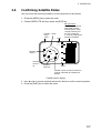
2.6 Confirming Satellite Status .................................................................................................. 2-7
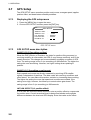
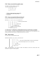
2.7 GPS Setup........................................................................................................................... 2-8
2.7.1 Displaying the GPS setup menu.............................................................................. 2-8
2.7.2 GPS SETUP menu description................................................................................ 2-8
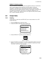
2.8 Output Data.......................................................................................................................... 2-9
2.8.1 Heading.................................................................................................................... 2-9
2.8.2 Log pulse ............................................................................................................... 2-13
2.9 System Setup ....................................................................................................................2-14
2.9.1 Geodetic data......................................................................................................... 2-14
2.9.2 Units of measurement............................................................................................ 2-15
2.9.3 Using local time...................................................................................................... 2-15

iii
2.9.4 Time format............................................................................................................ 2-15
2.9.5 Demonstration mode.............................................................................................. 2-16
2.10 WAAS/DGPS Setup........................................................................................................... 2-17
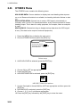
2.11 OTHERS Menu.................................................................................................................. 2-20
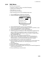
2.12 TRIP Menu......................................................................................................................... 2-21
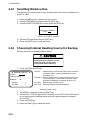
2.13 Resetting Distance Run..................................................................................................... 2-22
2.14 Choosing External Heading Source for Backup................................................................ 2-22
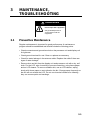
3 MAINTENANCE, TROUBLESHOOTING................................................................3-1
3.1 Preventive Maintenance ...................................................................................................... 3-1
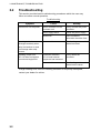
3.2 Troubleshooting ................................................................................................................... 3-2
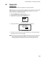
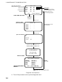
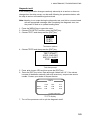
3.3 Diagnostics .......................................................................................................................... 3-3
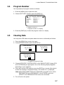
3.4 Program Number ................................................................................................................. 3-7
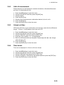
3.5 Clearing Data....................................................................................................................... 3-7
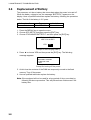
3.6 Replacement of Battery ....................................................................................................... 3-8
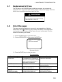
3.7 Replacement of Fuse........................................................................................................... 3-9
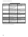
3.8 Error Messages ................................................................................................................... 3-9
APPENDIX................................................................................................................AP-1
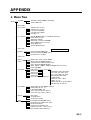
1. Menu Tree ............................................................................................................................. AP-1
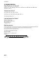
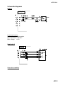
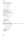
2. Digital Interface...................................................................................................................... AP-2
3. Input/Output Ports ................................................................................................................. AP-8
4. Parts List and Parts Location .............................................................................................. AP-10
5. Geodetic Chart Codes......................................................................................................... AP-12
6. Principle of Satellite Compass............................................................................................. AP-13
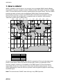
7. What is WAAS? ................................................................................................................... AP-14
PACKING LIST
OUTLINE DRAWINGS
INTECONNECTION DIAGRAM
INDEX.........................................................................................................................IN-1
Declaration of Conformity

i
v
FOREWORD
A Word to the Owner of the SC-110
FURUNO Electric Company thanks you for purchasing the FURUNO SC-110
THD Satellite Compass. (Hereafter, for sake of brevity, we refer to SC-110 as
Satellite Compass.) We are confident you will discover why the FURUNO name
has become synonymous with quality and reliability.
For over 50 years FURUNO Electric Company has enjoyed an enviable
reputation for quality and reliability throughout the world. This dedication to
excellence is furthered by our extensive global network of agents and dealers.
Your satellite compass is designed and constructed to meet the rigorous
demands of the marine environment. However, no machine can perform its
intended function unless properly installed and maintained. Please carefully read
and follow the operation, installation and maintenance procedures set forth in
this manual.
We would appreciate feedback from you, the end-user, about whether we are
achieving our purposes.
Thank you for considering and purchasing FURUNO.
Features
The SC-110 is a new satellite compass designed with FURUNO’s advanced
GPS kinematic technology. This compass finds a wide range of applications for
any type of ships and mobile units at sea or on land.
The main features are
• Perfect for use as heading sensor for Radar/ARPA, AIS, ECDIS and scanning
sonar
• There are no mechanical parts such as gimbals or rotating motor, thus the
compass is free from routine maintenance
• The performance is not affected by geomagnetism thus it is suitable for use on
any vessel
• No need for speed correction like a gyrocompass
• Short settling time - four minutes
• Meets the following requirements: IMO MSC. 116(73), ISO/FDIS 22090-3,
IMO A. 694(17), IEC 60945 (2002-08), IEC 61162 (2000).

v
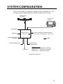
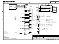
SYSTEM CONFIGURATION
The SC-110 consists of an antenna, a display unit and a processor unit. The
tri-antenna system helps reduce the influence of ship's motion (rolling).
: Option
12-24 VDC
External heading data
6 ports for Heading or Navigation Data
(5 AD-10/IEC 61162 ports, 1 AD-10 port)
Display Unit
SC-502
External DPGS
Beacon Receiver
Processor Unit
SC-1101
Antenna Unit
SC-1203F
Analog roll
Analog pitch
Log/Heading alarm
(Contact)
Category of Units
Processor Unit: Protected from weather
Display Unit: Protected from weather
Antenna Unit: Exposed to weather
System configuration

vi
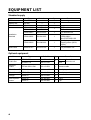
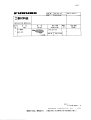
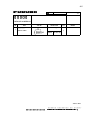
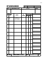
EQUIPMENT LIST
Standard supply
Name Type Code No. Qty Remarks
GPS Antenna SC-1203F 1 Radome type
Display Unit SC-502 1
Processor Unit SC-1101 1
CP20-02230* 004-378-110 TPPX cable
CP20-02260* 004-379-660
1
TNC cable
CP20-02241* 004-378-200 1 For antenna unit
CP20-02600 000-041-905 1
For processor unit:
CP20-02601*,
MJ-A7SPF0006-100
Installation
Materials
CP20-02203* 004-380-660 1
For display unit:
Tapping screw (5X20,
4 pcs.)
Spare Parts SP20-01101* 004-379-720 1 For processor unit
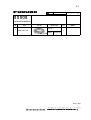
Optional equipment
Name Type Code No. Qty Remarks
CP20-01700 004-372-110 30 m
Antenna
Cable Set
CP20-01710 004-372-120
1
50 m
3 sets, for
antenna unit
Antenna
Cable
TPPX6-3D2V-15M 000-143-559 1 Antenna cable
Flush Mount F OP20-29* 000-041-405 1 For display unit
Flush Mount S OP20-17* 000-040-720 1 For display unit
Flange OP20-31 004-378-230 1
OP20-36 004-380-830 1 4 pcs.
Bird-repellant
fixture
OP20-37 004-380-840 1 1 pc.

SP - 1 E7257-S01-B
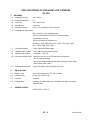
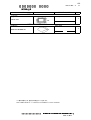
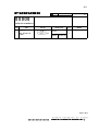
SPECIFICATIONS OF THD SATELLITE COMPASS
SC-110
1 GENERAL
1.1
Heading Accuracy ±0.6° (95%)
1.2 Heading Resolution 0.1°
1.3 Follow-up 45°/s rate-of-turn
1.4 Settling Time 4 minutes
1.5 Position Accuracy 10 m, or 5 m (DGPS), 95% of the time
1.6 Heading/Nav Data Output
AD-10 format: 1 port (specialty port)
AD-10 format 5 ports or IEC 61162 format 10 ports
(selectable on menu)
IEC 61162 format is RS-485 level
Sentence: HDT, HDM, ROT, ATT, VDR, VTG, GGA, GNS
GLL, VHW, VBW, HVE, ZDA
1.7 Log Signal Output 1 port, log pulse (pulse signal)
1.8 Heading Alarm Output 1 port, alarm output (contact signal)
1.9 Motion Output Signal 1 port pitch, 1 port roll
1.10 External Heading Input 1 port AD-10 or IEC 61162 format (auto recognition)
AD-10: backup heading
IEC 61162: water tracking speed input (sentence: HDT, HDG,
HDM, VBW, VHW, VLW)
1.11 External Beacon Input 1 port, RTCM SC-104 format (RS-232 level)
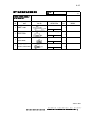
2 DISPLAY UNIT
2.1
Display Type 4.5 inch monochrome LCD, 120 x 64 dots
2.2 Effective Area 60 mm (H) x 95 mm (W)
2.3 Contrast 64 levels
2.4 Display Mode Heading, Nav data, Steering, Compass rose, Rate of turn and
Speed modes
3 POWER SUPPLY
12-24 VDC: 1.2-0.5 A

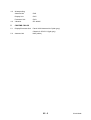
SP - 2 E7257S01B
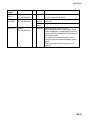
4.3 Waterproofing
Antenna Unit IPX6
Display Unit IPX5
Processor Unit IPX0
4.4 Vibration IEC 60945
5 COATING COLOR
5.1 Display/Processor Unit Panel: N3.0 Newtone No.5 (dark gray)
Chassis: 2.5GY5/1.5 (light gray)
5.2 Antenna Unit N9.5 (white)

1-1
1 INSTALLATION
1.1 Mounting Considerations
1.1.1 Antenna unit
General
•
Keep the length of the antenna cable in mind when selecting a mounting
location.
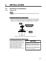
Installing the antenna above superstructures
•
The antenna must be mounted above all other structures on the vessel to
obtain an unobstructed view of the satellites regardless of vessel heading.
Failure to do so will cause shadows and multipath reflection problems.
Mast
Radar Antenna
Bridge
SC-series Antenna
Example of antenna installed above all superstructures
Installing the antenna below superstructures
If it is not possible to mount the
antenna above all superstructures on
the vessel, as shown in the illustration
above, shading and multipath
problems may occur on at least one
heading, and possibly more. To
possibly avoid those problems,
observe the guidelines in this section.
NOTICE
If the antenna is installed below any
superstructure, the installation must
be done over a two-day period, following
the procedure in the service manual.
At least 12 hours are required to capture
tracking data to measure multipath indexes
and locate areas of shading.

1. INSTALLATION
1-2
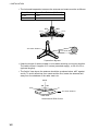
•
The horizontal separation between the antenna and masts must be as follows:
Mast diameter Separation distance (minimum)
10 cm 1.5 m
30 cm 3 m
+80
-80
Less than 10
SC-series Antenna
Mast, etc.
Separation degrees
•
Keep the length of antenna cable in mind when selecting a mounting location.
The cable comes in lengths of 15 meters (standard supply), or 30 m or 50 m
(optional lengths).
•
The field of view above the antenna should be as shown below, ±80° against
zenith. To avoid reflections from masts and the like, locate the antenna well
away from the shadows of the radar mast, etc.
Zenith
-80 +80
SC-series antenna
SIDE VIEW
Antenna and field of view

1. INSTALLATION
1-3
Radar Antenna
SC-series
Antenna
Bridge
Reception blocked by mast.
Location influenced
by reflected wave.
Example of antenna installed below superstructures
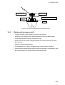
1.1.2 Display unit, processor unit
•
Choose a location where vibration and shock are minimal.
•
Install the units well away from locations subject to rain and water splash.
•
Locate the units away from air conditioner vents.
•
Keep the units out of direct sunlight because of heat that can build up inside
their cabinets.
•
Choose a well-ventilated location.
•
For the display unit, choose a location where it can be easily operated.
•
Leave sufficient space around the units to permit access for maintenance. See
the outline drawing for recommended maintenance space.

1. INSTALLATION
1-4
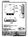
1.2 Installing the Antenna Unit
Note: “Bird-repellent fixtures” may be attached to each antenna element and the
center cover to prevent birds from alighting on them. If it is more
convenient to attach them before fixing the antenna unit to the mounting
location, do step 7 before fixing the antenna unit.
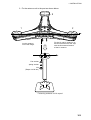
1. Prepare a post for the antenna as shown in the illustration below.
BOW
Bow direction is
between antennas
#1 and #2.
Gasket
(supplied in installation materials)
60.5 mm
15
Recommended Flange
Post should be constructed from
stainless steel and measure
4mm or larger in thickness.
3 mm or less
(Option)
Name: Flange
Type: OP20-31
Code No.: 004-378-230
The width of welding should be
within 3 mm from the mast so
that the welding does not touch
the spring washer.
Weld all the way around.
Installation post

1. INSTALLATION
1-5
2. Fix the antenna unit to the post as shown below.
3
2
1
Set the antenna
unit to the flange.
Fix the #1 and #2 antennas on
the fore-and-aft line of the ship,
with the #2 antenna forward
of the #1 antenna.
Flat washer
Spring washer
Nut
(Torque: 29.58 Nm)
Fastening antenna unit to a post

1. INSTALLATION
1-6
3. Coat each nut, bolt and washer with silicone rubber for waterproofing.
Coat bolt, nut and
washer completely
with silicone rubber.
Coating bolt, nut and washer with silicone rubber
4. As shown below, make a loop in the antenna cable and fasten the antenna
cable to the antenna post with two cable ties.
Fix antenna cable.
Coat with Three
Bond 1211
(supplied).
Coat bolt threads with
Three Bond. Fasten bolt
with nuts and then coat
nuts with Three Bond also.
5. Coat bolt threads with
Three Bond 1211.
Fasten bolts with nuts.
Coat nuts at the
bottom of each
antenna element with
Three Bond 1211.
6. Paint post and support
plate with
anti-corrosive paint.
7. Attach “bird-repellent
fixtures” (supplied) to
each antenna element
and center cover as shown right. Antenna element
Bird-repellent fixture

1. INSTALLATION
1-7
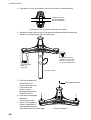
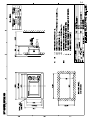
1.3 Installing the Processor Unit
The processor unit should be mounted aligned with the ship’s fore-and-aft line. It
can be mounted on the deck, bulkhead, or on the underside of a desk. Choose a
mounting location which allows you to easily view the power lamp on the top of
the unit and which is within
±
2.5° of the ship’s fore-and-aft line.
1.3.1 Bulkhead mount
The processor unit is shipped from the factory ready for bulkhead mounting.
Orient the processor unit as shown below and fix it to the mounting location with
four tapping screws (M5x20). You will set the orientation later on the menu.
Name Plate (other side)
Reference Direction
Direction
A
Direction B
Direction D
Direction
C
Mounting Method: "Wall"
(Bulkhead)
Mounting Direction: A
Mounting Method: "Wall"
(Bulkhead)
Mounting Direction: B
Mounting Method: "Wall"
(Bulkhead)
Mounting Direction: D
Mounting Method: "Wall"
(Bulkhead)
Mounting Direction: C
Mount processor unit so
reference direction is within
2.5° of fore-and-aft line.
Bulkhead
Bulkhead mount

1. INSTALLATION
1-8
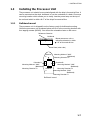
1.3.2 Deck mount
Orient the processor unit as shown below and fix it to the mounting location with
four tapping screws (M5x20). You will set the orientation later on the menu.
Bow
Stern
Stern
Stern
Stern
Port
Starboard
Mounting Method: "Floor"
(Deck)
Mounting Direction: A
Mounting Method: "Floor"
(Deck)
Mounting Direction: B
Mounting Method: "Floor"
(Deck)
Mounting Direction: C
Mounting Method: "Floor"
(Deck)
Mounting Direction: D
Bow
Port
Starboard
Bow
Port
Starboard
Bow
Port
Starboard
Name plate
Connectors
Reference Direction
POWER switch
(power lamp)
Processor Unit, top view
Mount processor unit
so reference
direction is within
2.5 of
fore-and-aft line.
DIRECTION "A" DIRECTION "B"
DIRECTION "C" DIRECTION "D"
Processor unit orientation, deck mounting

1. INSTALLATION
1-9
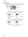
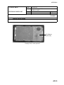
1.3.3 Installation on the underside of a desk
The processor unit may be mounted on the underside of a desk as shown in the
figure below. Do not install it on the overhead.
Name Plate
Desk
Installation of processor unit on the underside of a desk
Bow
Stern
Stern
Stern
Stern
Port
Starboard
Mounting Method: Invert
Mounting Direction: A
Mounting Method: Invert
Mounting Direction: B
Mounting Method: Invert
Mounting Direction: C
Mounting Method: Invert
Mounting Direction: D
Bow
Port
Starboard
Bow
Port Starboard
Bow
Port
Starboard
Name plate (other side)
Connectors
Reference Direction
POWER switch
(power lamp)
Processor Unit, rear view
Mount processor unit so
reference direction is
within
2.5° of
fore-and-aft line.
DIRECTION "A" DIRECTION "B"
DIRECTION "C" DIRECTION "D"
Mounting on underside of desk

1. INSTALLATION
1-10
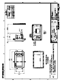
1.4 Installing the Display Unit
1.4.1 Desktop, overhead mounting
1. Fasten the hanger to the mounting location with four tapping screws
(supplied). See the outline drawing for mounting dimensions.
2. Screw the knobs into the display unit.
3. Set display unit to the hanger and tighten the knobs.
4. Run the ground wire between the ground terminal on the display unit and the
ship’s superstructure.
Desktop
Overhead
Display unit mounting methods
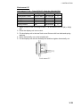
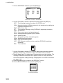
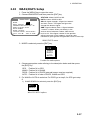
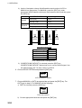
1.4.2 Flush mount
Two types of flush mounts are available. See the outline drawing at the back of
the manual for details.
Flush mount “F”
Flush mount “F” kit Type: OP20-29, Code No: 000-041-405)
Name Type Code No. Qty
Cosmetic Panel 20-016-1051 100-251-370 1
Tapping Screw 5X20 000-802-840 4
Hex Bolt M6X12 000-862-127 2
Spring Washer M6 000-864-260 2
1. Make a cutout in the mounting location. The dimensions are 183(W) x 92(H)
mm.
2. Fasten the cosmetic panel to the display unit with hex bolts and spring
washers.
3. Fasten the display unit to the mounting location with tapping screws.
Page is loading ...
Page is loading ...
Page is loading ...
Page is loading ...
Page is loading ...
Page is loading ...
Page is loading ...
Page is loading ...
Page is loading ...
Page is loading ...
Page is loading ...
Page is loading ...
Page is loading ...
Page is loading ...
Page is loading ...
Page is loading ...
Page is loading ...
Page is loading ...
Page is loading ...
Page is loading ...
Page is loading ...
Page is loading ...
Page is loading ...
Page is loading ...
Page is loading ...
Page is loading ...
Page is loading ...
Page is loading ...
Page is loading ...
Page is loading ...
Page is loading ...
Page is loading ...
Page is loading ...
Page is loading ...
Page is loading ...
Page is loading ...
Page is loading ...
Page is loading ...
Page is loading ...
Page is loading ...
Page is loading ...
Page is loading ...
Page is loading ...
Page is loading ...
Page is loading ...
Page is loading ...
Page is loading ...
Page is loading ...
Page is loading ...
Page is loading ...
Page is loading ...
Page is loading ...
Page is loading ...
Page is loading ...
Page is loading ...
Page is loading ...
Page is loading ...
Page is loading ...
Page is loading ...
Page is loading ...
Page is loading ...
Page is loading ...
Page is loading ...
Page is loading ...
Page is loading ...
Page is loading ...
Page is loading ...
Page is loading ...
Page is loading ...
Page is loading ...
Page is loading ...
Page is loading ...
Page is loading ...
-
 1
1
-
 2
2
-
 3
3
-
 4
4
-
 5
5
-
 6
6
-
 7
7
-
 8
8
-
 9
9
-
 10
10
-
 11
11
-
 12
12
-
 13
13
-
 14
14
-
 15
15
-
 16
16
-
 17
17
-
 18
18
-
 19
19
-
 20
20
-
 21
21
-
 22
22
-
 23
23
-
 24
24
-
 25
25
-
 26
26
-
 27
27
-
 28
28
-
 29
29
-
 30
30
-
 31
31
-
 32
32
-
 33
33
-
 34
34
-
 35
35
-
 36
36
-
 37
37
-
 38
38
-
 39
39
-
 40
40
-
 41
41
-
 42
42
-
 43
43
-
 44
44
-
 45
45
-
 46
46
-
 47
47
-
 48
48
-
 49
49
-
 50
50
-
 51
51
-
 52
52
-
 53
53
-
 54
54
-
 55
55
-
 56
56
-
 57
57
-
 58
58
-
 59
59
-
 60
60
-
 61
61
-
 62
62
-
 63
63
-
 64
64
-
 65
65
-
 66
66
-
 67
67
-
 68
68
-
 69
69
-
 70
70
-
 71
71
-
 72
72
-
 73
73
-
 74
74
-
 75
75
-
 76
76
-
 77
77
-
 78
78
-
 79
79
-
 80
80
-
 81
81
-
 82
82
-
 83
83
-
 84
84
-
 85
85
-
 86
86
-
 87
87
-
 88
88
-
 89
89
-
 90
90
-
 91
91
-
 92
92
-
 93
93


Furuno SC 50 User manual
- Category
- Navigational compasses
- Type
- User manual
- This manual is also suitable for
Ask a question and I''ll find the answer in the document
Finding information in a document is now easier with AI
Related papers
Other documents
-
 Ag Leader Technology GPS 1500 User manual
-
Panasonic C-HDM-101 Installation guide
-
Novatel DL-4plus User guide
-
Raven Phoenix 50 Installation & Operator's Manual
-
 MARINE DATA F069036 User manual
-
Sangean HDT-1 User manual
-
-
Motorola HDT 600 Owner's manual
-
Advantech UTC-532D Installation guide
-
D-Link DPG-1200 - PC-on-TV Media Player User manual

