-4- -5-
LOCATION OF THE BUTTONS
Front Band 1 Level Adjust Button
Front Band 2 Level Adjust Button
Front Band 3 Level Adjust Button
Front Band 1 Frequence Adjust Button
Front Band 2 Frequence Adjust Button
Front Band 3 Frequence Adjust Button
Front Gain Adjust Button
F1-L
F2-L
F3-L
F1-F
F2-F
F3-F
F4
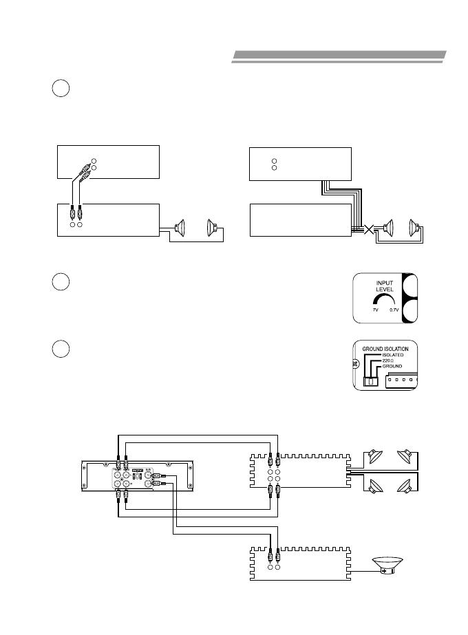
ELECTRONIC CONNECTIONS
If your head player provides
RCA type line out, connect
them to this unit's Line In
socket.
If your head player does not provide RCA
type line out, then disconnect the head
player's speaker leads, connect them to
this unit's High Level Input leads.
Connection to Subwoofer and externa l amplifier
Note: Do not use this unit's low level and high level input together.
CD/Casset te
player
EQ
High Level Input
speake rs
if any
CD/Casset te
player
EQ
Line out
Line in
Note: No low-pass filter is required for the subwoofer amplifier.
3
F1-L F2-L F3-L F4 R4 R1-L R2-L R3-L
3
4
Rear Band 1 Level Adjust Button
Rear Band 2 Level Adjust Button
Rear Band 3 Level Adjust Button
Rear Band 1 Frequence Adjust Button
Rear Band 2 Frequence Adjust Button
Rear Band 3 Frequence Adjust Button
Rear Gain Adjust Button
R1-L
R2-L
R3-L
R1-F
R2-F
R3-F
R4
S-1
S-2
S-3
SUB-Woofer Control
Button
Subwoofer Level Adjust
Button
Subwoofer Frequence
Adjust Button
1
2
3
4
5
Adjust Buttons Position
Switch
Illumination Switch
Power Indicator
Sleep Indicator
Subwoofer On/Off
Switch
F1-F
F2-F
F3-F R1-F R2-F R3-FS2 S3S1
1 25
Front speakers
Rear speakers
Amplifier
Line in
Amplifier
Line in
Subwoofer
Line in
3
2
Adjust the INPUT LEVEL to meet your source unit's
output level. Turn clockwise when your head player has a
normal level output; turn counter-clockwise if your head
player has high level preamp output.
4
Occasionally alternator noise may appear because the
source unit and amplifier may use different grounding. To
help in this situation, you may select the GROUND
ISOLATION switch to a proper position.
300-1.5K 3K-15K30-150
LEVEL
FREQ
Hz
MAXMIN
LEVEL
180
30Hz
FREQ
dB
FRONT
+15-15
Hi
Low
Hi
Low
+15-15
+15-15
Hi
Low
GAIN
MaxMin
GAIN
MaxMin +15-15 +15-15 +15-15
SLEEP
300-1.5K 3K-15K30-150
FREQ
Hz
dB
REAR
Hi
Low
Hi
Low
Hi
Low
LEVEL
POWER ON
SUB-Woofer
Control
ADJADJ
ILLILL
PWM-30M
Parametric Equalizer


