Page is loading ...

www.Fisher.com
Fisherr POSI-SEAL™ A31D Double-Flange
High-Performance Butterfly Valve
Contents
Introduction 1.................................
Scope of Manual 1.............................
Description 2.................................
A31D Valve Specifications and Materials
of Construction 2...........................
Educational Services 2.........................
Installation 3..................................
Valve Orientation 5............................
Before Installing the Valve 5.....................
Adjusting the Actuator Travel Stops or Travel 7.....
Installing the Valve 7...........................
Packing Adjustment and Shaft Bonding 8.........
Maintenance 10................................
Removing and Replacing the Actuator 10.........
Packing Maintenance 11........................
Removing the Valve 11.........................
Seal Maintenance 12...........................
PTFE Seals 12.............................
NOVEX, Phoenix III and/or
Phoenix III Fire-Tested Seals 14............
Anti-Blowout Design, Packing, Valve Shaft,
Disk, and Bearing Maintenance 17.............
Installing the Two-Piece Shaft 20.............
Gasket Retainer 22............................
Parts Ordering 23...............................
Parts List 25...................................
Figure 1. Fisher A31D Valve with 2052 Actuator
X0704
Introduction
Scope of Manual
This instruction manual includes installation, maintenance, and parts ordering information for Fisher POSI-SEAL A31D
double-flange high-performance butterfly valves (see figure 1). Refer to separate instruction manuals for information
covering the actuator and accessories.
Do not install, operate, or maintain an A31D valve without being fully trained and qualified in valve, actuator, and
accessory installation, operation, and maintenance. To avoid personal injury or property d amage, it is important to
carefully read, understand, and follow all the contents of this manual, including all safety cautions and warnings. If you
have any questions about these instructions, contact your Emerson Process Management sales office before
proceeding.
Instruction Manual
D500248X012
A31D Valve
April 2014

Instruction Manual
D500248X012
A31D Valve
April 2014
2
A31D Valve Specifications and Materials of Construction
Table 1. Fisher A31D Valve Specifications
SPECIFICATION
Valve Body Size NPS 3, 4, 6, 8, 10, 12, 14, 16, 18, 20, and 24
Pressure Rating Consistent with CL150 and 300 per ASME B16.34
Valve Body Materials
WCC Steel
CF8M Stainless Steel
Disk Materials CF8M Stainless Steel
End Connections Mates with RF flanges per ASME B16.5
Valve Body Style Double Flange
Shaft Connection
Spline (standard)
Keyed (optional)
Face-to-Face Dimensions
CL150: ISO 5752 Butterfly Valve Short Series
CL300: ISO 5752 Butterfly Valve Long Series
Shutoff
Soft Seal: Bidirectional ANSI/FCI 70-2 Class VI
NOVEX Seal: Unidirectional MSS SP-61
(1)
Phoenix III Seal: ANSI/FCI 70-2 Class VI
Flow Direction Reverse (flow direction is into the shaft side of the disk)
Flow Characteristic Approximately Linear
Disk Rotation Clockwise (CW) to close
1, 0.1 scfh per unit of NPS at 80 psi.
Description
The valve is available in a doubleflanged valve body design, with a variety of seals and internal components. The
pressureassisted seal provides tight shutoff against the full classpressurerangeforthespecifictype.Thesplinedshaft
combines with a variety of Fisher springanddiaphragm or pneumatic double-acting or spring-return piston actuators.
Maximum inlet pressure/temperature ratings are consistent with ASME CL150 and CL300.
Educational Services
For information on available courses for the Fisher POSI -SEAL A31D valve, as well as a variety of other products,
contact:
Emerson Process Management
Educational Services - Registration
P.O. Box 190
Marshalltown, I A 50158-2823
Phone: 800-338-8158 or 641-754-3771
FAX: 641-754-3431
e-mail: edu[email protected]

Instruction Manual
D500248X012
A31D Valve
April 2014
3
Installation
Recommended or ”preferred” installation for the A31D valve is with the flow into the shaft side of the disk (retaining
ring downstream from the high pressure side of the valve).
The standard soft seal and standard Phoenix III seal offer ANSI/FCI 70-2 Class VI, bidirectional shutoff. The Phoenix III
seal for fire-tested applications must be installed in the preferred direction. The Novex seal is unidirectional and should
be installed in the preferred direction. See table 3.
For assistance in selecting the appropriate combination of actuator action and open valve position, consult your
Emerson Process Management sales office.
WARNING
To avoid personal injury or property damage resulting from the sudden release of pressure:
D Always wear protective gloves, clothing, and eyewear when performing any maintenance operations to avoid personal
injury.
D Do not install the valve assembly where service conditions could e xceed the limits given in this manual or on the
nameplates.
D Use pressure-relieving devices as required by government or accepted industry codes and good engineering practices
to protect from over-pressurizing the system.
D Check with your process or safety engineer for any additional measures that must be taken to protect against process
media.
D If installing into an existing application, also refer to the WARNING at the beginning of the Maintenance section in this
instruction manual.
CAUTION
When ordered the valve configuration and construction materials were selected to meet particular pressure, temperature,
pressure drop, and controlled fluid conditions. Responsibility for the safety of process media and compatibility of valve
materials rests solely with the purchaser and end-user. Since some body/trim material combinations are limited in their
pressure drop and temperature range capabilities, do not apply any other conditions to the valve without first contacting
your Emerson Process Management sales office.
1. Isolatethecontrolvalvefromthelinepressure,releasepressure from both sides of the valve body, and drain the
process media from both sides of the valve. If using a power actuator, shut off all pressure lines to the power
actuator, release pressure from the actuator, and disconnect the pressure lines from the actuator. Use lock-out
procedures to be sure that the above measures stay in effect while you are working on the equipment.
WARNING
See the WARNING at the beginning of the Maintenance section for more information before removing the valve from the
pipeline.
2. Install a three-valve bypass around the control valve assembly if continuous operation is necessary during
inspection and maintenance of the valve.
3. Inspect the valve to be certain that it is free of foreign material.

Instruction Manual
D500248X012
A31D Valve
April 2014
4
CAUTION
Damage to the disk will occur if any pipe flanges or piping connected to the valve interfere with the disk rotation path. If
piping flange has a smaller inner diameter than specified for schedule 80 piping, measure carefully to be certain the disk
rotates without interference before placing the valve into operation.
Be certain that adjacent pipelines are free of any foreign material, such as pipe scale or welding slag, that could damage the
valve sealing surfaces.
Installing Double-Flange Valves
WARNING
The edges of a rotating valve disk have a shearing effect that may result in personal injury. To avoid personal injury, keep
clear of the disk edges when rotating the disk.
CAUTION
To avoid damage to the valve disk during installation, the valve must be in the fully closed position. If the A31D valve is
equipped w ith a fail-open actuator, remove the actuator before installing the valve/actuator assembly or cycle the valve
into the fully closed position. Then, take appropriate steps to ensure that the actuator does not cause the valve to open
during installation.
1. See table 2 for flange bolt specifications.
2. Properly orient the valve according to the specific application. For optimum performance, install the valve so that
the shaft will be on the high pressure side of the valve at shutoff.
3. Position the valve between the flanges. Be sure to leave enough room for the flange gaskets. Install the lower flange
bolts.
4. Select the appropriate gaskets for the application. Flat sheet, spiral wound, or other gasket types, made to the
ASME B16.5 group standard or user's standard, can be used on the valve depending on the service conditions of the
application. Install the gaskets and align the valve and the gaskets.
5. Install the remaining bolts.
6. Tighten the flange bolts in an alternating criss-cross fashion to a torque value of one-forth of the final bolting
torque. Repeat this procedure several times increasing the torque value each time by a forth of the final desired
torque. When the final torque value has been applied, tighten each flange bolt again to allow for gasket
compression.
WARNING
An A31D valve body is not grounded when installed in a pipeline. To avoid personal injury or property damage, always
make sure that the valve body is grounded to the pipeline before putting the valve assembly into operation in a flammable
or hazardous atmosphere. To provide shaft and disk-to-body grounding, attach a grounding strap to the shaft w ith a clamp
and connect the other end of the grounding strap assembly to the valve body.
7. If necessary, attach a grounding strap from the valve body or pipeline to the valve shaft. For additional information
on grounding procedures, contact your Emerson Process Management sales office.

A
B
A
Instruction Manual
D500248X012
A31D Valve
April 2014
5
Table 2. Stud Bolt and Cap Screw Chart for Double-Flange Valves
VALVE SIZE, NPS
A31D, CL150, ISO 5752 BUTTERFLY SHORT SERIES
3 4 6 8 10 12 14 16 18 20 24
No. of Through Holes 8 8 8 8 16 16 16 24 24 32 32
No. of Tapped Holes --- 8 8 8 8 8 8 8 8 8 8
Size-Dia. Inch & Thread 5/8 - 11 5/8 - 11 3/4 - 10 3/4 - 10 7/8 - 9 7/8 - 9 1-8 1-8 1-1/8 1-1/8 1-1/4 - 8
No. of Stud Bolts 8 8 8 8 16 16 16 24 24 32 32
A-Length of Stud Bolts
(1)
,Inch 4 4-1/2 4-3/4 4-3/4 5-1/2 5-1/2 5-3/4 5-3/4 6-1/4 6-1/2 7-3/8
No. of Cap Screws --- 8 8 8 8 8 8 8 8 8 8
B-Length of Cap Screws
(2)
,Inch --- 2-1/2 2-1/2 2-3/4 3 3 2-3/4 3 3-1/4 3-1/4 3-3/4
No. of Heavy Hex Nuts 16 16 16 16 32 32 32 48 48 64 64
VALVE SIZE, NPS
A31D, CL300, ISO 5752 BUTTERFLY LONG SERIES
3 4 6 8 10 12 14 16 18 20 24
No. of Through Holes 16 16 24 24 32 24 32 32 40 40 40
No. of Tapped Holes --- --- --- --- --- 8 8 8 8 8 8
Size-Dia. Inch & Thread 3/4 - 10 3/4 - 10 3/4 - 10 7/8 - 9 1-8 1-1/8 - 8 1-1/8 - 8 1-1/4 - 8 1-1/4 - 8 1-1/4 - 8 1-1/2 - 8
No. of Stud Bolts 16 16 24 24 32 24 32 32 40 40 40
A-Length of Stud Bolts
(1)
,Inch 4-1/2 5 5-1/4 6 6-3/4 7-1/4 7-1/2 8 8-1/2 8-3/4 9-3/4
No. of Cap Screws --- --- --- --- --- 8 8 8 8 8 8
B-Length of Cap Screws
(2)
,Inch --- --- --- --- --- 4-3/4 4-3/4 4-1/4 4-1/4 4-1/2 5
No. of Heavy Hex Nuts 32 32 48 48 64 48 64 64 80 80 80
1. Based on
1/8-inch gasket
2. Optional Alternative for Cap Screws
Valve Orientation
The valve can be installed in any orientation, however, it is recommended that the valve drive shaft be horizontal and
the actuator vertical.
Before Installing the Valve
WARNING
The edges of a rotating valve disk (key 2, figure 9, 10, or 11) close with a shearing, cutting motion. To avoid personal injury,
keep hands, tools, and other objects away from the disk while stroking the valve.
If the A31D valve is equipped with a fail-open actuator, cycle the valve into the fully closed position. Ensure the valve
cannot open during installation by using travel stops, a manual actuator, a constant supply pressure to the pneumatic
actuator, or other steps as necessary.

Instruction Manual
D500248X012
A31D Valve
April 2014
6
Figure 2. Available Seal Configurations
NOTE:
FOR OPTIMUM SEAL PERFORMANCE, THE PREFERRED VALVE ORIENTATION AT SHUTOFF IS WITH THE RETAINING RING DOWNSTREAM FROM THE HIGH PRESSURE SIDE OF THE VALVE.
1
PHOENIX III
FIRE-TESTED SEAL
NOVEX SEAL
SOFT SEAL WITH
BACKUP O-RING
BACKUP
RING
BACKUP
RING
SEAL RING
RETAINING
RING
RETAINING
RING
RETAINING
RING
HIGH PRESSURE
AT SHUTOFF
HIGH PRESSURE
AT SHUTOFF
HIGH PRESSURE
AT SHUTOFF
METAL
SEAL
RING
RESILIENT INSERT
NOVEX
SEAL RING
VALVE DISK
VALVE DISK
VALVE DISK
BODY
BODY
BODY
1
1
1
Table 3. Valve Orientation forOptimalSealPerformance
SEAL TYPE SHUTOFF DIRECTION INSTALLED ORIENTATION
Standard soft seal Bidirectional Preferred
Novex seal Unidirectional Preferred only
Phoenix III seal
Bidirectional
Non Fire-Tested
Preferred
Unidirectional Fire-Tested Preferred
Recommended or ”preferred” installation for the A31D valve is with the flow into the shaft side of the disk (retaining ring downstream from the high pressure side of the valve).

Instruction Manual
D500248X012
A31D Valve
April 2014
7
Table 4. Valve Weights
SIZE CL150 CL300
NPS kg lb kg lb
3 15 33 28 63
4 25 56 35 77
6 34 76 65 143
8 54 118 156 343
10 81 178 176 388
12 110 243 294 649
14 152 335 345 760
16 201 443 563 1240
18 243 535 591 1303
20 277 611 706 1556
24 434 956 1307 2881
An A31D valve is normally shipped as part of an assembly with an actuator and other accessories such as a valve
positioner. If the valve and actuator have been purchased separately or if the actuator has been removed for
maintenance, properly mount the actuator and adjust valve/actuator travel and all travel stops before inserting the
valve into the line.
CAUTION
Damage to the disk will occur if any pipe flanges or piping connected to the valve interfere with the disk rotation path. Be
certain to align the valve accurately to avoid contact between the disk (key 2) and the flanges.
Adjusting the Actuator Travel Stops or Travel
Key number locations are shown in figure 9, 10, or 11, unless otherwise noted.
1. Refer to the actuator instruction manual to locate the actuator travel stop that controls the closed position of the
valve disk (key 2). When adjusting the travel stop or travel, make sure that the disk is from 0.25 to 0.76 mm (0.010
to0.030inch)awayfromtheinternalstopinthevalvebody(seefigure5).Thisadjustmentisnecessarytobe
certain that the actuator output torque is fully absorbed by the actuator travel stop or by the actuator. The internal
travel stop in the valve body should not absorb any of the actuator torque.
CAUTION
When using an actuator, the actuator travel stop (or actuator travel, for actuators without adjustable stops) must be
adjusted so the disk stop in the valve does not absorb the output of the actuator. Failure to limit the actuator travel as
described in the Adjusting the Actuator Travel Stops or Travel steps can result in damage to the valve, shaft(s), or other
valve components.
2. Before installing the valve/actuator assembly in the process line, cycle the valve several times to be sure the valve
disk returns to the proper position.
Installing the Valve
The maximum allowable inlet pressures for A31D valves are consistent with the applicable ASME
pressure/temperature ratings except where limited by the material capabilities.

Instruction Manual
D500248X012
A31D Valve
April 2014
8
Refer to table 2 for the quantity and size of line bolting required to install the valve i n the pipeline.
CAUTION
To avoid damage to the valve disk during installation, the valve must be in the fully closed position. If the A31D valve is
equipped w ith a fail-open actuator, remove the actuator before installing the valve/actuator assembly or cycle the valve
into the fully closed position. Then, take appropriate steps to be sure that the actuator does not cause the valve to open
during installation.
Figure 3. Properly Installed Valve
GE62595-A
1. Seefigure3forrecommendedvalveorientation.
2. Position the valve between the flanges. Be sure to leave enough room for the flange gaskets. Install the lower flange
bolts.
3. Select the appropriate gaskets for the application. Flat sheet, spiral wound, or other gasket types, made to the
ASME B16.5 standard or user's standard, can be used on A31D valves depending on the service conditions of the
application.
4. Install the remaining flange bolts.
5. Tighten the flange bolts in an alternating criss-cross fashion to a torque value of one-fourth of the final bolting
torque. Repeat this procedure several times, increasing thetorquevalueeachtimebyafourthofthefinaldesired
torque. After applying the final torque value, tighten each flange bolt again to allow for gasket compression.
Packing Adjustment and Shaft Bonding
WARNING
Personal injury could result from packing leakage. Valve packing was tightened before shipment; however, the packing
might require some readjustment to meet specific service c onditions. Check with your process of safety engineer for any
additional measures that must be taken to protect against process media.
1. For PTFE or graphite packing: Tighten standard packing follower nuts only enough to prevent shaft leakage.
Excessive tightening of packing will accelerate wear and could produce higher rotating friction loads on the valve
stem. If necessary, refer to the Packing Maintenance section.

Instruction Manual
D500248X012
A31D Valve
April 2014
9
Figure 4. Optional Shaft-to-Valve Body Bonding Strap Assembly
VALVE BODY
ACTUATOR
A
A
VIEW A-A
37A6528-A
A3143-2
CAUTION
For non-ENVIRO-SEAL packing: Tighten the packing follower nuts only e nough to prevent shaft leakage. Excessive
tightening will accelerate wear of the packing and could produce higher friction loads on the valve stem.
2. ENVIRO-SEAL Packing Systems: will not require this initial re-adjustment. Refer to the separate instruction manual,
Fisher ENVIRO-SEAL Packing System for Rotary Valves (D101643X012), for repair and adjustment procedures.
3. For hazardous atmosphere or oxygen service valves, read the following Warning, and provide the bonding strap
assembly mentioned below if the valve is used in an explosive atmosphere.
WARNING
The valve shaft is not necessarily grounded when installed in a pipeline unless the shaft is electrically bonded to the valve.
To avoid personal injury or property damage resulting from the effects of a static electricity discharge from valve
components in a hazardous atmosphere or where the process fluid is combustible, electrically bond the drive shaft (key 3)
to the valve according to the following step.

Instruction Manual
D500248X012
A31D Valve
April 2014
10
Note
Standard PTFE packing is composed of a partially conductive carbon-filled PTFE female adaptor with PTFE V-ring packing. Standard
graphite packing is composed of all conductive graphite ribbon packing. Alternate shaft-to-valve body bonding is available for
hazardous service areas where the standard packing is not sufficient to electrically bond the shaft to the valve (see the following
step).
4. Attach the bonding strap assembly (key 131, figure 4) to the shaft with the clamp (key 130, figure 4).
5. Connect the other end of the bonding strap assembly to the valve flange cap screws.
6. For more information, refer to the Packing Maintenance section below.
Maintenance
Valve parts are subject to normal wear and must be inspected and replaced as necessary. The frequency of inspection
and replacement depends upon the severity of service conditions.
Key numbers in this procedure are shown in figure 9, 10, or 11 unless otherwise indicated.
WARNING
The valve closes with a shearing action. To avoid personal injury, keep hands, tools, and other objects away from the valve
while its being stroked.
Avoid personal injury from sudden release of process pressure. Before performing any maintenance operations:
D Do not remove the actuator from the valve while the valve is still pressurized.
D Always wear protective gloves, clothing, and eyewear when performing any maintenance operations to avoid personal
injury.
D Disconnect any operating lines providing air pressure, electric power, or a control signal to the actuator. Be sure the
actuator cannot suddenly open or close the valve.
D Use bypass valves or completely shut off the process to isolate the valve from process pressure. Relieve process pressure
on both sides of the valve. Drain the process media from both sides of the valve.
D Vent the power actuator loading pressure.
D Use lock-out procedures to be sure that the above measures stay in effect while you work on the equipment.
D The valve packing box may c ontain process fluids that are pressurized, even when the valve has been removed from the
pipeline. Process fluids may spray out under pressure when removing the packing hardware or packing rings, or when
loosening the packing box pipe plug.
D Check with your process or safety engineer for any additional measures that must be taken to protect against process
media.
Removing and Replacing the A ctuator
Refer to the appropriate actuator instruction manual for actuator removal and replacement procedures. The actuator
stops or travel stops must limit the rotation of the valve shaft. See the CAUTION below.
CAUTION
When using an actuator, the actuator travel stop (or actuator travel stop, for actuators without adjustable stops) must be
adjusted so the disk stop in the valve does not absorb the output of the actuator. Failure to limit the actuator travel can
result in damage to the valve, shaft(s), or other valve components.

Instruction Manual
D500248X012
A31D Valve
April 2014
11
Packing Maintenance
TheA31Dvalveisdesignedsothepackingcanbereplacedwithoutremovingthevalvefromtheprocesspipeline.
CAUTION
For non-ENVIRO-SEAL packing: Tighten the packing follower nuts only e nough to prevent shaft leakage. Excessive
tightening will accelerate wear of the packing and could produce higher friction loads on the valve stem.
Usually, packing leakage can be eliminated by m erely tightening the hex n uts (key 15) located above the packing
follower (key 12) while the valve is in the pipeline. However, if leakage continues, the packing must be replaced.
For PTFE ENVIRO-SEAL packing system, refer to instruction manual, Fisher ENVIRO-SEAL Packing System for Rotary
Valves (D101643X012) (see figure 8).
CAUTION
Never use a wrench or pliers on the drive shaft (key 3). A damaged shaft could c ut the packing and a llow leakage.
1. Before loosening any parts on the valve, release the pressure from the pipeline. Then, remove the hex nuts (key 15)
and lift off the packing follower (key 12).
2. Remove the hex jam nuts (key 17) and the anti-blowout flange (key 10). Remove the packing follower (key 12).
Refer to figure 6 for details of the anti-blowout protection parts.
The packing is now accessible.
3. Use a packing extractor to remove packing. Insert the corkscrew-like end of the tool into the first piece of packing
and pull firmly to remove the packing. Repeat this process until all packing parts have been removed.
CAUTION
Be careful when cleaning the packing box. Scratches to the drive shaft (key 3) or inside diameter of the packing bore might
cause leakage.
4. Before installing new packing, clean the packing box.
5. Install new packing one ring at a time, using the packing follower as a driver. If using split-ring packing, stagger the
splitsintheringstoavoidcreatingaleakpath.
6. Reinstall the packing parts. Refer to figure8forthesequenceofpackingparts.
Removing the Valve
1. Disconnect any operating lines providing air pressure, electric power, or a control signal to the actuator. Be sure the
actuator cannot suddenly open the valve. Vent the power actuator loading pressure.
2. Use bypass valves or completely shut off the process to isolate the valve from process pressure. Relieve process
pressure on both sides of the valve. Drain the process media from either side of the valve.

Instruction Manual
D500248X012
A31D Valve
April 2014
12
CAUTION
Damage to the valve disk can occur if the disk is not closed when the valve is being removed from the pipeline. If necessary,
stroke the actuator to place the disk in the closed position while removing the valve from the pipeline.
3. Loosen the flange bolting that holds the valve. Make sure the valve cannot slip or twist while loosening and
removing the bolting.
4. Before removing the valve from the pipeline, make sure the valve disk is closed. Removing the valve with the disk
open could cause damage to the disk, piping, or pipe flanges.
5. After removing the valve from t he pipeline, move the valve to an appropriate work area. Always support the valve
properly.
6. When valve maintenance is complete, refer to the Installation procedures in this manual.
Seal Maintenance
Note
For larger valves, it is possible to replace the seal (key 5) while the actuator is mounted to the valve and can be accomplished by
cycling the valve to 90 d egrees open.
Key numbers in this procedure are shown in figure 9, 10, or 11 unless otherwise indicated.
1. After removing the valve from the pipeline, remove the manual or power actuator. Manually rotate the drive shaft
(key 3) counterclockwise until the disk has moved a full 180 degrees away from the closed position.
WARNING
Avoid personal injury or property damage caused by the impact of a falling or tipping of a large valve. Support large valves
during maintenance.
2. Lay the valve flat on a work bench in a secure position with the retaining ring (key 18) and retaining ring screws (key
19) facing up. Properly secure the valve on a suitable worktable so it cannot slip, twist, or fall during maintenance.
Remove all retaining ring screws.
3. Remove the retaining ring by placing a socket head cap screw from the retaining ring into each of the two retaining
ring jacking screw holes. Slowly turn the screws until the retaining ring has been lifted from the valve body. Remove
the retaining ring to expose the seal in the T-slot area of the valve body.
Note
The A31D is available with different seal designs and components. See figure 2 to identify t he specific seal design.
4. Insert a regular screwdriver or other similar tool under the top edge of seal and gently pry the seal out of the T-slot
area in the valve body. Take care not to damage the seal or T-slot area of the valve body. After the seal has been
removed, clean the T-slot area, retaining ring and, if required, polish the disk (key 2) thoroughly.

Instruction Manual
D500248X012
A31D Valve
April 2014
13
To install a new seal, O-ring (key 6), and retaining ring gasket, follow the appropriate instructions given below.
Table 5. Torque Values for Retaining Ring Screws
ASME CLASS AND VALVE SIZE, NPS
RETAINING RING SCREWS
Fastener Nominal Size N•m Lbf•in
CL150: NPS 3, 4, 8, and 10; NPS 3 and 4 #10 4.6 41
CL150: NPS 6 and 12; CL300:NPS 6, 8, 10, and 12 1/4 11 100
CL150: NPS 14, 16, 18, 20, and 24; CL300: NPS 14 and 16 5/16 25 220
CL300: NPS 18 and 20 3/8 45 400
CL300: NPS 24 1/2 112 996
Note: These values are based upon standard materials, S66286/N07718 s crews and ASTM A193GRB6 bolts. Fo r other special fastener materials, please contact your Emerson Process
Management sales office.
Table 6. Torque Values for Gasket Retainer Bolts
ASME CLASS AND VALVE SIZE, NPS
GASKET RETAINER BOLTS
Fastener Nominal Size N•m Lbf•in
CL150: NPS 3 and 10; NPS 3 5/16 19 167
CL150: NPS 4, 6, 8, 12, 14, 16, 18, 20, 24; CL300:NPS 4, 6, 8, 10, 12, 14 3/8 33 295
CL300: NPS 16 and 18 1/2 80 708
CL300: NPS 20 and 24 5/8 161 1428
Note: These values are based upon standard materials, S66286/N07718 s crews and ASTM A193GRB6 bolts. Fo r other special fastener materials, please contact your Emerson Process
Management sales office.
Figure 5. Typical Seal Installation
INTERNAL TRAVEL STOP
LARGEST OUTSIDE
DIAMETER (KEY 5)
CCW DISK
ROTATION
TO OPEN
ACTUATOR END
OF SHAFT
POSITION INDICATION MARK
INDICATES APPROXIMATE
DISK POSITION
GE62591-A
0.25 TO 0.76
(0.010 TO 0.030)
mm
(inch)
PTFE Seals
1. Locate the replacement seal ring (key 5) and note the shape of the ring. The ring is wider across one edge diameter
andnarroweracrosstheotheredgediameterasshowninfigure5.Aroundtheoutsidecircumferenceisonewide
groove.
Before installing the seal ring into the valve body, place the O-ring (key 6) into the wide, outer groove of the seal ring.
Refer to figure 5.

Instruction Manual
D500248X012
A31D Valve
April 2014
14
2. Install the seal ring and O-ring assembly in the valve body. The wider outside diameter of the seal ring, as marked in
figure 5, goes into the T-slot area of the body. Start the edge with the wider diameter into the T-slot of the valve
body using a blunt-end tool.
3. Carefully tuck the O-ring downward into the body T-slot until the seal ring is completely entrapped in the body
T-slot, and it completely covers the backup O-ring.
4. Re-install the retaining ring and the socket head cap screws. Tighten the cap screws just enough to eliminate any
movement of the retaining ring. Do not over-tighten the retaining ring screws. Using a blunt-end tool, carefully
tuck the lip of the seal ring under the retaining ring.
5. When the seal is under the lip of the retaining ring, continue to tighten the cap screws according to standard
procedures. Do not fully torque screws at this time. Final tightening of screws is accomplished in step 7 of this
procedure.
6. Manually rotate the drive shaft clockwise 180 degrees to return the disk (key 2) to its closed position.
7. The final seating of the retaining ring cap screws can now be done. For the screw torque values, refer to table 5. The
seal is now fully installed. Refer to the Installation procedures in this manual.
NOVEX, Phoenix III and/or Phoenix III Fire-Tested Seals
1. Locate the replacement seal ring (key 5) and note the shape of the ring. The ring is wider across one edge diameter
andnarroweracrosstheotheredgediameterasshowninfigure5.Aroundtheoutsidecircumferenceisonewide
groove.
Install the seal ring (key 5) in the valve body by first placing the wider outside diameter of the seal ring into the T-slot
area of the valve body which is shown in figure 2.
The backup O-ring (key 6) for the Phoenix III seal will have to be installed after placement of the seal ring in the valve
body using a blunt-end tool. Do not use the seal tool directly on the metal seat. Use tools on the O-ring only.
2. With the seal ring inserted all the way around the body T-slot now lay the O-ring into the opening between the valve
body and the seal ring. Use the seal tool to apply pressure to the O-ring and carefully tuck the O-ring down into the
T-slot between the valve body and the seal ring.
Note
On larger valves, it may be more efficient to have someone hold down the seal ring while you push the O-ring into the T-slot.
3. Once the seal ring and backup O-ring have been fully installed into the body T-slot, the retaining ring gasket can be
installed. This gasket is a thin graphite material. Punch one initial screw hole through the gasket for alignment,
being careful not to cause additional damage to the gasket.
CAUTION
The retaining ring gasket is a thin graphite material. When you punch one initial screw hole through the gasket for
alignment, be careful not to cause additional damage to the gasket.
4. Install the retaining ring and align the screw holes in the retaining ring with the holes in the valve body. Install the
first retaining ring screw through the punched hole in the ring gasket. Install the other ring screws by pushing the
screws through the graphite gasket and threading them into the valve body.
5. Tighten the retaining ring socket head cap screws just enough to eliminate any movement of the retaining ring. Do
not over-tighten the retaining ring screws.

Instruction Manual
D500248X012
A31D Valve
April 2014
15
WARNING
Avoid personal injury or property damage caused by the impact of a falling or tipping of a large valve. Support large valves
during maintenance.
6. To complete this step, stand the valve up. Support the valve securely using methods appropriate for the valve size.
Ifaviseorotherclampsarebeingused,besuretonotdamagetheflangegasketsealingareaofthevalvebody.
7. Manually rotate the drive shaft (key 3) to turn the disk clockwise to meet the seal.
8. Tap the disk with a rubber mallet to drive it against the internal travel stop. When the disk makes contact with the
stop, manually rotate the disk counterclockwise back out of the seal to a 90-degree open position. Repeat steps 7
and 8 three times.
Note
When attaching the actuator to the valve, make sure the valve disk is not in contact with the valve internal travel stop (see figure
5). The valve disk should be positioned from 0.25 to 0.76 mm (0.010 to 0.030 inch) away from the internal stop in the valve body
(see figure 5).
9. Use an appropriate tool (such as a feeler gauge) to position the disk (key 2) from 0.25 to 0.76 mm (0.010 to 0.030
inch) away from the internal stop in the valve body.
This adjustment is necessary to be certain that the actuator output torque is fully absorbed by the actuator travel stop
or by the actuator. The internal travel stop in the valve body should not absorb any of the actuator t orque.
CAUTION
When using an actuator, the actuator travel stop (or actuator travel, for actuators without adjustable stops) must be
adjusted so the disk stop in the valve does not absorb the output of the actuator. Failure to limit the actuator travel as
described in the Adjusting the Actuator Travel Stops or Travel steps can result in damage to the valve, shaft(s), or other
valve components.
10. The final seating of the retaining ring screws can now be done. For the screw torque values, refer to table 5.

Instruction Manual
D500248X012
A31D Valve
April 2014
16
Figure 6. Anti-Blowout Design Details
PACKING
FLANGE
ANTI-BLOWOUT
FLANGE
SHAFT
SHOULDER
SHAFT
HEX NUT
STUD
PACKING
FOLLOWER
HEX NUT
TYPICAL PTFE V-RING
PACKING
HEX NUT
PACKING
FLANGE
SHAFT
SHOULDER
STUD
HEX NUT
ANTI-BLOWOUT
FLANGE
SPRING PACK
ASSEMBLY
PACKING
SET
ANTI-EXTRUSION
RING
PACKING
BOX RING
LUBRICANT
A7090
STANDARD PACKING ARRANGEMENT
CUTAWAY, NPS 14 THROUGH 24
ENVIRO-SEAL ARRANGEMENT (PTFE SHOWN)
NPS 14 THROUGH 24
STANDARD PACKING ARRANGEMENT
CUTAWAY, NPS 3 THROUGH 12
ENVIRO-SEAL ARRANGEMENT (PTFE SHOWN)
NPS 3 THROUGH 12
PACKING
FLANGE
ANTI-
BLOWOUT
FLANGE
ANTI-
BLOWOUT
RING
PACKING
FOLLOWER
TYPICAL
PACKING
VALVE
BODY
C0766
PACKING
FLANGE
SPRING PACK
ASSEMBLY
ANTI-BLOWOUT
RING
TYPICAL
PACKING
STUD AND
HEX NUT
HEX JAM
NUT
ANTI-BLOWOUT
FLANGE
VALVE BODY
B2449

Instruction Manual
D500248X012
A31D Valve
April 2014
17
Anti-Blowout Protection, Packing, Valve Shaft(s), Disk, and Bearing
Maintenance
Removal
Note
NPS 3 through 8 valves (CL150) and NPS 3 through 6 valves (CL300) have a bearing stop pressed into the bearing bore
immediately after the packing box.
Do not attempt to remove the bearing stop which is found in the drive shaft bearing bore immediately after the packing box. The
bearing stop is pressed into the bearing bore. If the bearing stop needs replacement, contact your Emerson Process Management
sales office for more information.
Note
The A31D valve has a two-piece shaft. In these procedures, the drive shaft is key 3. The shaft opposite the drive shaft is called the
follower shaft (key 4).
CAUTION
When using an actuator, the actuator travel stop (or actuator travel adjustment, for actuators without adjustable stops)
must be adjusted so the disk stop in the valve does not absorb the output of the actuator. Failure to limit the actuator travel
as described in the next step can result in damage to the valve, shaft(s), or other valve components.
CAUTION
When removing the actuator from the valve, do not use a hammer or similar tool to drive the lever off the valve shaft.
Driving the lever or actuator off the valve shaft could damage the valve internal parts.
If necessary, use a wheel puller to remove the lever or actuator from the valve shaft. It is okay to tap the wheel puller screw
lightly to loosen the lever or actuator, but hitting the screw with excessive force could also damage internal valve parts.
Key numbers in this procedure are shown in figure 9, 10, or 11 unless otherwise indicated.
1. Remove the valve from the pipeline. Remove the actuator from the valve.
WARNING
Avoid personal injury or property damage caused by the impact of a falling or tipping of a large valve. Support large valves
during maintenance.
CAUTION
Never use a wrench, pliers, or similar tool to turn the drive shaft. A damaged shaft can cut the packing and allow leakage.

Instruction Manual
D500248X012
A31D Valve
April 2014
18
Note
It is not necessary to remove the retaining ring and valve seal when removing the shaft(s) and disk.
2. Properly secure the valve on a suitable worktable so it cannot slip, twist, or fall during maintenance.
3. Removing the Anti-Blowout Design:
a. For PTFE or Graphite Packing: Remove the hex nuts (key 15) and pull off the packing flange (key 11). R emove the
hex jam nuts (key 17) and the anti-blowout flange (key 10). Remove the packing follower (key 12). For NPS 3
through 12, remove the anti-blowout ring (key 16), see figure 6.
b. For ENVIRO-SEAL Packing System: Remove the hex nuts (key 101), the packing flange (key 102), jam nuts (key
17), anti-blowout flange (key 10), and the spring pack assembly (key 103). For NPS 3 through 12, remove the
anti-blowout ring (key 16), see figures 6 and 8.
4. Remove the packing from around the drive shaft.
Note
Different valves require slightly different procedures because different valve sizes/ pressure classes have different methods of
connecting the disk and shaft(s). To identify the proper procedures, refer to the list below.
D CL150, NPS 3 through 8: One-piece shaft with 1 t aper key, (see figure 9).
D CL150, NPS 10 and 12: Two-piece shaft. 1 taper key in the drive shaft; 1 tangential pin in the follower shaft, (see figure 10).
D CL150, NPS 14 through 24: Two-piece shaft with 2 tangential pins in t he drive shaft; 1 tangential pin in the follower shaft,
(see figure 11).
D CL300, NPS 3 through 6: One-piece shaft with 1 t aper key, (see figure 9).
D CL300, NPS 8 and 10: Two-piece shaft. 1 taper key in the drive shaft; 1 tangential pin in the follower shaft, (see figure 10).
D CL300, NPS 12 through 24: Two-piece shaft with 2 tangential pins in the drive shaft; 1 in the follower shaft, (see figure 11).
5. Proceed as appropriate, using the following instructions.
For valves with taper key, locate the taper key (key 9, figure 7) which runs through the drive shaft boss on the back of
the valve disk. Using a pin punch on the smaller end of the key, drive it out of the disk and shaft. Driving a taper key in
the wrong direction will tighten it.
Note
Certain valve sizes may have a taper key that is arc spot welded in place. To remove the key, use a punch on the smaller end of the
taperkeyanddriveitoutofthediskandshaft,breakingtheweld.
For valves with tangential pins, locate the tangential pins (key 25) in the drive shaft (key 3) and the tangential pin
(key 25) in the follower shaft (key 4).
a. Use a threaded rod with an appropriate spacer and nut as an extractor tool to remove the tangential pins. If using
a threaded rod, choose a rod with threads that fit the inside thread of the pins. The rod should extend several
inches above the disk when it is screwed into a pin.

Instruction Manual
D500248X012
A31D Valve
April 2014
19
b. After screwing the rod into the pin, slide the spacer over the rod and pin. Thread the nut onto the rod and tighten
it. As the nut is tightened, the nut will drive the spacer against the disk. The i ncreasing force will draw the pin
from the disk.
1. Valves with a two-piece shaft have a gasket retainer and gasket (keys 20 and 21) on the follower shaft side of the
valve. Remove the hex head bolts and lockwashers (keys 23 and 22) from the gasket retainer and remove the gasket
retainer and gasket to expose the end of the follower shaft.
2. Support the valve disk properly, and remove the follower shaft. Pull the follower shaft from the valve body. Use a
shaft extractor screwed into the puller hole in the end of the follower shaft.
3. Support the valve disk properly, and remove the drive shaft. Pull out the drive shaft (key 3) by hand-pulling or by
using a shaft extractor screwed i nto the end o f the shaft.
CAUTION
To avoid damage to the disk, seal ring, and T-slot area, do not force the disk past the seal or T-slot area. Remove the disk
from the opposite side of the valve body.
4. After removing the shaft(s), remove the disk and the thrust bearings. Do not force the disk past the seal ring or
T-slot area.
5. Remove the journal bearings (key 7). Using a suitable punch or puller, drive or pull the journal bearing(s) into the
valvebodyborefromthedriveshaftbearingbore.Donotattempttoremovethebearingstop(key8).Removethe
journal bearing from the follower shaft bearing bore.
6. Inspect the valve body bore, bearings, bearing bores, and packing box for damage.
Installing a One-Piece Shaft
Unless otherwise indicated, key numbers and part names are listed in figure 7.
1. Secure the valve in an upright position. Allow for easy access to the valve body bore. Allow for easy access to the
drive shaft bearing bore.
2. Inspect all parts removed from the valve for wear or damage. Replace any worn or damaged parts. Clean the valve
body and all parts to be installed with an appropriate solvent or degreaser.
CAUTION
Premature valve failure and loss of process control may r esult if bearings are improperly installed or are damaged during
installation.
3. Using caution to prevent damage to the bearing, insert one journal bearing (key 7) from the valve body bore into
the drive shaft bearing bore until it hits the bearing stop (key 8). When properly installed, a portion of the journal
bearing will extend into the valve body bore.
4. Insertonejournalbearingfromthevalvebodyboreintotheshaftbearingboreoppositethejournalbearing
installed in step 3. When correctly installed, this journal bearing will be flush with the valve body bore.
5. Installthevalvediskbyplacingthediskintothevalvebodyboresothecurvedsideofthediskpassesthroughthe
end of the valve body that does not contain the T-slot. Align the shaft bore in the disk with the bearing bores.
6. Insertthedriveshaftendoppositethesplinedendintothevalvebodythroughthepackingbox.Pushtheshaft
through the bearing stop. Taking care not to dislodge the journal bearing, push the shaft through the journal
bearing and the valve disk and into the bore on the opposite side of the valve body.

Instruction Manual
D500248X012
A31D Valve
April 2014
20
CAUTION
To avoid damage to the taper key, tangential pins, valve disk, or shaft(s) resulting from the application of excessive force,
use appropriate care when driving the key or pins into the disk hub and shaft(s). Use the right tool. Do not use excessive
force.
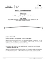
7. Be sure the taper key disk shaft joint is free of oil or grease. If necessary, remove any excess welding material from
the taper key.
8. Alignthetaperkeyholeintheshaftwiththeholesintheshaftbossonthedisk.Insertthetaperkey.Useaflat-end
punch to drive the taper key until solid contact is felt. Measure the depth of the taper key head for a reference
during the following steps.
a. Drive the taper key in farther as follows:
VALVE SIZE, NPS MINIMUM DEPTH TO DRIVE TAPER KEY AFTER INITIAL SOLID CONTACT
CL150 and 300, NPS 3, 4, 6 valves, & NPS 8 CL150 valves 5 mm (0.188 INCHES)
b. The disk shaft, and taper key assembly must be inspected to verify that the taper key spans t he entire shaft flat
width. If so, this procedure is complete. If not, the taper key must be driven in farther until this condition is
satisfied. However, do not exceed the following depth limits:
VALVE SIZE, NPS MAXIMUM ALLOWABLE DEPTH TO DRIVE TAPER KEY AFTER INITIAL SOLID CONTACT
NPS 3 and 4 CL150/300 7 mm (0.281 INCHES)
NPS 6 CL300, and NPS 8 CL150 8 mm (0.312 INCHES)
9. After driving the taper key in place, arc spot weld the head of the taper key to the disk as shown in figure 7. For NPS
3, 4, and 6 valves, use an arc spot weld bead of 1/8-inch diameter. For NPS 8, 10,and12valves,useanarcspotweld
bead of 3/16-inch diameter.
10. Install the packing as described in the Packing Replacement section or in the ENVIRO-SEAL Rotary Packing
Instruction Manual (D101643X012).
Figure 7. Fisher A31D Taper Key Weld Location
A5947
WELD LOCATION
WELD
LOCATION
TAPER KEY
SHAFT
DISK
MINIMUM TAPER KEY ENGAGEMENT
MAXIMUM TAPERKEYENGAGEMENT
VIEW A
TAPER KEY WELD LOCATION
Installing the Two-Piece Shaft
Note
In these instructions, the drive shaft (with splined or keyed end) is key 3. The shaft opposite the drive shaft is called the follower
shaft (key 4).
/