Page is loading ...

IMPORTANT: Read all instructions carefully before using this product.
Retain this owner’s manual for future reference.
The specifications of this product may vary from this photo, subject to
change without notice.
2638.1-052919
MAGNGETIC MOMENTUM
ROWER MACHINE


1
SERVICE ------------------------------------------------------------------------
2
LABEL PLACEMENT----------------------------------------------------------
3
IMPORTANT SAFETY GUIDELINES ------------------------------------
4
OVERVIEW DRAWING ------------------------------------------------------
5
PARTS LIST ---------------------------------------------------------------------
6
HARDWARE PACK-------------------------------------------------------------
8
ASSEMBLY ----------------------------------------------------------------------
10
CONSOLE -----------------------------------------------------------------------
17
ADJUSTMENTS & TRANSPORTING------------------------------------
19
STORAGE ----------------------------------------------------------------------
20
TROUBLESHOOTING & MAINTENANCE------------------------------
21
WARRANTY --------------------------------------------------------------------
22
PARTS REQUEST FORM---------------------------------------------------
23
TABLE OF CONTENT

2
IMPORTANT: FOR NORTH AMERICA ONLY
For damaged or defective product, questions, replacement parts or any other service
support, please contact our customer service department by the below methods:
For The Best Service, please Email:
service@paradigmhw.com
Response Time: 1-2 Business Days
Emailing us with the information above will be the best method to receive a response during
peak business hours
Website:
www.paradigmhw.com
Toll-Free:
1-844-641-7920
(8:00 AM - 5:00 PM Pacific Standard Time, Monday thru Friday)
Response time may vary via calling
Please have the following information ready when requesting for service:
Your name
Phone number
Model number
Serial number
Part number
Proof of Purchase
For damaged or defective product, please contact our customer service before returning to
the store.
Paradigm Health & Wellness, Inc.
1189 Jellick Ave.
City of Industry, CA 91748, USA
SERVICE

3
LABEL PLACEMENT

4
Read all instructions before using the Rower. Basic precautions should always be followed.
WARNING - To reduce the risk of injury to persons, read the following:
1. Be sure all screws, nuts, and bolts are tightened prior to use.
2. Before using this equipment, we recommend doing warm ups.
3. Only one person should be using the equipment at a time.
4. Never operate this Rower if it is not working properly, has been dropped, or damaged. If a problem
is encountered, contact Customer Service before using the Rower again.
5. Always use this equipment on a clear and level surface.
6. It is recommended that you place this exercise equipment on an equipment mat.
7. For household use only.
8. Do not use outdoors or near water.
9. Use this product only for its intended use as described in this manual. Do not use attachments
NOT recommended by the manufacturer.
10. Do not wear loose clothing when using the equipment.
11. Never drop or insert any object into any opening.
12. If at any time you feel faint, light-headed, or dizziness while operating the equipment, stop
exercising immediately. You should also stop exercising if you are experiencing pain or any
discomfort.
13. Keep children and pets away from equipment when in use.
14. For any problems, contact Customer Service. Servicing should be performed by an authorized
service representative. Our contact number is on the service page.
15. This product requires a minimum of 6 square feet of space for safe operation.
16. ASSEMBLE ALL HARDWARE IN THE ORDER THAT IS SHOWN IN THE ILLUSTRATIONS.
Serious bodily injury can occur if this equipment is not assembled and used correctly.
17. Warning: - Risk of Personal Injury - Keep children under the age of 13 away from the
equipment.
18. Warning: - Risk of Personal Injury - Keep body parts, hair, loose clothing, and jewelry
clear of all moving parts.
19. Warning: Before using this equipment, you should consult with your personal
physician to see if the product is appropriate for you. Do not use this equipment
without your physician’s approval. Do not use this equipment if you have any of the
following conditions or ailments:
Extreme obesity
Glaucoma, retinal detachment or conjunctivitis
Pregnancy
Spinal injury, Cerebral Sclerosis, or acutely swollen joints
Middle ear infection
High blood pressure, Hypertension, Recent stroke or Transient ischemic attack
Heart or circulatory disorders for which you are being treated
Hiatus hernia or Ventral hernia
Bone weaknesses including Osteoporosis, Unhealed fractures, Modularly pins, or
Surgically implanted orthopedic supports
Use of anti-coagulants including Aspirin in high doses
Warning: CANCER AND REPRODUCTIVE HARM--WWW.P65WARNINGS.CA.GOV.
The maximum weight capacity for this product is 250 lbs / 113 kg.
DO NOT EXCEED MAXIMUM WEIGHT CAPCITY.
IMPORTANT SAFETY GUIDELINES

5
OVERVIEW DRAWING

6
No.
Description
Qty
No.
Description
Qty
1
Main Frame
1
31
Left Front Stabilizer End Cap
1
2
Slide Tube
1
32
Right Front Stabilizer End Cap
1
3
Front Stabilizer
1
33
Rear Stabilizer End Cap
2
4
Rear Stabilizer
1
34
Rubber Pad
2
5
Handlebar
1
35
Handlebar End Cap
2
6
Seat Plate
2
36
Foam Grip
2
7
Central Stabilizer
1
37
Braid
1
8
Magnet Bracket A
1
38
Seat
1
9
Left Cover A
1
39
Coil Spring
1
10
Right Cover
1
40
Sensor A
1
11
Left Cover B
1
41
Sensor B
1
12
Pedal
2
42
Axle
1
13
Pedal Strap
2
43
Phillips ScrewM5×35
1
14
Phillips Screw M5*12 Galvanized
1
44
Round Knob
1
15
Flat Washer OD12×ID6.5×1.5
1
45
Flat Washer OD25*ID12.5*2.0
1
16
U-Bracket
2
46
Hex Bolt Ø10×95×M6
1
17
Belt 6PJ340
1
47
Safety Pin Ф11*7*Ф8*106
1
18
Sensor Bracket
1
48
Bushing Ф10*Ф6.1*40
1
19
Slide Tube End Cap
1
49
Hex Bolt M6*55
1
20
End Cap
2
50
Hex Bolt M12*Ф12.5*160
4
21
Handlebar Rubber Bracket
1
51
Eye Bolt M6*40
4
22
Belt Pulley
1
52
Spring Washer ID8.5×1.5
4
23
Drawstring Pulley
1
53
Round Head Hex Bolt M8*16
4
24
Spring Bumper Cover
1
54
Nylon Nut M8
3
25
Acoustic Baffle-A
1
55
Flat Washer OD16×ID8.5×1.5
11
26
Acoustic Baffle-B
1
56
Bushing
3
27
Bearing 6003
1
57
Round Head Hex Bolt M6*16
1
28
Braid Pulley
1
58
Nylon Nut M6
5
29
Bearing 6000ZZ
3
59
Phillips Screw M6*35
3
30
Tension Controller
1
60
Small Belt Pulley Ф43*26
1
PARTS LIST

7
No.
Description
Qty
No.
Description
Qty
61
Flywheel Axle
1
83
Wave WasherOD13.5*ID10.2*0.4
1
62
Socket Phillips Screw M6*10
4
84
Bearing 16003
1
63
Flat Washer OD20×ID10.5×2
1
85
Wave WasherOD27.2*ID20.8*T0.4
1
64
Bushing Ф18*Ф13*26
2
86
Magnet Bracket B
1
65
Round Head Hex Bolt M8*45
3
87
Small Magnet 10*20*5
4
66
Bearing 6004
2
88
Large Magnet 20*50*5
2
67
Bearing 608ZZ
6
89
Spring Ø14*1.5*55
1
68
Bushing Ф12.7*Ф8.2*7
6
90
Self-Tapping Phillips Screw
ST4.0*12
1
69
Magnet Ф10*2
1
91
Hex Bolt M6*15
4
70
Hex Bolt M8*125
2
92
Nylon Nut M10
1
71
Hex Bolt M8*130
1
93
Phillips Screw M5*12 Chromium
2
72
Flat Washer OD11×ID5.5×1.5
1
94
Tube
1
73
Wave Washer OD16*ID6.5*T1.0
3
95
Console
1
74
Self-Tapping Phillips Screw
ST5.0*10
4
96
5mm Allen Wrench
1
75
Self-Drilling Phillips Screw
ST4.0*19
11
97
6mm Allen Wrench
1
76
Self-Tapping Phillips Screw
ST4.0*16
7
98
Multi-Hex Tool with Phillips
Screwdriver
1
77
Hex Nut M10*P1.0*H5
2
99
Open Wrench
1
78
Flange Nut M10×1.0
2
100
Aluminum Plate
1
79
Self-Tapping Phillips Screw
ST4.0*25
4
101
Phone Holder
1
80
One direction Bearing HR1712
1
102
Bracket
1
81
Round Head Hex Bolt M8×20,S6
6
103
Bearing
1
82
C-Ring Ø10
3
PARTS LIST

8
HARDWARE & TOOLS PACK

9
HARDWARE & TOOLS PACK

10
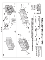
Step 1
1A. Installing the Seat
Slide the Seat (38) onto the Sliding Tube (2). Attach the Rubber Pad (34) onto the underside of
the Sliding Tube (2) with two Socket Phillips Screws (62). Tighten the hardware using the
Multi-Hex Tool with Phillips Screwdriver provided.
NOTE: The narrow edge of the Rubber Pad (34) should be pointing towards the Seat (38).
ASSEMBLY
Multi-Hex Tool with Phillips
Screwdriver 1PC
Tool:
Hardware:
(34) Rubber Pad
1 PC
(62) Socket Phillips
Screw
2 PCS

11
Step 2
2A. Installing the Rear Stabilizer
Attach the Rear Stabilizer (4) onto the underside of the Sliding Tube (2) with four Flat Washers
(55), four Spring Washers (52), and four Round Head Hex Bolts (81). Tighten the hardware using
the 6mm Allen Wrench provided.
ASSEMBLY
6mm Allen Wrench 1PC
Tool:
Hardware :
(55) Flat Washer
4 PCS
(81) Round Head
Hex Bolt
4 PCS
(52) Spring Washer
4 PCS

12
Step 3
3A. Installing the Front Stabilizer
Attach the Front Stabilizer (3) onto the Main Frame (1) with two Flat Washers (55), and two
Round Head Hex Bolts (65). Tighten the hardware using the 5 mm Allen Wrench provided.
Note: The wheel on the Left Front Stabilizer End Cap (31) should be facing forward when
installing the Front Stabilizer (3). See Fig. A.
ASSEMBLY
5mm Allen Wrench 1PC
Tool:
(55) Flat Washer
2 PCS
(65) Round Head
Hex Bolt
2 PCS
Hardware :
Fig. A

13
Step 4
4A. Installing the Central Stabilizer
Place a block of the packaging polyfoam in front of the Main Frame (1). Lift the Main Frame (1)
rest the machine on the polyfoam to help hold the frame up. Attach the Central Stabilizer (7) onto
the bottom of the Main Frame (1) with two Flat Washers (55) and two Round Head Hex Bolts
(81). Tighten the hardware using the 6mm Allen Wrench provided.
ASSEMBLY
6mm Allen Wrench 1PC
Tool:
(55) Flat Washer
2 PCS
(81) Round Head
Hex Bolt
2 PCS
Hardware :

14
Step 5
5A. Installing the Pedals
Attach one Hex Bolt (50) into the LOW bolt hole on the left side of the Main Frame (1). Tighten
using the Open Wrench provided.
Slide one Hex Bolt (50) through the center of the Pedal (12), then slide a Bushing (64) onto the
end of that Hex Bolt (50). Attach the group of parts to the TOP bolt hole on the left side of the Main
Frame (1). Tighten using the Open Wrench provided.
Repeat 5A for the left side.
NOTE: The heel of the Pedals (12) will rest on the lower Hex Bolt (50). See Fig. B
ASSEMBLY
Tool:
Open Wrench 1PC
Hardware:
(50) Hex Bolt
4 PCS
(64) Bushing
2 PCS
Fig. B

15
Step 6
6A. Installing the Seat Sliding Tube
Slide the Sliding Tube (2) into the Main Frame (1). Align the bolt holes shown in FIG. C, and insert
one Hex Bolt (46). Push the Hex Bolt (46) through the frame and attach one Round Head Hex
Bolt (57). Tighten using the 5mm Allen Wrench and 6mm Allen Wrench provided.
Insert the Safety Pin (47) to secure the Main Frame (1) and the Sliding Tube (2).
Secure the Main Frame (1) and Sliding Tube (2) with one Flat Washer (45) and one Round Knob
(44).
ASSEMBLY
5mm Allen Wrench
1PC
6mm Allen Wrench
1PC
Tool:
FIG. C
(46) Hex Bolt
1PC
(57) Round Head
Hex Bolt
1PC
(45) Flat Washer
1PC
(44) Round Knob
1PC
(47) Safety Pin
1PC
Hardware:

16
Step 7
7A. Installing the Console Batteries
Lifting up on the CLIP shown in FIG. D and gently pulling the Console (95) out. BE CAREFUL
when pulling the console out, there are three wires attached to the backside. Disconnect the wires
to make installing the batteries easy.
Using the Multi-Hex Tool with Phillips Screwdriver remove the SCREW from the BATTERY
COVER to open the Console (95). Place 4 AA batteries into the console with the positive and
negative poles as labeled.
Reattach the battery cover and replace the console back into the rowing machine. Make sure the
three wires are connected to the console before replacing the console. If any one of them is not
connected, the console will not function correctly.
Note: This product can only be powered by 4 AA batteries.
Note: Do not mix old and new batteries. Replace all the batteries at the same time.
ASSEMBLY
Multi-Hex Tool with Phillips
Screwdriver 1PC
Tool:
BATTERY
COVER
SCREW
95

17
USING THE CONSOLE
Power On: The console will turn on when the user
starts rowing or presses a button.
Power Off: The console will automatically turn off
after 20 minutes of inactivity.
Reset: Press and hold the STOP button for 3
seconds to reset the console.
Pause: Press the START button during a workout.
Start Workout: Press the START button for the
console to begin tracking your workout.
End Workout: Press the STOP button to end a
workout and show the workout results.
WORKOUT DISPLAY
STROKES: Will track the total number of strokes/pulls during the workout, up to a total of
9999.
o This display will shift between SPM and STROKES every 4 seconds.
o See the indicator arrow for the value currently being displayed.
CAL: Will track the number of calories burned during the workout, up to a value of 999.
o This is only an estimated value base on an average user.
TIME: Will track the total workout time, up to a maximum value of 99:59 minutes.
SPM: Will display the average number of strokes you are pulling in a minute based on the
current workout pace.
o This display will shift between SPM and STROKES every 4 seconds.
o See the indicator arrow for the value currently being displayed.
METERS: Will track your distance in meters, up to a maximum value of 9999 meters. The
console will end the workout when 9999 meters is reached.
SPLIT: Will display the average time it takes to travel 500 meters based on the current
workout pace.
WATTS: Will display the current workout effort in the form of Watts.
o The Watts value is dependent on the length of the pull, the pace of the workout, and
the resistance level.
o The resistance level control knob is wired to the console to track the effort of the
workout based on the resistance level set on the console.
o At the end of the workout, this section will show the MAX watt values reached during
the workout.
: The MyCloudFitness symbol turns on when the Bluetooth antenna is connected to the
APP.
o If the symbol is flashing, the connection to the app has not been established.
o If a connection cannot be made, shut down and restart the APP.
CONSOLE

18
SETTING WORKOUT GOALS
Press the GOALS button before starting a workout to set a METERS, TIME, CALORIES, or
STROKES GOAL.
Press the GOALS button until the desired GOAL option is flashing.
Use the UP and DOWN buttons to adjust the GOAL value.
Press the ENTER button to confirm the GOAL value.
Press the START button to begin the workout.
The console will beep 3 times when the GOAL is achieved.
ADJUSTING THE RESISTANCE LEVEL
Turn the knob clockwise to increase the resistance level of the workout.
Turn the knob Counter-clockwise to decrease the resistance level of the workout.
The console will adjust the distance per stroke, watt output, and calorie burn based on
resistance level setting.
CONSOLE
/