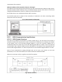
DataVideo PTC-200 User manual
- Category
- Gateways/controllers
- Type
- User manual

PTC-200
4K PTZ CAMERA
Instruction Manual

2
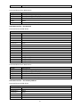
Table of Contents
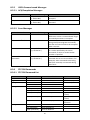
FCC COMPLIANCE STATEMENT ...................................................................... 4
WARNINGS AND PRECAUTIONS .................................................................... 4
WARRANTY ................................................................................................... 5
STANDARD WARRANTY ........................................................................................ 5
THREE YEAR WARRANTY ...................................................................................... 5
DISPOSAL ...................................................................................................... 6
1. PRODUCT OVERVIEW ............................................................................ 7
2. FEATURES ............................................................................................. 7
3. LOCATION AND FUNCTION OF PARTS ................................................... 8
4. REMOTE CONTROL AND ON-SCREEN MENU .......................................... 9
4.1 REMOTE CONTROL FUNCTIONS ................................................................. 9
4.2 ON-SCREEN MENU .............................................................................. 12
5. INSTRUCTION FOR INSTALLATION ....................................................... 20
5.1 STEP 1 – DIP SWITCH SETTING ............................................................... 20
5.2 STEP 2 – ONE END OF RETAINING WIRE ................................................... 20
5.3 STEP 3 – CEILING BRACKET (B) ............................................................... 21
5.4 STEP 4 – CEILING BRACKET (A) AND CAMERA ............................................ 22
5.5 STEP 5 – MOUNT CAMERA TO CEILING .................................................... 23
5.6 STEP 6 – SCREW TO FIX CAMERA ............................................................ 24
5.7 STEP 7 – CABLE CONNECTION ................................................................ 24
6. DIP SWITCH SETTINGS ......................................................................... 25
6.1 RS-422 ............................................................................................. 25
6.2 IRID .................................................................................................. 25
7. DVIP CONTROL PROTOCOL.................................................................. 26
7.1 DVIP SETUP ....................................................................................... 26
7.2 DVIP CONTROL OPERATION GUIDE ......................................................... 29
8. RS-422 CONTROL PROTOCOL .............................................................. 41
8.1 RS-422 PIN DESCRIPTIONS ................................................................... 41

3
8.2 RS-422 CONTROL OPERATION GUIDE ..................................................... 41
8.2.1 Overview of VISCA ....................................................................... 41
8.2.2 VISCA Communication Specifications ......................................... 42
8.2.3 VISCA Device Setting Command.................................................. 44
8.2.4 VISCA Command/ACK Protocol ................................................... 45
8.2.5 VISCA Camera-Issued Messages ................................................. 46
8.2.6 PTC-200 Commands .................................................................... 46
9. FIRMWARE UPDATE ............................................................................ 50
10. DIMENSIONS ................................................................................... 51
11. SPECIFICATIONS .............................................................................. 52
12. SERVICE & SUPPORT ....................................................................... 56
Disclaimer of Product and Services
The information offered in this instruction manual is intended as a guide only. At all times,
Datavideo Technologies will try to give correct, complete and suitable information. However,
Datavideo Technologies cannot exclude that some information in this manual, from time to time,
may not be correct or may be incomplete. This manual may contain typing errors, omissions or
incorrect information. Datavideo Technologies always recommend that you double check the
information in this document for accuracy before making any purchase decision or using the
product. Datavideo Technologies is not responsible for any omissions or errors, or for any
subsequent loss or damage caused by using the information contained within this manual. Further
advice on the content of this manual or on the product can be obtained by contacting your local
Datavideo Office or dealer.

4
FCC Compliance Statement
This device complies with part 15 of the FCC rules. Operation is subject to the following
two conditions:
(1) This device may not cause harmful interference, and
(2) This device must accept any interference received, including interference that
may cause undesired operation.
Warnings and Precautions
1. Read all of these warnings and save them for later reference.
2. Follow all warnings and instructions marked on this unit.
3. Unplug this unit from the wall outlet before cleaning. Do not use liquid or aerosol
cleaners. Use a damp cloth for cleaning.
4. Do not use this unit in or near water.
5. Do not place this unit on an unstable cart, stand, or table. The unit may fall,
causing serious damage.
6. Slots and openings on the cabinet top, back, and bottom are provided for
ventilation. To ensure safe and reliable operation of this unit, and to protect it
from overheating, do not block or cover these openings. Do not place this unit on
a bed, sofa, rug, or similar surface, as the ventilation openings on the bottom of
the cabinet will be blocked. This unit should never be placed near or over a heat
register or radiator. This unit should not be placed in a built-in installation unless
proper ventilation is provided.
7. This product should only be operated from the type of power source indicated on
the marking label of the AC adapter. If you are not sure of the type of power
available, consult your Datavideo dealer or your local power company.
8. Do not allow anything to rest on the power cord. Do not locate this unit where the
power cord will be walked on, rolled over, or otherwise stressed.
9. If an extension cord must be used with this unit, make sure that the total of the
ampere ratings on the products plugged into the extension cord do not exceed
the extension cord’s rating.
10. Make sure that the total amperes of all the units that are plugged into a single
wall outlet do not exceed 15 amperes.
11. Never push objects of any kind into this unit through the cabinet ventilation slots,
as they may touch dangerous voltage points or short out parts that could result in
risk of fire or electric shock. Never spill liquid of any kind onto or into this unit.
12. Except as specifically explained elsewhere in this manual, do not attempt to
service this product yourself. Opening or removing covers that are marked “Do
Not Remove” may expose you to dangerous voltage points or other risks, and will
void your warranty. Refer all service issues to qualified service personnel.
13. Unplug this product from the wall outlet and refer to qualified service personnel
under the following conditions:
a. When the power cord is damaged or frayed;
b. When liquid has spilled into the unit;
c. When the product has been exposed to rain or water;

5
d. When the product does not operate normally under normal operating
conditions. Adjust only those controls that are covered by the operating
instructions in this manual; improper adjustment of other controls may result
in damage to the unit and may often require extensive work by a qualified
technician to restore the unit to normal operation;
e. When the product has been dropped or the cabinet has been damaged;
f. When the product exhibits a distinct change in performance, indicating a need
for service.
Warranty
Standard Warranty
• Datavideo equipment are guaranteed against any manufacturing defects for one
year from the date of purchase.
• The original purchase invoice or other documentary evidence should be supplied at
the time of any request for repair under warranty.
• The product warranty period beings on the purchase date. If the purchase date is
unknown, the product warranty period begins on the thirtieth day after shipment
from a Datavideo office.
• Damage caused by accident, misuse, unauthorized repairs, sand, grit or water is not
covered under warranty.
• Viruses and malware infections on the computer systems are not covered under
warranty.
• Any errors that are caused by unauthorized third-party software installations,
which are not required by our computer systems, are not covered under warranty.
• All mail or transportation costs including insurance are at the expense of the owner.
• All other claims of any nature are not covered.
• Cables and batteries are not covered under warranty.
• Warranty only valid in the country or region of purchase.
• Your statutory rights are not affected.
Three Year Warranty
• All Datavideo products purchased after July 1st, 2017 are
qualified for a free two years extension to the standard
warranty, providing the product is registered with
Datavideo within 30 days of purchase.
• Certain parts with limited lifetime expectancy such as LCD panels, DVD drives, Hard
Drive, Solid State Drive, SD Card, USB Thumb Drive, Lighting, Camera module, PCIe
Card are covered for 1 year.
• The three-year warranty must be registered on Datavideo's official website or with
your local Datavideo office or one of its authorized distributors within 30 days of
purchase.

6
Disposal
For EU Customers only - WEEE Marking
This symbol on the product or on its packaging indicates that this
product must not be disposed of with your other household
waste. Instead, it is your responsibility to dispose of your waste
equipment by handing it over to a designated collection point for
the recycling of waste electrical and electronic equipment. The
separate collection and recycling of your waste equipment at the
time of disposal will help to conserve natural resources and
ensure that it is recycled in a manner that protects human health
and the environment. For more information about where you can drop off your waste
equipment for recycling, please contact your local city office, your household waste
disposal service or the shop where you purchased the product.
CE Marking is the symbol as shown on the left of this page. The
letters "CE" are the abbreviation of French phrase "Conformité
Européene" which literally means "European Conformity". The
term initially used was "EC Mark" and it was officially replaced by
"CE Marking" in the Directive 93/68/EEC in 1993. "CE Marking" is
now used in all EU official documents.

7
1. Product Overview
The PTC-200 Video Camera is a 4K UHD PTZ camera that can be mounted on a
wall, ceiling, floor, or a tabletop. The camera captures up to 4K (3,840 x 2,160,
UHD) video at 2160p29.97/25 resolution, and features wide dynamic range
with backlight compensation. The camera features a motorized 12x optical
zoom capability, and its image mirror and image rotation functions allow you
to electronically adjust the image and deliver a correctly oriented image.
50 programmable presets including pan, tilt, and zoom positions, allow the
camera to quickly move between predetermined camera positions using the
remote, or an available PTZ controller.
For multi-camera shoots, the built-in tally light can identify active camera. The
camera features a built-in IR cut filter in the image path for low light shooting,
and then returns for daytime shooting. Moreover, PTC-200 supports real time
position report on a per frame basis; this will be helpful to virtual studio
application. The camera supports Sony VISCA protocol for PTZ control using
RS-422 interface over the unit's RJ-45 port.
2. Features
• HD Resolution: 1/2.3" High Definition 8.93 M Pixels progressive CMOS
sensor
• 12x optical zoom (f = 3.9 mm to 46.8 mm)
• High definition formats supported:
- 4K (3,840 x 2,160, UHD): 2160p/29.97, 2160p/25
- HD: 1080/59.94p, 1080/50p, 1080/59.94i, 1080/50i, 720/59.94p,
720/50p
• Digital Noise Reduction Function (DNR) to reduce the noise and enable
clearer image under low light conditions.
• Position coordinates report in real time per frame.
• Video Output: 3G-SDI + HDMI synchronously.
• Tally LED Design (IR Controller / RS-422 / DVIP Operation)
• Supports VISCA Protocol Keyboard
• Supports DVIP Control Protocol

8
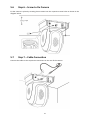
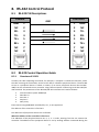
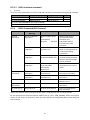
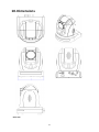
3. Location and Function of Parts
Front of Camera
1
Lens
Built-in 1/2.3” 8.93M Pixel CMOS HD color
camera with white balance control, backlight
compensation settings, automatic gain settings
and etc.
2
Tally LED
Tally lamp lights up when tally signal has been
transmitted to the tally signal box.
3
Sensor for Remote Control
Remote controller receiver
Rear of Camera
1
DIP Switch SW2
DIP switch for IRID setting
2
RS422 Communication Port
Remote control of camera via RJ-45 interface
3
3G-SDI OUT
Video signal output
4
HDMI OUT
Video signal output
5
DVIP Communication Port
6
Power Input
DC 12V Input
7
USB Port
F/W Upgrade Only
Bottom of Camera
1
Tripod Screw Hole
2
DIP Switch SW1
Camera ID setting for camera cascading
3
Screw Hole
Screw holes for ceiling bracket mounting

9
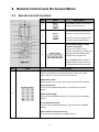
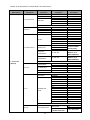
4. Remote Control and On-Screen Menu
4.1 Remote Control Functions
No
Item
Description
1
Reset
Press RESET button to return the
camera lens to the front.
2
Group
Use the No. bottom & the group
bottom to select the group scan.
Press any of the No. buttons 1~8
and then press GROUP button.
3
Camera Select
Select CAM1-CAM4 in a multi-
camera environment
Assign an ID number to the
camera intended for operation by
adjusting the IRID (SW2) switch
located at the camera rear.
Press CAMERA SELECT (CAM 1~
CAM4) buttons set previously to
navigate between four cameras.
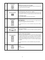
No.
Item
Description
4
Position Setting
Various combinations of settings (position, zoom, focus, gain
control and iris control) can be saved to presets.
Adjust Preset Point
Adjust position, zoom, focus, gain control and iris of the camera.
Set up Preset Point
Press any of the POSITION buttons 1~50 and then press SET
button.
Recall saved settings
Press any of the POSITION buttons 1~50 and then press PRESET
button.
Set up Group Scan mode
Press any of the POSITION buttons 1~8 and then press GROUP
button.
Return Camera Lens back to Front
Press number 0 and then press PRESET button.

10
5
Focus Setup
Manually focus camera lens on a subject
Press either (F) FAR button or (N) NEAR button to manually focus
the camera lens onto the subject.
6
Auto Focus Control
Automatically focus camera lens on a subject
Press A/ FOCUS button. Camera lens will be automatically focused
on the subject such that it is positioned at the center of the screen.
Exit Sub-Menu Option
Press A/ FOCUS button to exit sub-menu option.
7
Gain Control
Adjust Brightness
Press GAIN+ button to increase the brightness or GAIN- button to
decrease the brightness of the environment.
To cancel the function or return to default setup, press A/ GAIN
button.
8
P/T Speed
Adjust Pan/ Tilt Speed
Press SPEED + / - button to switch to different speeds (up/down).
9
Auto Iris Control
Make the subject appear brighter
Adjust the iris opening (aperture), to control the amount of light
coming through the lens (i.e. the "exposure"). Press IRIS+ button to
enlarge the iris opening to allow more light to come in so that the
subject appears brighter and press IRIS- button to shrink the iris
opening to allow less light to come in so that the subject appears
less bright.
To cancel the function or return to default setup, press A/IRIS
button.
10
ENTER
ENTER
Menu ENTER key.

11
11
Direction Arrows
Change camera direction
Press arrow buttons to change the direction of the camera head.
Stop Preset Point Auto Scan mode
Press any of the DIRECTION buttons.
Select Menu Option
Press UP or DOWN button to select the menu option.
Adjust P/T Speed
Press UP or DOWN button to adjust the PAN/TILT Speed.
Enter Sub-Menu Option
Press ENTER button to enter sub- menu option.
Adjust Setup Value
Press LEFT or RIGHT button to adjust the value.
12
MENU Button
Enter or Exit Camera Menu
13
Zoom In/Out Buttons
Zoom
Press either (T) TELE button to zoom in on the subject such that it
appears to be close to the camera or (W) WIDE button to zoom out
from the subject such that it appears to be far away from the
camera.
14
Zoom Speed Button
(4 speed selection)
Adjust Zoom In/Out Speed
Press this button to switch to different speeds (The Highest~ The
Lowest).
15
Power Button
Switch Remote Controller ON/OFF

12
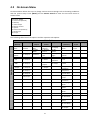
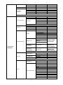
4.2 On-Screen Menu
On-Screen Menu allows the user to change various camera settings such as shooting conditions
and the system setup. Press [Menu] on the remote control to enter the on-screen menu as
shown below.
The following table lists all the options and the respective sub-options.
Main Options
Camera Set
(Normal)
Memory
Video
Output
Remote
Control
System
Camera Set
(Advance)
Reset
P/T/Z
Escape
Sub-Options
1. Camera
Name
1. Preset
Position
1. Selection
Way
1. PAN/TITL
Reverse
1. Display
1. Camera
Name
7. Reset
P/T/Z
2. Mirror
2.Group-1
2. Video
Mode
2. Remote
Source
2. Set
Motor
2. Mirror
3. White
Balance
3. Group-2
3. Pattern
3. Set RS-
422
3. Tally
Light
3. White
Balance
4. Focus
4. Group-3
4. Escape
4. Set DVIP
4. Reset All
4. Focus
5. Iris
5. Group-4
5. Set IR
5. Update
Software
5. Iris
6. AGC
6. Group-5
6. PTZ Info.
Output
6. Escape
6. AGC
7. Escape
7. Group-6
7. Escape
7. Fog
Correction
8. Group-7
8. Aperture
9. Group-8
9. Color Gain
10. Escape
10. Exposure
Comp.
11. Backlight
Correction
12. Day/Night
Mode
13. Shutter
Speed
14. Gamma
Mode
15. HR Mode
16. WD Mode
17. Digital
Zoom
18. Low Delay
19. Escape
On-Screen MENU
1: Camera Set (Normal)
2: Memory
3: Video Output
4: Remote Control
5: System
6: Camera Set (Advance)
7: Reset P/T/Z
8: Escape

13
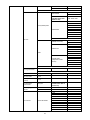
Details of all OSD options are described in the table below.
First Level
Main Options
Second Level
Sub-Options
Third Level
Parameters
Fourth Level
Parameters
Sub-Option
Descriptions
1. Camera Set
(Normal)
1. Camera Name
NAME
DISPLAY SW
ON/OFF
POSITION
LOWER LEFT
UPPER LEFT
LOWER RIGHT
UPPER RIGHT
ESCAPE
2. Mirror
H+V
V
H
OFF
3. White Balance
MODE
ATW/AWB(AUTO)
AWC (ONE PUSH)
MWB (MANUAL)
3200K (INDOOR)
5600K (OUTDOOR)
4200K (FLUO)
SMART ATW
SMART1
(Enabled in AWB
(AUTO) mode)
SMART2
SMART3
MWB RED
COMPONENT
0~128~255
(Enabled when
MODE is set to
MWB (MANUAL))
MWB BLUE
COMPONENT
0~128~255
(Enabled when
MODE is set to
MWB (MANUAL))
ESCAPE
4. Focus
FOCUS MODE
AUTO
MANUAL
AF SENSITIVITY
LOW
NORMAL
FOCUS SPEED
1~8
ESCAPE
5. Iris
IRIS MODE
AUTO IRIS
MANUAL
MANUAL IRIS
LEVEL
F1.8
F2.0
F2.4
F2.8
F3.4
F4
F4.8
F5.6
F6.8
F8
F9.6
F11
F14
CLOSE
ESCAPE
6. AGC
DAY (COLOR) AGC
AGC MODE
OFF
ON
MANUAL GAIN
(Enabled when AGC
0 dB ~ GAIN LIMIT

14
Mode is OFF)
GAIN LIMIT
9 dB
12 dB
15 dB
18 dB
21 dB
24 dB
27 dB
30 dB
33 dB
ESCAPE
DNR
DNR (AT AGC ON)
ON
OFF
DNR LEVEL
0
1
2
3
4
5
3D NR LEVEL
(Adjusted in DNR
LEVEL)
0
1
2
3
4
5
ESCAPE
ESCAPE
7. Escape
2. Memory
1. Preset Position
1-50 Preset
Positions
1. P/T Speed
2. Focus
tuvw
3. Iris
tuvw
4. Gain
pqrstuvw
5. Shutter
1/1
1/2
1/3
1/6
1/12
1/25
1/50
1/75
1/100
1/120
1/150
1/215
1/300
1/425
1/600
1/1000
1/1250
6. WB Mode
AWB
MWB
7. WB R-Gain
0-127
8. WB B-Gain
0-127
9. Escape
51. Escape
Group-1-8
----/OF_SPD--_W---
_NEXT
1. Preset No.
2. Item ON/OFF
3. Speed Limit

15
4. Waiting Time
5. Next Position
6. Escape
10. Escape
3. Video Output
1. Selection Way
BY MENU
BY SWITCH
2. Video Mode
1080i60
1080i50
720p60
720p50
1080p60
1080p50
2160p30
2160p25
3. Pattern
OFF
COLOR BAR
4. Escape
4. Remote
Control
1. PAN/TILT
Reverse
Off
P
T
P+T
2. Remote Source
RS-422, SW
(Configurable using
DIP switch bit 4
ONLY)
DVIP, SW
3. Set RS-422
CAMERA ID MODE
BY MENU
BY SWITCH
CAMERA ID
1~7
RS-422 BAUD RATE
9600
19200
38400
115200
ESCAPE
4. Set DVIP
DVIP BAUD RATE
9600
19200
38400
57600
115200
ESCAPE
5. Set IR
IR GROUP ID
CAM1~4
(Configurable using
DIP switch bit 9/10
ONLY)
ESCAPE
6. PTZ INFO.
Output
ON/OFF
7. Escape
5. System
1. Display
PTZ OSD
PAN OSD
ON/OFF
TILT OSD
ON/OFF
ZOOM OSD
ON/OFF
ESCAPE
DEBUG OSD
DEBUG IR OSD
ON/OFF
DEBUG CAM. OSD
ON/OFF
DEBUG RS-422 OSD
ON/OFF

16
DEBUG DVIP OSD
ON/OFF
DEBUG M_CTL OSD
ON/OFF
DEBUG REG OSD
ON/OFF
DEBUG FRAME NO
ON/OFF
PWR ON CAM TEST
ON/OFF
ESCAPE
Camera Status
OSD
ON/OFF
Escape
2. Set Motor
P/T Acceleration
FAST
MIDDLE
SLOW
P/T Speed
Normal
X2, Surveillance
PAN Torque ADJ.
+5
+4
+3
+2
+1
Low
TILT Torque ADJ.
+5
+4
+3
+2
+1
Low
PAN Offset ADJ.
+5.4
+4.5
+3.6
+2.7
+1.8
+0.9
+0.0
-0.9
-1.8
-2.7
-3.6
-4.5
-5.4
Tilt Offset ADJ.
+6.3
+5.4
+4.5
+3.6
+2.7
+1.8
+0.9
+0.0
-0.9
-1.8
-2.7
-3.6
-4.5
-5.4
-6.3
Escape
3. Tally Light
RED/GREEN
GREEN

17
RED
OFF
4. Reset All
YES/NO
5. Update
Software
SW VERSION
ESCAPE
MB CPU
V00.28a
MCTL CPU
V01.00
UPDATE ALL
YES/NO
ESCAPE
6. Escape
6. Camera Set
(ADVANCE)
1. Camera Name
NAME
DISPLAY SW
ON/OFF
POSITION
UPPER LEFT
LOWER RIGHT
UPPER RIGHT
LOWER LEFT
ESCAPE
2. Mirror
H+V
V
H
OFF
3. White Balance
MODE
ATW/AWB(AUTO)
AWC (ONE PUSH)
MWB (MANUAL)
3200K (INDOOR)
5600K (OUTDOOR)
4200K (FLUO)
SMART ATW
SMART1
(Enabled in AWB
(AUTO) mode)
SMART2
SMART3
MWB RED
COMPONENT
0~128~255
(Enabled when
MODE is set to
MWB (MANUAL))
MWB BLUE
COMPONENT
0~128~255
(Enabled when
MODE is set to
MWB (MANUAL))
ESCAPE
4. Focus
FOCUS MODE
AUTO
MANUAL
AF SENSITIVITY
LOW
NORMAL
FOCUS SPEED
1~8
ESCAPE
5. Iris
IRIS MODE
AUTO
MANUAL
Manual IRIS LEVEL
F1.8
F2.0
F2.4
F2.8
F3.4
F4
F4.8
F5.6
F6.8
F8
F9.6
F11

18
F14
CLOSE
ESCAPE
6. AGC
DAY (COLOR) AGC
AGC MODE
ON
OFF
MANUAL GAIN
(Enabled when AGC
Mode is OFF)
0dB~GAIN LIMIT
GAIN LIMIT
9 dB
12 dB
15 dB
18 dB
21 dB
24 dB
27 dB
30 dB
33 dB
ESCAPE
DNR
DNR(AT AGC ON)
ON
OFF
DNR LEVEL
0
1
2
3
4
5
3D NR LEVEL
(Adjusted in DNR
LEVEL)
0
1
2
3
4
5
ESCAPE
7. Fog Correction
FOG CORRECTION
OFF/ON
ESCAPE
8. Aperture
0~15
9. Color Gain
0~14
10. Exposure
Comp.
0~14
11. Backlight
Correction
OFF/ON
(This option is
enabled after AGC is
turned on)
12. Day/Night
Mode
B/W
COLOR
13. Shutter
SHUTTER SPEED
1/30
1/60
1/90
1/100
1/125
1/180
1/250
1/350
1/500
1/725
1/1000

19
1/1500
ESCAPE
14. Gamma Mode
STANDARD
MODE1 (WD OFF)
MODE2 (WD OFF)
15. HR Mode
ON/OFF
16. WD Mode
VE/OFF
17. Digital Zoom
ON/OFF
18. Low Delay
ON/SET
19. Escape
7. Reset P/T/Z
YES/NO
8. Escape

20
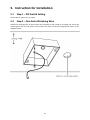
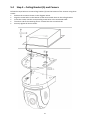
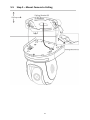
5. Instruction for Installation
5.1 Step 1 – DIP Switch Setting
Set the Mirror option to H+V mode.
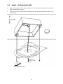
5.2 Step 2 – One End of Retaining Wire
Attach the retaining wire to the junction box mounted on the ceiling by screwing one end of the
retaining wire into a screw hole in the junction box with a screw (not supplied) as shown in the
diagram below.
Page is loading ...
Page is loading ...
Page is loading ...
Page is loading ...
Page is loading ...
Page is loading ...
Page is loading ...
Page is loading ...
Page is loading ...
Page is loading ...
Page is loading ...
Page is loading ...
Page is loading ...
Page is loading ...
Page is loading ...
Page is loading ...
Page is loading ...
Page is loading ...
Page is loading ...
Page is loading ...
Page is loading ...
Page is loading ...
Page is loading ...
Page is loading ...
Page is loading ...
Page is loading ...
Page is loading ...
Page is loading ...
Page is loading ...
Page is loading ...
Page is loading ...
Page is loading ...
Page is loading ...
Page is loading ...
Page is loading ...
Page is loading ...
-
 1
1
-
 2
2
-
 3
3
-
 4
4
-
 5
5
-
 6
6
-
 7
7
-
 8
8
-
 9
9
-
 10
10
-
 11
11
-
 12
12
-
 13
13
-
 14
14
-
 15
15
-
 16
16
-
 17
17
-
 18
18
-
 19
19
-
 20
20
-
 21
21
-
 22
22
-
 23
23
-
 24
24
-
 25
25
-
 26
26
-
 27
27
-
 28
28
-
 29
29
-
 30
30
-
 31
31
-
 32
32
-
 33
33
-
 34
34
-
 35
35
-
 36
36
-
 37
37
-
 38
38
-
 39
39
-
 40
40
-
 41
41
-
 42
42
-
 43
43
-
 44
44
-
 45
45
-
 46
46
-
 47
47
-
 48
48
-
 49
49
-
 50
50
-
 51
51
-
 52
52
-
 53
53
-
 54
54
-
 55
55
-
 56
56


DataVideo PTC-200 User manual
- Category
- Gateways/controllers
- Type
- User manual
Ask a question and I''ll find the answer in the document
Finding information in a document is now easier with AI
Related papers
Other documents
-
Sony EVI-HD1 User manual
-
-
-
 Telycam TLC-1000-U2S User manual
-
Sony SRG-360SHE User guide
-
-
 Minrray UV820 User manual
-
 Telycam TLC-1000-U2-10-S Owner's manual
-
Seeed 24GHz mmWave Sensor - Human Static Presence Module Lite - human presence, FMCW, Configurable Underlying Parameter, Arduino User manual
-
Marshall Electronics CV610-U3 User manual


