Sioux Chief Elbow Installation guide

Type
Installation guide
Supply Drainage Support Specialties
Installation Manual
Tubing
Fitting Systems
Tools & Accessories
Installation Guidelines
Certications & Listings
Warranty
Installation Manual
Introduction
This manual covers the specications and installation
guidelines for Sioux Chief's full line of PowerPEX® tube
and PEX tting systems. The manual describes all of
the various ASTM PEX product standards, and how
Sioux Chief's PowerPEX products are installed per those
standards.
All product or system installations shall adhere to the
procedures and guidelines within. Nothing within is
intended to establish a warranty beyond Sioux Chief's
expressed warranty. Check with all local codes prior to
installation.
www.siouxchief.com 2www.siouxchief.com 2
TABLE OF CONTENTS
Tubing
1
2.3 PEX Tubing Product Standards & Code Compliance pg 7-8
2.1 Sioux Chief PowerPEX Tube Types,
Availability & System Compliance pg 5
1.1 Explaining PEX Tube pg 4
2.2 PowerPEX Markings / Print Stream pg 6
2.4 Material Benets & Properties pg 9
PowerPEX Tubing
2
3.3 Special Considerations for Polymer Fittings pg 16
3.1 ASTM F1807 | F2159 Crimp Installations pg 13-14
3.2 ASTM F1960 Expansion Ring Installations pg 15
Fitting Systems
3
4.3 ASTM F1960 Expansion Tools pg 19
4.1 PEX Accessories, Tools, Gauging & Tips pg 17
4.2 ASTM F1807 | F2159 Crimp Tool
Repair & Calibration pg 18
Tools & Accessories
4
5.3 Manifold Plumbing pg 23-24
5.5 Avoiding Common Problems pg 31-32
5.1 Hybrid Systems/Combination Install pg 20-21
5.2 System Installation Options pg 22
5.4 Tubing Installation Requirements & Limitations pg 25-30
Installation Guidelines
5
Certications & Listings
6
What is PowerPEX?
Sioux Chief offers the industry's leading PEX systems. Sioux Chief's PEX offering is the most complete in the plumbing
industry. All tting and tube solutions carry a 25-year warranty, mixed or matched. Sioux Chief does not limit its warranty
on tube or ttings based on matching system connections like some other PEX tubing suppliers.
PowerPEX gives contractors the ability to choose the right tube or tting connection for each application, layout or contractor
comfort level. We call this Fitting Freedom.
6.0 PowerPEX Certications pg 34
7.0 Sioux Chief Warranty pg 36
Warranty & Terms of Use
7
PEX tubing is economical and cost-effective.
Manufacturing PEX tubing consumes less energy
than manufacturing metal tubing. It is lighter
weight, which helps to lower transportation costs
and is easier to handle for the installer. PEX can be
coiled, which reduces overall storage space.
PEX is exible, so it can be installed in ways that
reduce the total number of ttings needed, which
minimizes the potential for leaks. It can help
reduce system noise by eliminating sharp bends
and reduces hot water wait times when used in
manifold systems.
www.siouxchief.com 4www.siouxchief.com 4
1
PEX Tubing
PEX is cross-linked polyethylene. Through one of several
processes, links between polyethylene molecules are
formed to create bridges (thus the term “cross-linked").
This resulting material is more durable under temperature
extremes, chemical attack, and better resists creep
deformation, making PEX an excellent material for
potable water and other applications. The physical
properties of PEX tubing make it ideal for use with
various mechanical connection systems.
There are three primary methods for producing PEX tubing:
PEX-A Engel” or Peroxide Method.
Peroxide is added to the base resin. As the tubing is
produced, cross-linking takes place due to pressure
and high temperature.
PEX-B “Silane” Method.
Silane is grafted to the backbone of the polyethylene.
The grafted compound is combined with a catalyst
through the Sioplas or Monosil methods. Extruded
tube is exposed to steam or hot water to complete
the cross-linking reaction. The resultant link is three-
dimensional in nature whereby the bunch-like bond
is not unlike a trellis.
PEX-C Electron Beam Method.
Very high-energy radiation is used to initiate molecular
cross-linking in specialty high-density polyethylene.
Tube is extruded (generally as HDPE), routed through
an E-Beam facility and rotated under a beam in the
accelerator where it is dosed with a specic amount
of radiation to release the hydrogen atoms and cause
polymer chains to link to the open carbon sites.
The resultant link is planar in nature and a carbon to
carbon bond.
PEX Tubing Applications
PEX tubing is ideally suited for potable water plumbing
applications. It is exible, making it easy to install
and service. It is also able to withstand the high and
low temperatures found in plumbing and heating
applications and is highly resistant to chemicals found
in the plumbing environment.
Special system component consideration and elimination
of ferrous components must be made for radiant or snow
melt systems when using non-barrier tubing.
Check with local codes and applicable requirements.
PEX Tubing
General Information
Common Application Types:
Water service
Potable water plumbing
Hydronic / radiant cooling
Hydronic / radiant heating*
Snow / ice melting systems*
Turf conditioning systems
Permafrost systems
Water reclamation
Fire suppression**
Mixed (plumbing + re suppression, etc.)
No Lead systems
Geothermal
Dezincication resistant systems
5 www.siouxchief.com
2
Sioux Chief PowerPEX - PEX-B
Sioux Chief PEX-B tube is made using the Sioplas method
described earlier. This involves a 2 component extrusion
with the base material comprising 95% of the end
product and the catalyst to start the reaction accounting
for the remaining 5%. The reaction begins at extrusion
and is accelerated by curing at elevated temperatures
and with moisture exposure.
Sioux Chief PowerPEX - PEX-A
Sioux Chief PEX-A tube is made using the Engel process
described earlier where heated extrusion of a specialty
PE resin containing a high concentration of organic
peroxide creates PEX. As the peroxide decomposes,
bonds on the polyethylene chains are formed.
TUBE
SIZE STANDARD DESIGNATION CODE
& TUBE TYPE
Non-Barrier Tube
1/2" ASTM F876/F877 5306 (PEX-B) 3006 (PEX-A)
3/4" ASTM F876/F877 5306 (PEX-B) 3006 (PEX-A)
1" ASTM F876/F877 5306 (PEX-B) 3006 (PEX-A)
1-1/4" ASTM F876/F877 5306 (PEX-B) 3006 (PEX-A)
1-1/2" ASTM F876/F877 5306 (PEX-B) 3006 (PEX-A)
2" ASTM F876/F877 5306 (PEX-B) 3006 (PEX-A)
Oxygen Barrier Tube
1/2" ASTM F876/F877 5006 (PEX-B) 3006 (PEX-A)
3/4" ASTM F876/F877 5006 (PEX-B) 3006 (PEX-A)
1" ASTM F876/F877 5006 (PEX-B) 3006 (PEX-A)
PowerPEX Tubing
PowerPEX Tube & Fitting System Compatibility
38"½" ¾" 1" 1¼" 1½" 2"
ASTM F1807
ASTM F2159
ASTM F1960
ASTM F3347
ASSE 1061
PowerPEX Fitting Size Availability
PowerPEX® Tubing
Flexible, Durable, Quality Tubing – Made in America
PEX-B
TUBING
PEX-A
TUBING
BARRIER
PEX-B
BARRIER
PEX-B
PE-RT
TUBING
ASTM F1807
Crimp PEX
ASTM F2159
Crimp PEX
ASTM F1960
Grip PEX
ASSE 1061
PDQ Push Fit
ASTM F3347 / F3348
Compression Sleeve PEX
www.siouxchief.com 6
PRINTED MARKINGS ON TUBING
1Company Name
2Product Name
3Standard Dimensional Ratio For Fitting Size Acceptance
4Tubing Size
5National Sanitation Foundation Mark for Toxicity and/or Performance Certication
6IAPMO Listing (Model Plumbing Code Body)
7CSA Listing & Canadian Certication
8Applicable Standard Certications for Performance & Manufacturers
9Compatible Fitting Systems Standards
10 Chlorine & UV Resistance Per Standard
11 Oxygen Barrier Specication (if applicable)
12 Pressure & Temperature Rating
13 Country of Origin
14 Date, Time, & Manufacturer’s Line Tracking Number
Sioux Chief PowerPEX Tube Markings
1
3
2
4
5
6
7
9
10
11
12
8
PowerPEX Identification & Testing 2.2
13
14
7 www.siouxchief.com
PEX 5 3 0 6
Material
Chlorine Resistance
5 = (100% use at 140°F)
Minimum UV Resistance
3 = (6 months)
Hydrostatic Design Stress (HDS) at 23°C
06 = (06 x 100 psi or 630 psi)
PEX Tube Designation Code Example: 5306
Sioux Chief PowerPEX Production Tests and Continuous Compliance Tests
TEST STANDARD FREQUENCY
Density ASTM D1505 Each Tubing Run
Hydrostatic Sustained Pressure ASTM D1598 Random Continuous Samples
Hydrostatic Burst Pressure ASTM D1599 Each Tubing Run
Environmental Stress Cracking ASTM F876 Annually
UV Inhibition ASTM F2657 During Certication
Degree of Cross-linking ASTM D2765 Each Tubing Run
Stabilizer Functionality ASTM D1598 During Certication
Oxidative Stability ASTM F2023 During Certication
Bent Tube Sustained Pressure ASTM D1598 Annually
Excessive Temp + Pressure Capability ASTM D1598 Each Random Continuous Samples
Melt Flow Index ASTM D1238 Each Receipt
Ongoing Dimensional Checks (OD, ID, Wall Thickness, Homogeneity, Etc.) ASTM F876/877 Continuous
Ongoing Dimensional Checks - Fittings (Copper, Brass, Plastic) ASTM FITTING STANDARD Each Run
Rockwell Tests for Copper Crimp Rings ASTM F1807 Each Run
Alloy Material Test (X-Ray Florescence Analyzer) ASTM FITTING STANDARD Each Receipt
Certicate of Resin Compliance PER MSDS SHEET Each Receipt
Crush Test (for PPSU Fittings) ASTM F2159 Random Continuous Samples
Integer 1: (chlorine resistance) PER
ASTM F2023
0 = Not tested for Chlorine resistance
1 = 25% use @ 140ºF
& 75% use @ 73ºF
3 = 50% use @ 140ºF
& 50% use @ 73ºF
5 = 100% use @ 140ºF
Integer 2: (min. UV resistance) PER
ASTM F2657
0 = Not tested for UV exposure
1 = Max. exposure of 1 month
2 = Max. exposure of 3 months
3 = Max. exposure of 6 months
Integer 3&4:
(HDS @ 73ºF) × 100 psi.
06 = 630 psi.
PEX Tube: Chlorine Resistance and UV Inhibition
2.3 PEX Tubing Product Standards & Code Compliance
Tubing Product Standards
ASTM F876: Standard Specication for Cross-linked
Polyethylene (PEX) Tubing
ASTM F877: Standard Specication for Cross-linked
Polyethylene (PEX) Hot & Cold-Water Distribution Systems
CSA B137.5: Cross-linked Polyethylene (PEX) Tubing
Systems for Pressure Applications
ASTM F2623: Standard Specication for Polyethylene of
Raised Temperature (PE-RT) SDR9 Tubing
ASTM F2769: Standard Specication for Polyethylene of
Raised Temperature (PE-RT) Plastic Hot and Cold Water
Tubing and Distribution Systems
ASTM E84 & CAN/ULC S102: Standard Test Method for
Surface Burning Characteristics of Building Materials
ASTM E119 & CAN/ULC S101: Standard Test Methods
for Fire Tests of Building Construction and Materials
ANSI/AWWA C904: Cross-Linked Polyethylene (PEX)
Pressure Tubing, ½ In. (13 mm) Through 3 In. (76 mm),
for Water Service
Code Acceptance
Tubing Code Compliance Below is a list of commonly
referenced and recognized plumbing model codes, which
recognize PEX tubing installation and reference standards
for application and installation compliance. Individual
standards can be referenced in section 6.
Area / Region Many cities, states, counties or other
jurisdictions may employ and determine what standards,
specications, and plumbing/heating practices are
satisfactory. Check with all local and state codes prior to
any installation.
International
Plumbing Code International
Residential Code
Tubing Product Standards & Code Compliance 2.3
Sioux Chief utilizes the most state-of-the-art
extrusion equipment and facilities to manufacture,
inspect, stock, ship and service PEX tubing to the
plumbing and radiant heating industries.
Uniform
Plumbing Code
National Sanitation
Foundation
9 www.siouxchief.com
Secondary Manifolds
Primary Manifolds
Material Benets of PEX Tubing
Corrosion Resistant
Smooth inner walls inhibit mineral build up and scaling.
Resists pitting or stress-corrosion more than other types
of tube. PEX is also more resistant to the harmful effects
of chemicals such as chlorine.
Quiet
Flow characteristics are increased and system noise is
decreased when compared to metal tubing systems.
Freeze Resistant
While it is always recommended to follow code
requirements and common practices to protect from
freezing, PEX tubing can expand and contract more easily
(often without damage) than copper and CPVC tubing.
Reduced Turbulence / Increased Flow
The smooth interior wall of the tube reduces turbulence
during water demand thereby increasing the overall ow
characteristics to the xture being supplied.
Thermal Conductivity
Lower heat transfer compared to metal tube, saving
energy and money.
Installation Flexibility
PEX tube bends easily and can be plumbed around
building members or through oors/walls. Using exible
tubing means fewer ttings, fewer brackets, fewer joints
behind the wall, fewer hours on the job, and fewer
potential leaks.
Installation Tips
When servicing a line, Sioux
Chief recommends using valved
manifolds whenever possible.
Primary manifolds should always
be valved.
Manifolds can always be coupled
together with other manifolds
and PEX tube to achieve the
desired number of branches.
2.4 Material Benefits & Properties
Do NOT recirculate back through
the manifold branch. Doing so will
void the manifold warranty.
IMPORTANT
www.siouxchief.com 10
Material Properties of PEX Tubing
Water Temperature + Water Pressure
PEX tubing shall not be used in applications where
temperature and pressure ratings are not regulated or
are known to evidence exposures beyond the tested and
certied limit of the tube.
TEMPERATURE HYDROSTATIC
PSI (MAX)
OPERATING
PSI WATER
73.4° F / 23° C 630 160
180° F / 82.2° C 400 100
200° F / 93.3° C 315 80
Tube Operating Pressure / Temperatures
Flow Characteristics
GPM
1/2" PRESSURE
DROP @ 60ºF
(PSI/100FT)
VELOCITY
(F T/SEC)
3/4" PRESSURE
DROP @ 60ºF
(PSI/ ) 100FT
VELOCITY
(F T/SEC)
1" PRESSURE
DROP @ 60ºF
(PSI/100FT)
VELOCITY
(F T/SEC)
11.8 1.7 1.2 0.9 .4 0.5
25.9 3.5 2.4 1.8 .7 1.0
312.1 5.2 4.0 2.7 1.2 1.6
420.1 75.7 3.5 1.8 2.1
58.1 4.4 2.5 2.7
610.7 5.3 3.2 3.2
713.5 6.2 4.1 3.7
87.1 5.0 4.3
96.0 4.8
*See Section 5.4 for Tubing Installation Requirements & Limitations.
Or, specic manufacturer's instructions for continuous pipe support
systems for large diameter horizontal arterial water mains.
*Without bend support. See Section 5.4 for additional information.
Minimum Bend Radius*
TUBE SIZE (CTS) MIN. BEND RADIUS
1/2" 3.75"
3/4" 5.25"
1" 6.75"
1-1/4" 8.25"
1-1/2" 9.75"
2" 12.75"
Support + Spacing
TUBE SIZE HORIZONTAL
SUPPORT SPACING
VERTICAL
SUPPORT SPACING
1/2" 32"
Once per oor penetration
at oor level.
Once at midpoint of oor
expanse or every 48"
3/4" 32"
1" 32"
1-1/4" 32"*
1-1/2" 32"*
2" 32"*
Material Benefits & Properties 2.4
Bending Stress on Polymer Fittings
Polymer tting joints should be properly supported
to avoid undue stress on ttings and connections. A
minimum distance of 2x the tubing O.D. should be
allowed before changing the direction of the tube. Sioux
Chief recommends always using a manufactured bend
support.
Thermal Expansion & Contraction
PEX has a thermal expansion rate of 1.10"per 10°F ΔT
per 100 ft. (27.94mm per 5.56°C ΔT per 30.48m).
2x Tube OD
Min Bend
Radius
TUBE
SIZE
2X
TUBE O.D.
1/2" 1.25"
3/4" 1.75"
1" 2.25"
11 www.siouxchief.com
ASTM F1807 | F2159 Crimp
Standard Specication for Metal1 or Plastic2 Insert Fittings Utilizing a Copper Crimp Ring, or
Alternate Stainless Steel Clamps, for SDR9 Cross-linked Polyethylene (PEX) Tubing and SDR9
Polyethylene of Raised Temperature (PE-RT) Tubing
1 = ASTM F1807 2 = ASTM F2159
ASTM F1960 Grip
Standard Specication for Cold Expansion Fittings with PEX Reinforcing Rings for Use with
Cross-linked Polyethylene (PEX) and Polyethylene of Raised Temperature (PE-RT) Tubing
ASTM F3347 | ASTM F3348
Standard Specication for Metal1 or Plastic2 Press Insert Fittings with Factory Assembled Stainless
Steel Press Sleeve for SDR9 Cross-linked Polyethylene (PEX) Tubing and SDR9 Polyethylene of
Raised Temperature (PE-RT) Tubing
1 = ASTM F3347 2 = ASTM F3348
ASSE 1061
Performance Requirements For Push-Fit Fittings
PowerPEX = The Power to Choose
The ability to choose the right tube or tting connection for each application,
layout or contractor comfort level. We call this Fitting Freedom™. Sioux
Chief understands smart plumbing systems may incorporate “hybrid” PEX
offerings to maximize each connection system's benet. The Power to
Choose puts the plumber back at the heart of smart plumbing.
PEX tubing can be used with a variety of tting systems, each dened by their respective ASTM Standards:
3
Fitting Systems
Making the Connection
www.siouxchief.com 12
Fitting Systems
13 www.siouxchief.com
4. Compress tool perpendicular to tube. Compress only
once. Remove defective connections. Use a gauge to
assure a proper joint. Test all completed joints.
1. Cut tube at 90-degrees. Do not crush OD of tubing
with cutters. Hint: Slightly rotate cutter during blade
engagement.
3. Position ring over sealing barbs of the tting. The ring
should be positioned 3/16" (± 1/16") from the end
of the tube.
2. Install PEX Crimp Ring onto OD of tubing. Install PEX
tting fully into tube end.
Installation Notes: Take care to avoid the below issues when making joints with copper crimp rings
Tube not cut squarely – ring
not compressing tube for a
secure seal.
Improperly calibrated tool - not
enough compression. Rings
compressed multiple times
may develop a leak path.
Fitting not inserted completely
into tube end.
Ring placed too far forward or
too far back & not positioned
over sealing barbs of tting.
Crimp Tool did not engage the
Crimp Ring over the entire
surface of the ring.
3.1 ASTM F1807| F2159 Crimp Installations
ASTM F1807 or
F2159 Fitting
PowerPEX® ASTM F1807 | F2159
Copper Crimp Ring Installation
3/16"
www.siouxchief.com 14
Bad Sleeve
Good Sleeve
2. Compress tool perpendicular to
tube - Compress only once. Remove
any defective connections. Use a
gauge to assure a proper joint.
Test all completed joints.
Note:
Be sure to use a properly calibrated
compression tool designed
SPECIFICALLY to make V-Sleeve
or F3347 metal press sleeve
connections.
Always check sleeves before use.
Creased or bent sleeves should never
be installed.
1. Cut tube at 90-degrees. Install
V-Sleeve onto OD of tube with notched
side towards tube end. Install tting
fully into tube. Visually conrm tube is
fully inserted through notches.
ASTM F1807 or
F2159 Fitting
ASTM F1807 | F2159 Crimp Installations 3.1
V-Sleeve Compression Sleeve Installation
Stainless Steel Cinch Clamp Installation
Full Ear Closure
1. Cut tube at 90-degrees. Load clamp
over tube end. Insert tting fully into
tubing. Position clamp between 3/16"
and 1/4" from tube end to ensure
coverage of both sealing barbs.
Note:
Full ear closure is required for proper
installation. Always visually inspect
clamp for correct closed-ear form.
Check ratchet pincer tool calibration
with a GO/NO-GO gauge daily. Refer
to tool manufacturer's instructions for
calibration procedures.
2. Close clamp ear with ratchet pincer
tool. Tool will not release until clamp
is fully closed. Remove any defective
connections.
Test all completed joints.
3/16" - 1/4"
Installation Notes:
In high-chloride water conditions, use only plastic (ASTM F2159) ttings.
Do Not install in contact with concrete.
Avoid contact with soldering ux.
V-Sleeve perfectly positions
itself over sealing barbs
15 www.siouxchief.com
1. Cut tube at 90-degrees. Do not crush
OD of tubing with cutters. Hint: Slightly
rotate cutter during blade engagement.
Be sure tubing is cut squarely, tube is
inserted into sleeve completely and
tting is inserted fully into tube/sleeve.
After
Proper
expansion
Cut-away view of PEX tubing
2. Install an approved PEX expansion
sleeve onto OD of tubing.
3. Using expander tool, expand sleeve
fully. If using a manual tool, expand
slowly and repeat expansions, rotating
expander 1/8-turn between
expansions. Forcing the tube onto the
expansion head and/or expanding too
quickly can damage the tubing and
sleeve, and require rework.
Note: Sioux Chief recommends all
ASTM F1960 expansion joints using
PowerPEX Type-B tubing
be made with a
self-rotating, power
expansion tool to
avoid improper
expansion.
4. Insert tting into expanded tube
and sleeve. Hold tting in place until
tube/sleeve constricts annularly
around the tting.
5. The installation is complete with a
visibly secure connection. Remove
defective connections. Test all
completed joints.
Improperly
inserted tting
No rotation between expansions, or
defective expansion head leaving a
groove as a potential leak path.
Damaged, cut or grooved barb on
tting.
Failure to rotate tool inside tubing may
cause unequal expansion. Remove any
rings with unequal expansion.
After
Improper
expansion
Damaged
sealing barb
will not seal
properly
Installation Problems: Take care to avoid the below issues when making joints with PEX expansion rings
3.2 ASTM F1960 Expansion Ring Installations
PowerPEX® ASTM F1960
Expansion Ring Installation
When expanding large diameter tubing or in temperatures below 55ºF, Do Not force the tubing onto the expansion head. Expand slowly and evenly at the prescribed
rate of expansion. When using a manual tool, always rotate the tool. Keep tube/sleeves warm (Tip: store sleeves in pockets) to ensure uniform expansion and
decrease the time needed to fully constrict around tting. In colder temperatures, fewer expansions are needed. Use only enough tool expansions/rotations to allow
full insertion of the tting. Both lower temperatures and over-expansion of the tube/sleeve will increase the time needed to fully constrict and complete the joint.
Do Not make connections in temperatures below 5°F. Do Not apply heat with a heat gun - Excessive heat may damage tube/sleeves/ttings.
Special Considerations for Making Large-Diameter, or Low-Temperature F1960 PEX Expansion Joints:
www.siouxchief.com 16
U.V. / Sunlight:
Polymer ttings should be protected from UV exposure.
UV radiation can signicantly decrease
ductility, strength, and impact
resistance. Fittings that have been
exposed to harmful UV radiation should
be removed from use.
Temperature / Radiant Heating:
The maximum short-term working temperature (30 days)
of ttings: 210 ºF (99 ºC) @ 150 PSI. Constant Working
Temperature: 140 ºF (60 ºC) @ 55 PSI. PPSU ttings
are suitable for radiant heating and cooling applications
under the following conditions:
1. Use only propylene glycol - Max: 60% by volume
2. DO NOT USE ETHYLENE GLYCOL WITH PPSU FITTINGS
3. Maximum temp: 194°F (90°C) at 44 PSI
4. Recommended Corrosion Inhibitors: Metal Guard
H50 (6% by volume), H60 (4% by volume), H80 (4% by volume)
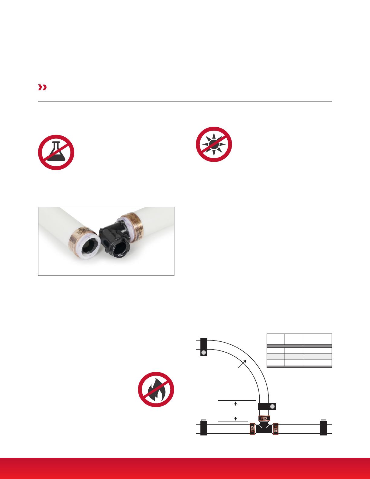
Mechanical Stress:
Fittings should be kept free of mechanical stress. Do
not subject polymer ttings to excessive impact. Do not
subject ttings to torque exceeding 100 lbs. of force.
Each joint should be properly supported. To avoid undue
stress on polymer ttings and connections, a minimum
distance of 2x the tubing O.D. should be allowed
before changing the direction of the tube. Sioux Chief
recommends always using a manufactured bend support.
Chemical Resistance:
Some chemicals can cause damage and should not come
in contact with polymer ttings. These chemicals include
(but are not limited to): Adhesives,
petroleum based substances, paints,
solvents, oxidizing agents, disinfectants,
PVC primers/solvents/cements, leak
detection liquids, oil/lubricants, pipe
dopes, ethylene glycol, or other volatile compounds. It
is the responsibility of the installing contractor to verify
compatibility of any chemicals that come into contact
with the PPSU ttings.
Special Considerations for Polymer Fittings 3.3
Polymer Fittings
Special Considerations for Use
Spray-Foam Compatibility
Some spray-foam insulation products are approved for
use with PEX tube and ttings. It is the responsibility of
the installing contractor to refer to information provided
by the insulation manufacturer and verify compatibility of
any foam or chemical foaming agents that will come into
contact with PowerPEX tube and ttings, including polymer
PowerPEX ttings. If insulation manufacturer recommends
wrapping PEX tube joints before application, see Section
5.5 for Requirements for Wrapping a PowerPEX joint.
Heat / Flame:
Do not subject polymer ttings to open
ame. Do not solder within 18" of
polymer ttings. Flame or heating
sources beyond material tolerances
must be avoided.
Polymer ttings that have been damaged by
chemicals MUST be removed from service.
TUBE
SIZE
2X
O.D.
MIN BEND
RADIUS*
1/2" 1.25" 3.75"
3/4" 1.75" 5.25"
1" 2.25" 6.75"
*Without bend support.
2x Tube OD
Min Bend
Radius
17 www.siouxchief.com
PEX Accessories
PEX Tube Cutter
USE: Hold cutter perpendicular to tubing. When cutter
is set at a right angle to tube length, squeeze handle
and cut tube ush. Slightly rotate tube cutter when blade
engages tubing OD to prevent "ovaling" the tube.
REPAIR: Remove screw and replace cutting blade with
replacement blade. Reassemble and replace the screw.
4
Tools & Accessories
Usage Guidelines
Go/No-Go Gauges
Gauges are available for both crimp
and compression sleeve systems.
All Sioux Chief PowerPEX tools
include Go/No-Go gauges
Coil Unwinder
USE: The unwinder remains in place on three stable legs
with adjustable feet while the coil swivels freely, making
it easy for users to pull tubing
as needed.
Crimp Ring Removal Tool
USE: Cut the tube close to the tting. Place ring removal
tool into the tting end and make two cuts approximately
3/8" apart. Remove ring sections with pliers. Twist
off tube. Inspect tting for reuse. Be sure barbs are
undamaged and tting has not been compromised.
NOTE: Not for use with PPSU or
other polymer ttings
Compression Insert (Tube Stiffener)
Stainless Steel or PPSU PEX inserts
must be used when a supply xture
valve will be pushed or compressed
onto PEX tube. ASSE 1061 push-t
ttings for use on plastic tubing must
use an insert sized appropriately to
the tube type ID.
Push Fit Disconnect Tools
USE: Load the properly-sized tool over the tube and
against the push tting. Squeeze/push the tool against
the tting socket to engage the release mechanism.
Pull tube/tting apart using a
twisting motion.
www.siouxchief.com 18
Crimp/Compression Tool Calibration
Check tool calibration regularly. It is recommended that at
least the rst and last crimp of the day/project is tested.
All tools include a Go/No-Go gauge - use the gauge to
determine if the tool needs calibration:
ITEM NO. DESCRIPTION
305-82TX Old style - 1/2" sleeve compression tool
305-84TX Old style - 1" sleeve compression tool
305-802 1/2" SS sleeve compression tool
305-803 3/4" SS sleeve compression tool
305-804 1" SS sleeve compression tool
Standard Sleeve Compression Tools
ITEM NO. DESCRIPTION
305-7023 1/2" & 3/4" Crimp tool with straight handle
305-7040 1" Crimp tool with straight handle
305-7050 1-1/4" Crimp tool with straight handle
305-7095 Crimp tool kit for 3/8", 1/2", 5/8", 3/4", 1"
Standard Crimp Tools
ITEM NO. DESCRIPTION
305-7110 3/8" Compact crimp tool with case
305-7120 1/2" Compact crimp tool with case
305-7123 1/2" & 3/4" Compact crimp tool with case
305-7130 3/4" Compact crimp tool with case
Compact Crimp Tools
ITEM NO. DESCRIPTION
305-92TX 1/2"
Compact Sleeve Compression Tools
Tool Repair & Calibration 4.2
ASTM F1807/F2159 Crimp & Compression Tools
All tools include an instruction sheet.
READ THE INSTRUCTION SHEET CAREFULLY AND UNDERSTAND IT.
1. If the crimped ring slides into the slot and stops in
the 'GO' area of the gauge, the crimp is GOOD
No calibration is needed.
2. If the crimped ring is too large to pass into the slot of
the gauge, the crimp is NO GOOD
Adjust tool by increasing number on calibration dial.
3. If the crimped ring slides into the 'NO GO' area of the
gauge, the crimp is NO GOOD
Adjust tool by decreasing number on calibration dial.
To Calibrate Standard Tools
- Open jaws and loosen LH or RH nuts on back of tool.
- Turn LH or RH calibration dial one increment at a time.
- Retighten nuts on back of tool.
- Perform a crimp and check with gauge.
To Calibrate Compact Tools
- Remove C-clip on back of tool with screwdriver.
- Push/rotate calibration dial one increment at a time.
- Replace C-clip with pliers.
- Perform a crimp and check with gauge.
Note:
- If you are not able to obtain good crimps after
calibration, the tool is likely worn and should be
replaced.
- Lubricate linkages regularly to maximize tool life.
- Do not remove Date Code sticker. Removal voids tool
warranty.
- Always place tools in a durable case or secure box
to protect the tool head from damage.
Note: Do Not gauge where jaw marks show on ring
19 www.siouxchief.com
Expansion Tool Verication and Use
1. Attach appropriately sized expansion head to an
ASTM F1960 expansion tool.
2. Ensure assembly is wholly intact and the male
threads of the tool or female threads of the jaw set are
not compromised.
3. Ensure the retention spring on the OD of the tool
jaw is in place and not compromised. If a jaw section is
missing or damaged, replace the expansion jaw.
4. Keep the expansion jaw and the tool driver
properly lubricated.
5. Place tool jaw into tube end/ring assembly and
compress handles to expand for tting install.
Note: For any battery issues with F1960 power tools
under warranty, call Sioux Chief customer service.
NEVER Use a damaged or misaligned expansion head.
NEVER Use mismatched tools and expansion heads or
tools and heads from different manufacturers.
4.3 ASTM F1960 Expansion Tools
Using PEX-B with ASTM F1960 Systems
PowerPEX Type-B tubing is approved for use with ASTM
F1960 ttings and expansion joints. If using a manual
tool, expand slowly and repeat expansions, rotating
expander 1/8-turn between expansions.
SIOUX CHIEF STRONGLY RECOMMENDS ALL ASTM F1960
EXPANSION JOINTS WITH POWERPEX® TYPE-B TUBING BE
MADE WITH A SELF-ROTATING, POWER EXPANSION TOOL.
Self-rotating, power expansion tools are designed to
automatically expand the tubing at the proper rate, while
rotating a set distance per activation. These features
assure the connection achieves the necessary tube ID
and overall connection geometry which
allow the tube and ttings to be used
together. When making ASTM
F1960 connections, proper tool
installation protocols must be maintained
per the manufacturer’s installation and
operating instructions.
Damaged Head
Worn springs can lead to
misaligned jaws and improper
expansion of tube.
ASTM F1960 Expansion Tools
All tools include an instruction sheet.
READ THE INSTRUCTION SHEET CAREFULLY.
Fitting Spacing
When installing F1960 ttings, it is important to keep
the minimum distance between expansions shown in the
table below:
PIPE SIZE MINIMUM DISTANCE
BETWEEN EXPANSIONS
3/8" 2.00"
1/2" 2.50"
3/4" 3.50"
1" 4.50"
1-1/4" 5.50"
1-1/2" 6.50"
2" 7.50"
ITEM NO. DESCRIPTION
305-W23KIT Expansion tool kit for 1/2" & 3/4" F1960
305-WT Expansion tool for F1960
305-W2H 1/2" F1960 expansion head
305-W3H 3/4" F1960 expansion head
305-W4H 1" F1960 expansion head
F1960 Expansion Tools
Expand Evenly
When expanding PEX tubing, especially large diameter
tubing or in low temperatures (below 55ºF), Do Not force
the tubing onto the expansion head in an attempt to
reduce the number of expansions.
Take care to expand slowly and evenly at the prescribed
rate of expansion. When using a manual tool,
expand slowly and rotate the tool.
  • Page 1 1
  • Page 2 2
  • Page 3 3
  • Page 4 4
  • Page 5 5
  • Page 6 6
  • Page 7 7
  • Page 8 8
  • Page 9 9
  • Page 10 10
  • Page 11 11
  • Page 12 12
  • Page 13 13
  • Page 14 14
  • Page 15 15
  • Page 16 16
  • Page 17 17
  • Page 18 18
  • Page 19 19
  • Page 20 20
  • Page 21 21
  • Page 22 22
  • Page 23 23
  • Page 24 24
  • Page 25 25
  • Page 26 26
  • Page 27 27
  • Page 28 28
  • Page 29 29
  • Page 30 30
  • Page 31 31
  • Page 32 32
  • Page 33 33
  • Page 34 34
  • Page 35 35
  • Page 36 36
  • Page 37 37
  • Page 38 38

Sioux Chief Elbow Installation guide

Type
Installation guide

Ask a question and I''ll find the answer in the document

Finding information in a document is now easier with AI