Page is loading ...

Motherboard
P4GPL-X

iiii
iiii
ii
Copyright © 2005 ASUSTeK COMPUTER INC. All Rights Reserved.Copyright © 2005 ASUSTeK COMPUTER INC. All Rights Reserved.
Copyright © 2005 ASUSTeK COMPUTER INC. All Rights Reserved.Copyright © 2005 ASUSTeK COMPUTER INC. All Rights Reserved.
Copyright © 2005 ASUSTeK COMPUTER INC. All Rights Reserved.
No part of this manual, including the products and software described in it, may be reproduced,
transmitted, transcribed, stored in a retrieval system, or translated into any language in any form
or by any means, except documentation kept by the purchaser for backup purposes, without the
express written permission of ASUSTeK COMPUTER INC. (“ASUS”).
Product warranty or service will not be extended if: (1) the product is repaired, modified or
altered, unless such repair, modification of alteration is authorized in writing by ASUS; or (2) the
serial number of the product is defaced or missing.
ASUS PROVIDES THIS MANUAL “AS IS” WITHOUT WARRANTY OF ANY KIND, EITHER EXPRESS OR
IMPLIED, INCLUDING BUT NOT LIMITED TO THE IMPLIED WARRANTIES OR CONDITIONS OF
MERCHANTABILITY OR FITNESS FOR A PARTICULAR PURPOSE. IN NO EVENT SHALL ASUS, ITS
DIRECTORS, OFFICERS, EMPLOYEES OR AGENTS BE LIABLE FOR ANY INDIRECT, SPECIAL,
INCIDENTAL, OR CONSEQUENTIAL DAMAGES (INCLUDING DAMAGES FOR LOSS OF PROFITS, LOSS
OF BUSINESS, LOSS OF USE OR DATA, INTERRUPTION OF BUSINESS AND THE LIKE), EVEN IF ASUS
HAS BEEN ADVISED OF THE POSSIBILITY OF SUCH DAMAGES ARISING FROM ANY DEFECT OR
ERROR IN THIS MANUAL OR PRODUCT.
SPECIFICATIONS AND INFORMATION CONTAINED IN THIS MANUAL ARE FURNISHED FOR
INFORMATIONAL USE ONLY, AND ARE SUBJECT TO CHANGE AT ANY TIME WITHOUT NOTICE, AND
SHOULD NOT BE CONSTRUED AS A COMMITMENT BY ASUS. ASUS ASSUMES NO RESPONSIBILITY
OR LIABILITY FOR ANY ERRORS OR INACCURACIES THAT MAY APPEAR IN THIS MANUAL,
INCLUDING THE PRODUCTS AND SOFTWARE DESCRIBED IN IT.
Products and corporate names appearing in this manual may or may not be registered
trademarks or copyrights of their respective companies, and are used only for identification or
explanation and to the owners’ benefit, without intent to infringe.
E1969E1969
E1969E1969
E1969
First Edition V1First Edition V1
First Edition V1First Edition V1
First Edition V1
February 2005February 2005
February 2005February 2005
February 2005

iiiiii
iiiiii
iii
Contents
Notices ................................................................................................ vi
Safety information ............................................................................. vii
P4GPL-X specifications summary ...................................................... viii
Chapter 1: Product introductionChapter 1: Product introduction
Chapter 1: Product introductionChapter 1: Product introduction
Chapter 1: Product introduction
1.1 Welcome! .............................................................................. 1-2
1.2 Package contents ................................................................. 1-2
1.3 Special features .................................................................... 1-2
1.3.1 Product highlights................................................... 1-2
1.3.2 ASUS AI Proactive features .................................... 1-4
1.3.3 Innovative ASUS features ....................................... 1-5
1.4 Before you proceed .............................................................. 1-6
1.5 Motherboard overview .......................................................... 1-7
1.5.1 Motherboard layout ................................................ 1-7
1.5.2 Placement direction ................................................ 1-8
1.5.3 Screw holes ............................................................ 1-8
1.6 Central Processing Unit (CPU) .............................................. 1-9
1.6.1 Overview ................................................................. 1-9
1.6.2 Installing the CPU.................................................... 1-9
1.6.3 Installing the heatsink and fan .............................. 1-12
1.7 System memory ................................................................. 1-15
1.7.1 Overview ............................................................... 1-15
1.7.2 Memory configurations ......................................... 1-15
1.7.3 Installing a DIMM ................................................... 1-17
1.7.4 Removing a DIMM ................................................. 1-17
1.8 Expansion slots ................................................................... 1-18
1.8.1 Installing an expansion card .................................. 1-18
1.8.2 Configuring an expansion card.............................. 1-18
1.8.3 PCI slots ................................................................ 1-20
1.8.4 PCI Express x16 slot ............................................. 1-20
1.8.5 PCI Express x1 slot ............................................... 1-20
1.9 Jumpers .............................................................................. 1-21
1.10 Connectors ......................................................................... 1-24
1.10.1 Rear panel connectors .......................................... 1-24
1.10.2 Internal connectors............................................... 1-26

iviv
iviv
iv
Contents
Chapter 2: BIOS setupChapter 2: BIOS setup
Chapter 2: BIOS setupChapter 2: BIOS setup
Chapter 2: BIOS setup
2.1 Managing and updating your BIOS ........................................ 2-2
2.1.1 Creating a bootable floppy disk .............................. 2-2
2.1.2 ASUS EZ Flash utility .............................................. 2-3
2.1.3 AFUDOS utility ........................................................ 2-4
2.1.4 ASUS CrashFree BIOS 2 utility ................................ 2-6
2.1.5 ASUS Update utility ................................................ 2-8
2.2 BIOS setup program ........................................................... 2-11
2.2.1 BIOS menu screen ................................................. 2-12
2.2.2 Menu bar ............................................................... 2-12
2.2.3 Navigation keys .................................................... 2-12
2.2.4 Menu items ........................................................... 2-13
2.2.5 Sub-menu items ................................................... 2-13
2.2.6 Configuration fields .............................................. 2-13
2.2.7 Pop-up window ..................................................... 2-13
2.2.8 Scroll bar .............................................................. 2-13
2.2.9 General help .......................................................... 2-13
2.3 Main menu .......................................................................... 2-14
2.3.1 System Time ......................................................... 2-14
2.3.2 System Date ......................................................... 2-14
2.3.3 Legacy Diskette A ................................................ 2-14
2.3.4 Primary, Third, and Fourth IDE Master/Slave ........ 2-15
2.3.5 IDE Configuration .................................................. 2-16
2.3.6 System Information .............................................. 2-17
2.4 Advanced menu .................................................................. 2-18
2.4.1 JumperFree Configuration .................................... 2-18
2.4.2 LAN Cable Status ................................................. 2-21
2.4.3 USB Configuration................................................. 2-22
2.4.4 CPU Configuration ................................................. 2-23
2.4.5 Chipset ................................................................. 2-24
2.4.6 Onboard Devices Configuration ............................ 2-26
2.4.7 PCI PnP ................................................................. 2-28

vv
vv
v
Contents
2.5 Power menu ........................................................................ 2-29
2.5.1 Suspend Mode ...................................................... 2-29
2.5.2 Repost Video on S3 Resume ................................ 2-29
2.5.3 ACPI 2.0 Support .................................................. 2-29
2.5.4 ACPI APIC Support ................................................ 2-29
2.5.5 APM Configuration ................................................ 2-30
2.5.6 Hardware Monitor ................................................. 2-32
2.6 Boot menu .......................................................................... 2-33
2.6.1 Boot Device Priority .............................................. 2-33
2.6.2 Boot Settings Configuration ................................. 2-34
2.6.3 Security ................................................................ 2-35
2.7 Exit menu ........................................................................... 2-37
Chapter 3: Software supportChapter 3: Software support
Chapter 3: Software supportChapter 3: Software support
Chapter 3: Software support
3.1 Installing an operating system ............................................. 3-2
3.2 Support CD information ........................................................ 3-2
3.2.1 Running the support CD ......................................... 3-2
3.2.2 Drivers menu .......................................................... 3-3
3.2.3 Utilities menu .......................................................... 3-4
3.2.4 ASUS Contact information ...................................... 3-6
3.2.5 Other information ................................................... 3-6

vivi
vivi
vi
Notices
Federal Communications Commission StatementFederal Communications Commission Statement
Federal Communications Commission StatementFederal Communications Commission Statement
Federal Communications Commission Statement
This device complies with Part 15 of the FCC Rules. Operation is subject to
the following two conditions:
•
This device may not cause harmful interference, and
•
This device must accept any interference received including interference
that may cause undesired operation.
This equipment has been tested and found to comply with the limits for a
Class B digital device, pursuant to Part 15 of the FCC Rules. These limits are
designed to provide reasonable protection against harmful interference in a
residential installation. This equipment generates, uses and can radiate radio
frequency energy and, if not installed and used in accordance with
manufacturer’s instructions, may cause harmful interference to radio
communications. However, there is no guarantee that interference will not
occur in a particular installation. If this equipment does cause harmful
interference to radio or television reception, which can be determined by
turning the equipment off and on, the user is encouraged to try to correct
the interference by one or more of the following measures:
•
Reorient or relocate the receiving antenna.
•
Increase the separation between the equipment and receiver.
•
Connect the equipment to an outlet on a circuit different from that to
which the receiver is connected.
•
Consult the dealer or an experienced radio/TV technician for help.
Canadian Department of Communications StatementCanadian Department of Communications Statement
Canadian Department of Communications StatementCanadian Department of Communications Statement
Canadian Department of Communications Statement
This digital apparatus does not exceed the Class B limits for radio noise
emissions from digital apparatus set out in the Radio Interference
Regulations of the Canadian Department of Communications.
This class B digital apparatus complies with CanadianThis class B digital apparatus complies with Canadian
This class B digital apparatus complies with CanadianThis class B digital apparatus complies with Canadian
This class B digital apparatus complies with Canadian
ICES-003.ICES-003.
ICES-003.ICES-003.
ICES-003.
The use of shielded cables for connection of the monitor to the graphics
card is required to assure compliance with FCC regulations. Changes or
modifications to this unit not expressly approved by the party
responsible for compliance could void the user’s authority to operate
this equipment.

viivii
viivii
vii
Safety information
Electrical safetyElectrical safety
Electrical safetyElectrical safety
Electrical safety
•
To prevent electrical shock hazard, disconnect the power cable from the
electrical outlet before relocating the system.
•
When adding or removing devices to or from the system, ensure that the
power cables for the devices are unplugged before the signal cables are
connected. If possible, disconnect all power cables from the existing
system before you add a device.
•
Before connecting or removing signal cables from the motherboard,
ensure that all power cables are unplugged.
•
Seek professional assistance before using an adapter or extension cord.
These devices could interrupt the grounding circuit.
•
Make sure that your power supply is set to the correct voltage in your
area. If you are not sure about the voltage of the electrical outlet you are
using, contact your local power company.
•
If the power supply is broken, do not try to fix it by yourself. Contact a
qualified service technician or your retailer.
Operation safetyOperation safety
Operation safetyOperation safety
Operation safety
•
Before installing the motherboard and adding devices on it, carefully read
all the manuals that came with the package.
•
Before using the product, make sure all cables are correctly connected
and the power cables are not damaged. If you detect any damage,
contact your dealer immediately.
•
To avoid short circuits, keep paper clips, screws, and staples away from
connectors, slots, sockets and circuitry.
•
Avoid dust, humidity, and temperature extremes. Do not place the
product in any area where it may become wet.
•
Place the product on a stable surface.
•
If you encounter technical problems with the product, contact a qualified
service technician or your retailer.

viiiviii
viiiviii
viii
P4GPL-X specifications summary
(continued on the next page)
CPUCPU
CPUCPU
CPU
ChipsetChipset
ChipsetChipset
Chipset
Front Side BusFront Side Bus
Front Side BusFront Side Bus
Front Side Bus
MemoryMemory
MemoryMemory
Memory
Expansion slotsExpansion slots
Expansion slotsExpansion slots
Expansion slots
StorageStorage
StorageStorage
Storage
High DefinitionHigh Definition
High DefinitionHigh Definition
High Definition
AudioAudio
AudioAudio
Audio
LANLAN
LANLAN
LAN
OverclockingOverclocking
OverclockingOverclocking
Overclocking
USBUSB
USBUSB
USB
Special featuresSpecial features
Special featuresSpecial features
Special features
Socket 478 for Intel
®
Pentium
®
4 / Celeron processors
Supports Intel
®
Hyper-Threading Technology
Northbridge: Intel
®
915PL Memory Controller Hub (MCH)
Southbridge: Intel
®
ICH6
800/533/400 MHz
Dual-channel memory architecture
2 x 184-pin DIMM sockets support up to 2 GB of
unbufferred non-ECC 400/333 MHz DDR memory
modules
1 x PCI Express™ x16 slot for discrete graphics card
3 x PCI Express™ x1 slots
3 x PCI slots
Intel
®
ICH6 Southbridge supports:
- 2 x Ultra DMA 100/66/33 hard disk drives
- 4 x Serial ATA drives
Intel
®
High Definition Audio
Realtek
®
ALC880 8-channel CODEC
Coaxial S/PDIF out port
Marvell
®
88E8053 PCI Express™ Gigabit LAN controller
Supports Marvell
®
Virtual Cable Tester Technology
ASUS AI Overclocking (Intelligent CPU frequency tuner)
ASUS C.P.R. (CPU Parameter Recall)
Adjustable CPU, Memory, and Chipset core voltages
Stepless Frequency Selection(SFS) from 100 MHz up
to 400 MHz at 1 MHz increment
Adjustable FSB/DDR ratio with fixed PCI/PCI-Express
frequencies
Supports up to 8 USB 2.0 ports
AI NET 2
ASUS CrashFree BIOS 2
ASUS EZ Flash
ASUS MyLogo2™
ASUS Hyperpath 2 Technology
ASUS C.P.R. (CPU Parameter Recall)

ixix
ixix
ix
*Specifications are subject to change without notice.
P4GPL-X specifications summary
BIOS featuresBIOS features
BIOS featuresBIOS features
BIOS features
Rear panelRear panel
Rear panelRear panel
Rear panel
InternalInternal
InternalInternal
Internal
connectorsconnectors
connectorsconnectors
connectors
PowerPower
PowerPower
Power
RequirementRequirement
RequirementRequirement
Requirement
Form FactorForm Factor
Form FactorForm Factor
Form Factor
Support CDSupport CD
Support CDSupport CD
Support CD
contentscontents
contentscontents
contents
4 MB Flash ROM, AMI BIOS, Green, PnP, DMI2.0,
SM BIOS 2.3, WfM2.0, ACPI 2.0
1 x Parallel port
1 x LAN (RJ-45) port
4 x USB 2.0 ports
1 x Serial port (COM)
1 x Coaxial S/PDIF out port
1 x PS/2 keyboard port
1 x PS/2 mouse port
8-channel audio ports
1 x Floppy disk drive connector
1 x Primary IDE connector
4 x Serial ATA connectors
1 x CPU fan connector
1 x Chassis fan connector
2 x USB 2.0 connectors for four additional USB 2.0 ports
1 x Optical drive audio connector
24-pin ATX power connector
4-pin x ATX 12V power connector
1 x Front panel High Definition Audio connector
System panel connector
ATX power supply (with 24-pin and 4-pin 12 V plugs)
ATX 12 V 2.0 compliant
ATX form factor: 12 in x 9.6 in (30.5 cm x 24.4 cm)
Device drivers
ASUS PC Probe
ASUS Live Update utility
Anti-virus software (OEM version)

xx
xx
x

1
Product
introduction
This chapter describes the motherboard
features and the new technologies
it supports.

1-21-2
1-21-2
1-2
Chapter 1: Product introductionChapter 1: Product introduction
Chapter 1: Product introductionChapter 1: Product introduction
Chapter 1: Product introduction
1.3 Special features
1.3.11.3.1
1.3.11.3.1
1.3.1
Product highlightsProduct highlights
Product highlightsProduct highlights
Product highlights
Latest processor technology Latest processor technology
Latest processor technology Latest processor technology
Latest processor technology
The motherboard comes with a 478-pin surface mount, Zero Insertion
Force (ZIF) socket for the Intel
®
Pentium
®
4 processor in the 478-pin
package with 1 MB/512 KB/256 KB L2 cache. This motherboard supports
800/533/400 MHz system front side bus that allows 6.4 GB/s and
4.3 GB/s data transfer rates, respectively. The motherboard also supports
Intel
®
Pentium
®
4 processors with Hyper-Threading Technology.
1.1 Welcome!
Thank you for buying an ASUSThank you for buying an ASUS
Thank you for buying an ASUSThank you for buying an ASUS
Thank you for buying an ASUS
®®
®®
®
P4GPL-X motherboard! P4GPL-X motherboard!
P4GPL-X motherboard! P4GPL-X motherboard!
P4GPL-X motherboard!
The motherboard delivers a host of new features and latest technologies,
making it another standout in the long line of ASUS quality motherboards!
Before you start installing the motherboard, and hardware devices on it,
check the items in your package with the list below.
If any of the above items is damaged or missing, contact your retailer.
1.2 Package contents
Check your motherboard package for the following items.
MotherboardMotherboard
MotherboardMotherboard
Motherboard ASUS P4GPL-X motherboard
CablesCables
CablesCables
Cables 1 x Serial ATA signal cable
1 x Serial ATA power cable
1 x Ultra DMA 133/100/66 cable
Floppy disk drive cable
AccessoriesAccessories
AccessoriesAccessories
Accessories I/O shield
Application CDsApplication CDs
Application CDsApplication CDs
Application CDs ASUS motherboard support CD
DocumentationDocumentation
DocumentationDocumentation
Documentation User guide

ASUS P4GPL-XASUS P4GPL-X
ASUS P4GPL-XASUS P4GPL-X
ASUS P4GPL-X
1-31-3
1-31-3
1-3
IntelIntel
IntelIntel
Intel
®®
®®
®
915PL and Intel 915PL and Intel
915PL and Intel 915PL and Intel
915PL and Intel
®®
®®
®
ICH6 chipset ICH6 chipset
ICH6 chipset ICH6 chipset
ICH6 chipset
The Intel
®
915PL chipset provides the interface for a processor in the
478-pin package with 800/533/400MHz front side bus (FSB), dual channel
DDR at speeds of up to 400 MHz, and PCI Express x16 graphics card
interface. The ICH6 Southbridge provides integrated support for four Serial
ATA ports, PCI Express slots, and eight high-speed USB 2.0 ports.
Dual-channel DDR memory support Dual-channel DDR memory support
Dual-channel DDR memory support Dual-channel DDR memory support
Dual-channel DDR memory support
Employing the Double Data Rate (DDR) memory technology, the
motherboard supports up to 2 GB of system memory using DDR400/333
DIMMs. The ultra-fast 400MHz memory bus delivers the required bandwidth
for the latest 3D graphics, multimedia, and Internet applications. See page
1-15 for details.
PCI Express™ interface PCI Express™ interface
PCI Express™ interface PCI Express™ interface
PCI Express™ interface
The motherboard fully supports PCI Express, the latest I/O interconnect
technology that speeds up the PCI bus. PCI Express features point-to-point
serial interconnections between devices and allows higher clockspeeds by
carrying data in packets. This high speed interface is software compatible with
existing PCI specifications. See page 1-20 for details.
Serial ATA technology Serial ATA technology
Serial ATA technology Serial ATA technology
Serial ATA technology
The motherboard supports the Serial ATA technology through the Serial ATA
interfaces and the Intel
®
ICH6. The SATA specification allows for thinner,
more flexible cables with lower pin count, reduced voltage requirement, and
up to 150 MB/s data transfer rate. See page 1-28 for details.
8-channel high definition audio 8-channel high definition audio
8-channel high definition audio 8-channel high definition audio
8-channel high definition audio
The motherboard supports 8-channel High Definition Audio through the
onboard ALC880 CODEC with 24-bit DAC, a stereo 16-bit ADC, and an
AC97 2.3 compatible multi-channel audio designed for PC multimedia
systems. It also provides a Jack-Sensing function, S/PDIF out support,
interrupt capability and includes the Realtek
®
proprietary UAJ
®
(Universal
Audio Jack) technology. See pages 1-24 and 1-25 for details.
S/PDIF digital sound ready S/PDIF digital sound ready
S/PDIF digital sound ready S/PDIF digital sound ready
S/PDIF digital sound ready
The motherboard supports the S/PDIF Out function through the S/PDIF
interfaces on the rear panel and at midboard. The S/PDIF technology turns
your computer into a high-end entertainment system with digital connectivity
to powerful audio and speaker systems. See page 1-25 for details.

1-41-4
1-41-4
1-4
Chapter 1: Product introductionChapter 1: Product introduction
Chapter 1: Product introductionChapter 1: Product introduction
Chapter 1: Product introduction
1.3.21.3.2
1.3.21.3.2
1.3.2
ASUS AI Proactive featuresASUS AI Proactive features
ASUS AI Proactive featuresASUS AI Proactive features
ASUS AI Proactive features
AI NET2 AI NET2
AI NET2 AI NET2
AI NET2
The AI NET2 is a BIOS-based diagnostic tool that detects and reports
Ethernet cable faults and shorts. With this utility, you can easily monitor
the condition of the Ethernet cable(s) connected to the LAN (RJ-45)
port(s). During the bootup process, AI NET2 immediately diagnoses the
LAN cable(s) and reports shorts and faults up to 100 meters at 1 meter
accuracy.
ASUS Hyper Path 2 technology ASUS Hyper Path 2 technology
ASUS Hyper Path 2 technology ASUS Hyper Path 2 technology
ASUS Hyper Path 2 technology
The ASUS Hyper Path 2 technology optimizes the full potential of the Intel
®
chipset by shortening the latency time between the CPU and the system
memory. Enabling Hyper Path 2 on systems with the Intel
®
PAT improves
memory performance without affecting system stability. See page 2-25 for
details.
USB 2.0 technology USB 2.0 technology
USB 2.0 technology USB 2.0 technology
USB 2.0 technology
The motherboard implements the Universal Serial Bus (USB) 2.0
specification, dramatically increasing the connection speed from the
12 Mbps bandwidth on USB 1.1 to a fast 480 Mbps on USB 2.0. USB 2.0 is
backward compatible with USB 1.1. See pages 1-25 and 1-30 for details.
Temperature, fan, and voltage monitoringTemperature, fan, and voltage monitoring
Temperature, fan, and voltage monitoringTemperature, fan, and voltage monitoring
Temperature, fan, and voltage monitoring
The CPU temperature is monitored by the ASIC (integrated in the Winbond
Super I/O) to prevent overheating and damage. The system fan rotations
per minute (RPM) is monitored for timely failure detection. The ASIC
monitors the voltage levels to ensure stable supply of current for critical
components. See page 2-32 for details.

ASUS P4GPL-XASUS P4GPL-X
ASUS P4GPL-XASUS P4GPL-X
ASUS P4GPL-X
1-51-5
1-51-5
1-5
1.3.31.3.3
1.3.31.3.3
1.3.3
Innovative ASUS featuresInnovative ASUS features
Innovative ASUS featuresInnovative ASUS features
Innovative ASUS features
CrashFree BIOS 2 CrashFree BIOS 2
CrashFree BIOS 2 CrashFree BIOS 2
CrashFree BIOS 2
This feature allows you to restore the original BIOS data from the support CD
in case when the BIOS codes and data are corrupted. This protection
eliminates the need to buy a replacement ROM chip. See details on page 2-6.
ASUS EZ Flash BIOS ASUS EZ Flash BIOS
ASUS EZ Flash BIOS ASUS EZ Flash BIOS
ASUS EZ Flash BIOS
With the ASUS EZ Flash, you can easily update the system BIOS even
before loading the operating system. No need to use a DOS-based utility or
boot from a floppy disk. See page 2-3 for details.
ASUS MyLogo2™ ASUS MyLogo2™
ASUS MyLogo2™ ASUS MyLogo2™
ASUS MyLogo2™
This feature allows you to personalize and add style to your system with
customizable boot logos. See page 2-34 for details.
C.P.R. (CPU Parameter Recall) C.P.R. (CPU Parameter Recall)
C.P.R. (CPU Parameter Recall) C.P.R. (CPU Parameter Recall)
C.P.R. (CPU Parameter Recall)
The C.P.R. feature of the motherboard BIOS allows automatic re-setting to
the BIOS default settings in case the system hangs due to overclocking.
When the system hangs due to overclocking, C.P.R. eliminates the need to
open the system chassis and clear the RTC data. Simply shut down and
reboot the system, and the BIOS automatically restores the CPU default
setting for each parameter.

1-61-6
1-61-6
1-6
Chapter 1: Product introductionChapter 1: Product introduction
Chapter 1: Product introductionChapter 1: Product introduction
Chapter 1: Product introduction
Onboard LEDOnboard LED
Onboard LEDOnboard LED
Onboard LED
The motherboard comes with a standby power LED that lights up to
indicate that the system is ON, in sleep mode, or in soft-off mode.
This is a reminder that you should shut down the system and unplug
the power cable before removing or plugging in any motherboard
component. The illustration below shows the location of the onboard
LED.
1.4 Before you proceed
Take note of the following precautions before you install motherboard
components or change any motherboard settings.
• Unplug the power cord from the wall socket before touching any
component.
• Use a grounded wrist strap or touch a safely grounded object or a
metal object, such as the power supply case, before handling
components to avoid damaging them due to static electricity
• Hold components by the edges to avoid touching the ICs on them.
• Whenever you uninstall any component, place it on a grounded
antistatic pad or in the bag that came with the component.
•
Before you install or remove any component, ensureBefore you install or remove any component, ensure
Before you install or remove any component, ensureBefore you install or remove any component, ensure
Before you install or remove any component, ensure
that the ATX power supply is switched off or thethat the ATX power supply is switched off or the
that the ATX power supply is switched off or thethat the ATX power supply is switched off or the
that the ATX power supply is switched off or the
power cord is detached from the power supply. power cord is detached from the power supply.
power cord is detached from the power supply. power cord is detached from the power supply.
power cord is detached from the power supply. Failure
to do so may cause severe damage to the motherboard, peripherals,
and/or components.
P4GPL-X
P4GPL-X Onboard LED
SB_PWR
ON
Standby
Power
OFF
Powere
d
Off

ASUS P4GPL-XASUS P4GPL-X
ASUS P4GPL-XASUS P4GPL-X
ASUS P4GPL-X
1-71-7
1-71-7
1-7
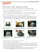
1.5.11.5.1
1.5.11.5.1
1.5.1
Motherboard layoutMotherboard layout
Motherboard layoutMotherboard layout
Motherboard layout
1.5 Motherboard overview
P4GPL-X
CR2032 3V
Lithium Cell
CMOS Power
CD
Super
I/O
Intel FWH
4Mb
ATX12V
FLOPPY
AAFP
DDR DIMM_A1 (64 bit,184-pin module)
KBPWR
SB_PWR
USBPW34
USBPW12
24.4cm (9.6in)
30.5cm (12.0in)
PANEL
USB78
USB56
USBPW78
USBPW56
CLRTC
SATA1
CHA_FAN
PCI1
Intel
®
915PL
Intel
ICH6
DDR DIMM_B1 (64 bit,184-pin module)
CPU_FAN
PRI_IDE
ALC880
EATXPWR
SATA3
SATA2
SATA4
PCI2
PCI3
Marvell
88E8053
R
PS/2KBMS
T: Mouse
B: Keyboard
Below:Mic In
Center:Line Out
Top:Line In
PARALLEL PORT
COM1
SPDIF_O
F_USB12
LAN_USB34
PCIEX1_1
PCIEX1_2
PCIEX1_3
PCIEX16
Socket 478
Below:Bass
Center:
Side surround L/R
Top:
Back surround L/R

1-81-8
1-81-8
1-8
Chapter 1: Product introductionChapter 1: Product introduction
Chapter 1: Product introductionChapter 1: Product introduction
Chapter 1: Product introduction
P4GPL-X
Do not overtighten the screws! Doing so can damage the motherboard.
1.5.21.5.2
1.5.21.5.2
1.5.2
Placement directionPlacement direction
Placement directionPlacement direction
Placement direction
When installing the motherboard, make sure that you place it into the
chassis in the correct orientation. The edge with external ports goes to the
rear part of the chassis as indicated in the image below.
Place this side towardsPlace this side towards
Place this side towardsPlace this side towards
Place this side towards
the rear of the chassisthe rear of the chassis
the rear of the chassisthe rear of the chassis
the rear of the chassis
1.5.31.5.3
1.5.31.5.3
1.5.3
Screw holesScrew holes
Screw holesScrew holes
Screw holes
Place nine (9) screws into the holes indicated by circles to secure the
motherboard to the chassis.

ASUS P4GPL-XASUS P4GPL-X
ASUS P4GPL-XASUS P4GPL-X
ASUS P4GPL-X
1-91-9
1-91-9
1-9
Take note of the marked corner (with
gold triangle) on the CPU. This mark
should match a specific corner on the
socket to ensure correct installation.
Incorrect installation of the CPU into the socket can bend the pins and
severely damage the CPU!
Gold mark
1.6.11.6.1
1.6.11.6.1
1.6.1
OverviewOverview
OverviewOverview
Overview
The motherboard comes with a surface mount 478-pin Zero Insertion Force
(ZIF) socket designed for the Intel
®
Pentium
®
4 Processor.
1.6 Central Processing Unit (CPU)
1.6.21.6.2
1.6.21.6.2
1.6.2
Installing the CPUInstalling the CPU
Installing the CPUInstalling the CPU
Installing the CPU
Follow these steps to install a CPU.
1. Locate the 478-pin ZIF socket on the motherboard.
Your boxed Intel
®
Pentium
®
4 processor package should come with
installation instructions for the CPU, heatsink, and the retention
mechanism. If the instructions in this section do not match the CPU
documentation, follow the latter.
P4GPL-X
P4GPL-X Socket 478
Gold Arrow

1-101-10
1-101-10
1-10
Chapter 1: Product introductionChapter 1: Product introduction
Chapter 1: Product introductionChapter 1: Product introduction
Chapter 1: Product introduction
Socket leverSocket lever
Socket leverSocket lever
Socket lever
90°-100°90°-100°
90°-100°90°-100°
90°-100°
angleangle
angleangle
angle
Make sure that the socket lever is lifted up to 90°-100° angle;
otherwise, the CPU does not fit in completely.
3. Position the CPU above the
socket such that its marked
corner matches the base of the
socket lever.
4. Carefully insert the CPU into the
socket until it fits in place.
The CPU fits only in one correct orientation. DO NOT force the CPU into
the socket to prevent bending the pins and damaging the CPU!
Gold markGold mark
Gold markGold mark
Gold mark
2. Unlock the socket by pressing
the lever sideways, then lift it up
to a 90°-100° angle.
/