
i


Revision History
Changes to the original manual are listed below:
Version Date Description of Version
1.0 September 21, 2010 Initial release.
1.1 February 21, 2011 Added Power save mode and examples for
trigger command.
1.2 April 27, 2011 Corrected blurry barcode images in the Test
Mode Setting section.
1.3 May 11, 2011 Updated Trigger Command Format section.
1.4 June 23, 2011 Added description in Edge Trigger Command.
1.5 May 17, 2013 Corrected ASCII code in appendix
1.6 May 13, 2014 Added Multi-Barcode Editor
High-Speed Laser Scan Module Series
i

Important Notice
No warranty of any kind is made in regard to this material, including, but not limited to, implied
warranties of merchantability or fitness for a particular purpose. We are not liable for any errors
contained herein or incidental or consequential damages in connection with furnishing,
performance or use of this material.
No part of this document may be reproduced, transmitted, stored in a retrieval system, transcribed,
or translated into any language or computer language in any form or by any means electronic,
mechanical, magnetic, optical, chemical, manual or otherwise, without express written consent
and authorization.
We reserve the right to make changes in product design without reservation and without
notification. The material in this guide is for information only and is subject to change without
notice.
All trademarks mentioned herein, registered or otherwise, are the properties of their various
respective owners.
Copyright © 2014. All rights reserved.
Radio Notice
This equipment generates uses and can radiate radio frequency energy. If not installed and used
in accordance with the instructions in this manual, it may cause interference to radio
communications. The equipment has been tested and found to comply with the limits for a Class
A computing device pursuant to EN55022 and 47 CFR, Part 2 and Part 15 of the FCC rules. These
specifications are designed to provide reasonable protection against interference when operated in
a commercial environment.
Radio and Television Interference
Operation of this equipment in a residential area can cause interference to radio or television
reception. This can be determined by turning the equipment off and on. The user is encouraged
to try to correct the interference by one or more of the following measures:
Reorient the receiving antenna.
Relocate the device with respect to the receiver.
Move the device away from the receiver.
Plug the device into a different outlet so that the device and the receiver are on different
branch circuits.
If necessary the user may consult the manufacturer, and authorized dealer, or experienced
radio/television technician for additional suggestions. The user may find the following booklet
prepared by the Federal Communications Commission helpful: “How to Identify and Resolve Radio-
TV Interference Problems.” This booklet is available from the U.S. Government Printing Office,
Washington, DC 20402 U.S.A., Stock No. 004000003454.
Guidance for Printing
This manual is in A5 size. Please double check your printer setting before printing it out.
When the barcodes are to be printed for programming, the use of a high-resolution laser
printer is strongly suggested for the best scan result.
High-Speed Laser Scan Module Series
ii

Laser Safety
The laser scanner complies with safety standard IEC 60825 -1 for a Class I laser produce. It also
complies with CDRH as applicable to a Class IIa laser product. Avoid long term staring into direct
laser light.
Radiant Energy: The laser scanner uses one low-power visible laser diodes operating at 650nm in
an optical mechanical scanner resulting in less than 3.9μW radiated power as observed through a
7mm aperture and averaged over 10 seconds.
Do not attempt to remove the protective housing of the scanner, as unscanned laser light with a
peak output up to 0.8mW would be accessible inside.
Laser Light Viewing: The scan window is the only aperture through which laser light may be
observed from this product. A failure of the scanner motor, while the laser diode continues to
emit a laser beam, may cause emission levels to exceed those for safe operation. The scanner has
safeguards to prevent this occurrence. If, however, a stationary laser beam is emitted, the failing
scanner should be disconnected from its power source immediately.
Adjustments: Do not attempt any adjustments or alteration of this product. Do not remove the
protective housing of the scanner. There are no user-serviceable parts inside.
Caution: Use of controls or adjustments or performance of procedures other than those specified
herein may result in hazardous laser light exposure.
Optical: The use of optical instruments with this product will increase the eye hazard. Optical
instruments include binoculars, magnifying glasses, and microscopes but do not include normal eye
glasses worn by the user.
General Handling Precautions
• Do not dispose of the scanner in fire.
• Do not put the scanner directly in the sun or by any heat source.
• Do not use or store the scanner in a very humid place.
• Do not drop the scanner or allow it to collide violently with other objects.
• Do not take the scanner apart without authorization.
For CE-countries:
The Scanner is in conformity with the CE standards. Please note that an approved, CE-Marked
power supply unit should be used to conform to these standards.
High-Speed Laser Scan Module Series
iii

High-Speed Laser Scan Module Series
iv
Table of Contents
Introduction .........................................................................................................................1
Safety Label ................................................................................................................2
Scanner Components .................................................................................................2
Maintaining the Scanner ............................................................................................3
Connection...........................................................................................................................4
Power .........................................................................................................................4
Connecting to the Host...............................................................................................4
Interface Cable ..................................................................................................4
Installation ...........................................................................................................................5
Mounting....................................................................................................................5
Diagrams for Mounting ..............................................................................................5
Window Instructions ..................................................................................................6
Set Up...................................................................................................................................7
Configuring the Scanner .............................................................................................7
Power-Up Self Test .....................................................................................................7
Scan Test.....................................................................................................................7
Controlling the Scanner from the Host ......................................................................8
Operation ...........................................................................................................................10
Visible Indicators ......................................................................................................10
Sound Indicators.......................................................................................................10
Sleep Mode...............................................................................................................11
Position Object Detector ..........................................................................................11
Position Scanner and Barcode Label ........................................................................12
Read Rate Test (Standard and High Definition)........................................................14
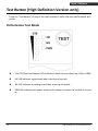
Test Button (High Definition Version only) ...............................................................15
Performance Test Mode..................................................................................15
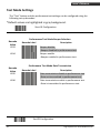
Test Mode Settings..........................................................................................17
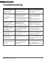
Troubleshooting .................................................................................................................18
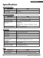
Specification.......................................................................................................................19
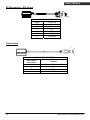
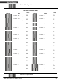
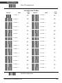
Pin Assignment...................................................................................................................20
Dimension ..........................................................................................................................22
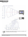
Scan Zone...........................................................................................................................23
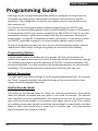
Programming Guide ...........................................................................................................25
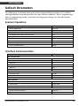
Default Parameters...................................................................................................26
Scanner Operation ..........................................................................................26
Interface Communication ...............................................................................26
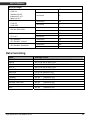
Symbologies....................................................................................................27
Data Formating ...............................................................................................28
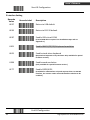
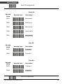
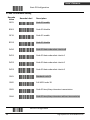
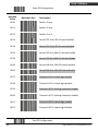
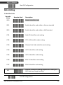
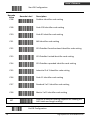
Program Procedure Using Barcode Manual.............................................................29
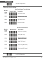
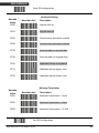
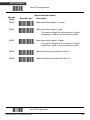
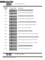
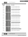
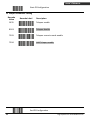
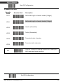
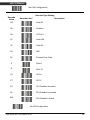
Parameter Setting ....................................................................................................30
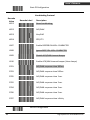
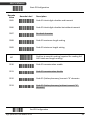
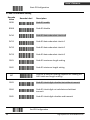
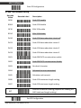
Scanner Operation ..........................................................................................30
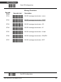
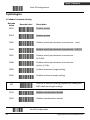
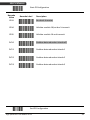
Interface Setting .............................................................................................43
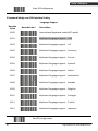
Symbologies....................................................................................................51
Data Editing.....................................................................................................74
Appendix 1: USB Virtual COM Driver Installation ...........................................79
Appendix 2: Barcode Length Setting...............................................................80
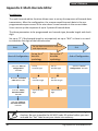
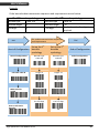
Appendix 3: Multi-Barcode Editor...................................................................81
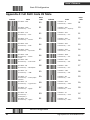
Appendix 4: Full ASCII Code 39 Table .............................................................83

High-Speed Laser Scan Module Series
1
USER’S MANUAL
Introduction
This manual applies to the high-speed laser scan module series, including single-line laser
scan module and high-density laser scan module. Different models share similar setting
while differ in hardware and operations.
This series is small-in-size, light-in-weight, durable-in-structure and fast-in-reading, an
overwhelming scan module in the industrial market.
With high-speed laser scan engine embedded, it offers a reading rate of 500 scans per
second. Its hardware decode technology provides real-time decoding that effectively
shortens customers’ transaction time, the optimized choice to meet fast-reading
requirement.
It is featured with “sleep mode” in which the laser and the motor would be switched off
sequentially in order to minimize electricity consumption and prolong product life.
Additionally, it automatically reads barcodes approaching the scan window, which means
it is not necessary to push any button to proceed scanning.
This fixed position scanner works perfectly inside retailing price-checking machines,
kiosks, medical devices and etc., aiming to provide easy-to-use and reliable user
experience.
Superior optical performance
Good read LED indicator and tone programmable beeper
Built-in decoder allowing automatic recognition of most barcode symbologies
Programmable operation settings to cater to user’s preference
Simplified command programmable via RS-232C interface
IR sensing for quick scanner wake up when scanner enters sleep mode
Unpacking the Scanner
The laser scan module package should contain:
1ea. Laser scan module with attached interface cable
1ea. 5V power adapter (model depending on electrical requirements)
1ea. User’s Manual (in hardcopy or CD)
Please contact your dealer if there is any damaged or missing item.

High-Speed Laser Scan Module Series
2
USER’S MANUAL
Safety Label
The Scanner complies with safety standard IEC60825-1 for a class I laser product.
It also complies with U.S21CFR1040 as applicable to a class IIa laser product.
Avoid direct long-term viewing at the laser light.
Caution label for standard version
Caution label for high density version
This equipment generates uses and can radiate radio frequency energy. If not installed
and used in accordance with the instructions in this manual, it may cause interference to
radio communications. The equipment has been tested and found to comply with the
limits for a Class A computing device pursuant to EN55022 and 47 CFR, part2 and Part 15
of FCC Rules. These specifications are designed to provide reasonable protection against
interference when operated in a commercial environment.
Scanner Components
Front view
Exit Window
Interface Cable
Indicator
Buzzer
Object Detector

High-Speed Laser Scan Module Series
3
USER’S MANUAL
Bottom view
Back Mount Holes
Product Serial La
bel
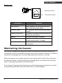
Description Function
Exit Window Reads barcodes
LED Indicator When power is on, LED turns Red; for a
good read, green light blinks.
Interface Cable For interface communication and power
supply.
Product Serial Label Contents the model name and serial NO.
Please do not remove.
Beeper A single tone beeps indication.
Object Detector Trigger and wake up scanner when
presenting barcode in its range
Back Mount Hole To fix the scanner to your host
instrument.
Maintaining the Scanner
The scanner is designed for long-term trouble-free operation and rarely requires any
maintenance. Only an occasional cleaning of the scanner window is necessary in order to
remove dirt and fingerprints. It can be cleaned while the scanner is running.
When cleaning the scan window, wipe the scan window with a soft lint-free cloth and a
non-abrasive cleaner to avoid scratching and damaging the scan window. Do not spray
water or cleaning liquid directly into the window.
If the scanner’s housing needs cleaning, use a mild cleaning agent that does not contain
strong oxidizing chemicals; otherwise the exterior may be damaged.

High-Speed Laser Scan Module Series
4
USER’S MANUAL
Connection
Power
The scanner requires a minimum of 210mA at 5 V DC power. The interface cable that
comes with the scanner supports both direct power (where the scanner takes power
from the host machine) and external power (that's what the supplied power adapter is
for). A sufficiently robust host system can support a scanner successfully without external
power; a host system with a barely adequate power supply may produce erratic
performance (either of the host system itself, or of the scanner, or both) when a scanner
is attached. Unless you are sure your host system can handle the load, it is recommended
that you use the supplied power adapter. In most cases, external power is not required
for keyboard and USB interface. When an external adapter is connected, the scanner
does not take power from the host.
The scanner turns on when power is supplied, and turns off when power is removed.
There is no on/off switch on the scanner itself.
Use only an AC/DC power adapter approved for the scanner. Use of other power supplies
may cause damage to the product, and void the factory warranty.
Connecting to the Host
The power link interface cable comes with different host-end connectors, depending on
the host. Follow the steps below to connect the interface cable to the host.
1. Make sure that the power of the host system is off.
2. Plug the host end of the interface cable to the appropriate connector on the host
system.
3. For those cases where external power is used, plug the external AC power adapter
into the jack on the interface cable.
4. Turn on the host system.
The scan
ner will light up for 3 seconds after turned on in case it is accidentally
set to be in the trigger mode and needs re-set.
Interface Cable
The interface cable comes with different host-end connectors, depending on the host.
There are 3 standard types of interface connection that this device supports:
(a) Keyboard wedge
(b) RS-232 interface
(c) USB interface (supporting HID USB and virtual COM USB)
The interface cable is not field-replaceable and unauthorized change to hardware may
void warranty. For cable replacements please contact your distributor.

High-Speed Laser Scan Module Series
5
USER’S MANUAL
Installation
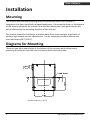
Mounting
The scanner has reserved mounting holes for permanent fixture to a surface or
integration into your specifically-designed equipment. Use mounting holes on the bottom
of the scanner to mount the scanner onto the desired position. Scan performance will
not be affected by the mounting direction of the scanner.
The scanner should be installed in a location away from direct sunlight; high levels of
ambient light reduce scanner effectiveness. The air temperature around the scanner
must not exceed 40°C (104°F).
Diagrams for Mounting
There are two back mount holes at the bottom of the scanner, which allows easily
mounting the scanner onto the host instrument with only two screws.
Screw Size:M2 x 0.4 x 6 mm

High-Speed Laser Scan Module Series
6
USER’S MANUAL
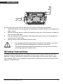
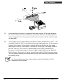
To correctly mount the scanner onto the host device, follow the steps below:
1. Locate the device in a dry position to avoid direct sunlight, bright or laser light from
other source.
2. Before mounting, ensure sufficient clearance at the rear of the scanner to allow for
the connector and cable
3. Use the measurements provided in the figure to locate centers of mounting holes
and drill two 2.2mm holes.
4. Secure scanner with two M2x0.4-6mm screws.
Do not allow the mounting screws to penetrate the scanner case more
than 0.235in (6mm) or damage to the scanner may result.
To preve
nt twisting or distorting the scanner housing, ensure that the
mounting surface or bracket is flat.
Window Instructions
It is not recommended to place an additional exit window in front of this scanner. The
addition of the exit window can reduce the working range of the scanner due to signal
loss. However, when such a window is required for application, please contact your local
agency or manufacturers.

High-Speed Laser Scan Module Series
7
USER’S MANUAL
Set Up
Configuring the Scanner
This manual includes a programming section which may be used to set a number of
parameters on the scanner: communication interface type, sleep mode timing, same-
code delay time, barcode symbologies, and more advanced settings like setting headers
and trailers.
The settings are to be stored in non-volatile memory and are preserved even when the
scanner is powered down. Individual parameters may be set at any time without affecting
the other parameters.
In addition, the scanner can be configured by serial programming. This allows end-users
to send a series of commands using the serial port of the host system. There are some
basic commands in the “Controlling the Scanner from the Host” section. For more
information, please contact your distributor.
Power-Up Self Test
The scanner would automatically run the self-test when the power is supplied. It is to
verify that the scanner and interface are functioning properly and takes only seconds.
The unit would give four beeps in series to indicate that the scanner passed self-test; red
LED would light on afterwards. It the scanner fails the self-test, both the green and red
LED would light on; a continuous beeping may also be heard.
Scan Test
Follow the steps below to ensure that your scanner can work well with your host system.
1. With the scanner running (red LED lights) and the host system on, try to scan
several known-good barcodes.
2. Check the results on the host screen. If the scanner is reading okay, it is likely that
no further setup is necessary.
3. If the host screen does not show the expected scans, go to the Parameter Setting
section below.

High-Speed Laser Scan Module Series
8
USER’S MANUAL
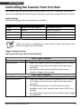
Controlling the Scanner from the Host
The scanner can be controlled from the host system via RS-232C interface. Controlling
can be accomplished by transmitting the following single byte commands to the scanner.
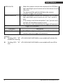
Default Settings
The default settings of the commands are as follows:
ASCII Code Function Byte is Also Called:
0E Hex enable (resumes disable) Shift Out or <Ctrl-N>
0F Hex disable Shift In or <Ctrl-O>
05 Hex power-up re-initialization ENQ or <Ctrl-E>
12 Hex sleep DC2 <Ctrl-R>
14 Hex wake up (resumes sleep) DC4 <Ctrl-T>
When the scanner is disabled, the motor of the scanner will stay on until
the scanner goes into sleep mode.
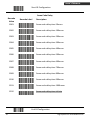
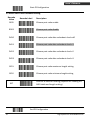
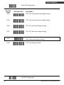
Trigger Command Format
(Only for RS-232C and USB-Virtual COM Port)
Level Trigger Command
Command Description
<ESC>A0<CR> When the scanner receives this command, the CCD/laser
would light up and start scanning barcodes entering its
scan filed.
The light would be switched off when the scanner
receives a trigger off command.
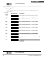
Edge Trigger Command
Command Description
<ESC>A0.mm<CR> When the scanner receives this command, the CCD/laser
would light up and start scanning barcodes entering its
scan field.
The light would remain on until the scanner reads a
barcode or until “mm” period is over (mm=01~60, unit:
second).
The edge trigger command is not controlled by the trigger
off command.

High-Speed Laser Scan Module Series
9
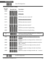
USER’S MANUAL
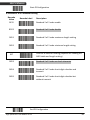
<ESC>A2<CR> When the scanner receives this command, the CCD/laser
light would light up and remain on but the device can only
scan once.
The light would be switched off when the scanner
receives a trigger off command.
<ESC>A2.mm<CR> When the scanner receives this command, the CCD/laser
light would light up and remain on until “mm” period is
over.
If the scanner read a barcode before “mm” period is over,
the light-off countdown would re-start.
The scanner is not controlled by the trigger off command.
Trigger Off Command
Command Description
<ESC>A1<CR> The CCD/laser light would be switched off when the
scanner receives a trigger off command.
Example:
Sending <ESC>“A0”<CR> (0x1b 0x41 0x30 0x0d) to scan module will activate the
module for scanning.
Sending <ESC>“A1”<CR> (0x1b 0x41 0x31 0x0d) to scan module will turn off the
scan.

High-Speed Laser Scan Module Series
10
USER’S MANUAL
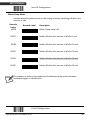
Operation
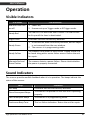
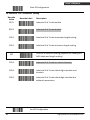
Visible Indicators
LED Status LED Indication
Red and Green LED
are off
1. Power off.
2. Scanner set up as Trigger mode or IR Trigger mode.
Steady Red
The red LED is on when the laser is active. The red LED will
be lit up until the laser is deactivated.
Single Green A barcode has been successfully decoded.
Steady Green
1. A barcode has been successfully decoded, but the object
is not removed from the scan window.
2. The scanner is in programming mode.
Steady Yellow
The scanner has a motor or laser failure. A beep sound is to
be heard along with a motor failure occurs. Return the unit
for repair.
Alternate Red and
Green Flashes
The scanner detects a power failure. Please check whether
the power is properly connected.
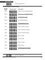
Sound Indicators
The scanner provides audible feedback when it is in operation. The beeps indicate the
status of the scanner.
Beep Indication
One Beep A barcode has been successfully decoded.
Three Consequent Beeps
The scanner has passed the self-test and is operating
properly.
Two Consequent Beeps The scanner is in programming mode.
Continuous Beep Tone This is a failure indication. Return the unit for repair.

High-Speed Laser Scan Module Series
11
USER’S MANUAL
Sleep Mode
After the scanner has been inactive for a specific length of time, the laser and the motor
would automatically turn off and the scanner would enter the sleep mode. The blue LED
would blink as indication.
It takes 2 steps to enter the sleep mode. The first step is the laser switching off after 10
minutes; the second step is the motor switching off after 30 minutes. The time period is
programmable. Please see the Sleep Mode section on the Programming Guide for more
details.
To wake up the scanner, simply place an item in front of the motion detecting area and
move back and forth or left and right.
The scanner includes a motion detector that detects activity in front of the
scan window. The detecting distance is about 10-20cm from the scan
window while in condition with effectiveness of environment lights.
The detecting distance is also programmable.
Position Object Detector
Laser is off when the scanner is in the IR trigger mode. The scanner would automatically
activate the laser and decodes when there is an object presented in the scanning range.
But for the same barcode, the barcode can not read two times in a roll. The scanner
reads only after the barcode is removed over “same code delay” duration and re-enter
the range. (For the setting of same code delay duration time, please refer to the
Programming Guide section.)
The laser will be switched off automatically if no barcode is present for more than 10
seconds. A red light will flash under this circumstance and laser will be turned off until
the next detection.

High-Speed Laser Scan Module Series
12
USER’S MANUAL
Avoid putting objects in front of a reflective background for it might affect the
correctness of this function.
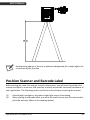
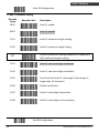
Position Scanner and Barcode Label
Before testing the read rate and get its best performance, you will need to position the
scanner and label in a manner that matches as nearly as possible the actual conditions of
your application. The following points need to be noticed when mounting the scanner:
(1) Avoid straight sunlight or any other bright light source illuminating.
(2) When placing the barcode label, one must be careful not to over tilt, skew and/or
pitch the barcode. (Refer to the drawing below)

High-Speed Laser Scan Module Series
13
USER’S MANUAL
(3) Avoid putting the scanner in a specular reflection position. If the angle between
the scanner and the barcode is between a specular reflection, the laser light will
reflect straight back on the scanner and the internal sensor will be unable to read
any barcodes.
(4) The barcode must be placed within the effective depth of field (D.O.F.) area. The
so-called “Depth of Field” is the effective barcode reading distance for the scanner.
It works like a camera. If the object is placed within the focal range, the image
would appear clearly; if the object is outside the focal range, the image would be
blurred. The D.O.F. of a scanner is determined by the quality and density of
barcodes. Usually for barcodes of shorter length or higher density, the depth of
field is shorter. Moreover, it is better to avoid using depth of field extremes range.
This will prevent moving the barcode often and it easily could be move away from
the reading range.
F
or the best placing position, please refer to the Decode Depth of Field
drawing on the next page.

High-Speed Laser Scan Module Series
14
USER’S MANUAL
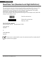
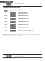
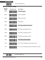
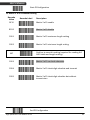
Read Rate Test (Standard and High Definition)
The read rate test can help in determining the optimum position of the scanner. In this
test the scanner continuous to scan and decode a barcode for 500 times and then
calculates the number of those scans that resulted in a good decode. This number,
expressed as a percentage, will be transmitted to the host.
As the factory default, over 93% good decode will get a short beeper sound; under 93%
will get 3 series beeper sound.
Start the read rate test
Perform the read rate test
Read rate = 93%
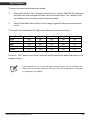
Host data display example:
(Barcode type: code 39. Barcode value: 12345)
12345 93% OK
Code 39
or
12345 80% BAD
Code 39
If the scanner is powered off or reset, the read rate test will not retain and will
need to be set up again.
Page is loading ...
Page is loading ...
Page is loading ...
Page is loading ...
Page is loading ...
Page is loading ...
Page is loading ...
Page is loading ...
Page is loading ...
Page is loading ...
Page is loading ...
Page is loading ...
Page is loading ...
Page is loading ...
Page is loading ...
Page is loading ...
Page is loading ...
Page is loading ...
Page is loading ...
Page is loading ...
Page is loading ...
Page is loading ...
Page is loading ...
Page is loading ...
Page is loading ...
Page is loading ...
Page is loading ...
Page is loading ...
Page is loading ...
Page is loading ...
Page is loading ...
Page is loading ...
Page is loading ...
Page is loading ...
Page is loading ...
Page is loading ...
Page is loading ...
Page is loading ...
Page is loading ...
Page is loading ...
Page is loading ...
Page is loading ...
Page is loading ...
Page is loading ...
Page is loading ...
Page is loading ...
Page is loading ...
Page is loading ...
Page is loading ...
Page is loading ...
Page is loading ...
Page is loading ...
Page is loading ...
Page is loading ...
Page is loading ...
Page is loading ...
Page is loading ...
Page is loading ...
Page is loading ...
Page is loading ...
Page is loading ...
Page is loading ...
Page is loading ...
Page is loading ...
Page is loading ...
Page is loading ...
Page is loading ...
Page is loading ...
Page is loading ...
Page is loading ...
Page is loading ...
Page is loading ...
Page is loading ...
-
 1
1
-
 2
2
-
 3
3
-
 4
4
-
 5
5
-
 6
6
-
 7
7
-
 8
8
-
 9
9
-
 10
10
-
 11
11
-
 12
12
-
 13
13
-
 14
14
-
 15
15
-
 16
16
-
 17
17
-
 18
18
-
 19
19
-
 20
20
-
 21
21
-
 22
22
-
 23
23
-
 24
24
-
 25
25
-
 26
26
-
 27
27
-
 28
28
-
 29
29
-
 30
30
-
 31
31
-
 32
32
-
 33
33
-
 34
34
-
 35
35
-
 36
36
-
 37
37
-
 38
38
-
 39
39
-
 40
40
-
 41
41
-
 42
42
-
 43
43
-
 44
44
-
 45
45
-
 46
46
-
 47
47
-
 48
48
-
 49
49
-
 50
50
-
 51
51
-
 52
52
-
 53
53
-
 54
54
-
 55
55
-
 56
56
-
 57
57
-
 58
58
-
 59
59
-
 60
60
-
 61
61
-
 62
62
-
 63
63
-
 64
64
-
 65
65
-
 66
66
-
 67
67
-
 68
68
-
 69
69
-
 70
70
-
 71
71
-
 72
72
-
 73
73
-
 74
74
-
 75
75
-
 76
76
-
 77
77
-
 78
78
-
 79
79
-
 80
80
-
 81
81
-
 82
82
-
 83
83
-
 84
84
-
 85
85
-
 86
86
-
 87
87
-
 88
88
-
 89
89
-
 90
90
-
 91
91
-
 92
92
-
 93
93


