Page is loading ...

1
SF124
v1.0
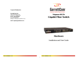
SF124 24-ports switch for 24 IP cameras
Edition: 1 from 06.06.2018
Supercedes the edition: -----------
EN
Features:
Switch 24 ports
24 PoE ports 10/100Mb/s (data transfer
and power supply)
2 ports 10/100/1000 Mb/s (G1/TP, G2/TP ports) (UpLink)
2 ports 10/100/1000Mb/s SFP (G1/SFP, G2/SFP ports)
(UpLink)
30W for each PoE port, supports devices complaint with
the IEEE802.3af/at (PoE+) standard
Supports auto-learning and auto-aging of MAC addresses
(16K size)
LED indication
Additional assembly elements
warranty – 2 year from the production date
Example of use.
1. Technical description.
1.1. General description.
SF124 is a 24-ports PoE switch designed to supply IP cameras operating in IEEE 802.3af/at standard.
Automatic detection of any devices powered in the PoE/PoE+ standard is enabled at the 1 – 8 ports of the switch. The G1/TP
and G2/TP ports is used for connection of another network device via RJ45 connector. The switch is fitted with SFP slots
(marked as G1/SFP and G2/SFP), the use of fiber optic module (GBIC) allows fiber optic transmission.The operating status of
the device (described in the table below) is displayed on the LED display on the front panel.
The PoE technology ensures a network connection and reduces installation costs by eliminating the need to supply a
separate power cable for each device. This method allows supplying other network devices, such as IP phone, wireless access
point or router.

2
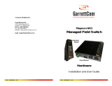
1.2. Block diagram.
Fig. 1. Block diagram.
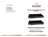
1.3. Description of components and connectors.
Table 1. (see Fig. 2, 3 and 4)
Element no.
(Fig. 2)
Description
[1]
LED indication
[2]
24 x PoE port (1÷24)
[3]
2 x UPLINK ports (G1/TP, G2/TP)
[4]
2 x UPLINK ports (G1/SFP, G2/SFP)
[5]
Power Socket of the AC
[6]
Additional mounting elements
Fig. 2. The front power of the switch.
Fig. 3. Rear panel of the switch.

3
Fig. 4. The view switch'a.
1.4. Technical parameters
Table 2.
Ports
24 x PoE (10/100Mb/s) (RJ-45)
2 x UpLink (10/100/1000Mb/s) (RJ-45)
2 x UpLink (10/100/1000Mb/s) (SFP)
with connection speed auto-negotiation and MDI/MDIX Auto Cross)
PoE power supply
IEEE 802.3af/at (1÷24 ports), 52VDC / 30W at each port *
Used pairs 4/5 (+), 7/8 (-)
Protocols, Standards
IEEE802.3, 802.3u, 802.3x CSMA/CD, TCP/IP
Bandwidth
14,8Gbps
Transmission method
Store-and-Forward
Optical indication of
operation
Switch power supply
Link
PoE Status
Power supply
90 ÷ 264VAC 50/60Hz / 1,3A / 230VAC
Operating conditions
temperature -10°C ÷ 40°C,
relative humidity 5% - 90%, no condensation
Dimensions
W=442, H=44, D=224 [+/- 2mm]
Additional equipment
bracket for Rack 19”
Cable length AC
1,2m
Net/gross weight
3,0 / 3,5kg
Protection class
EN 60950-1:2007
I (first)
Storage temperatur
-20°C ÷ 60°C
Declarations
CE
* The given value of 30W per port is the maximum value. The total power consumption should not exceed 240W when all PoE ports are being used.

4
2. Installation.
2.1. Requirements.
The unit should be mounted in confined spaces, in accordance with the 2nd environmental class, with normal
relative humidity (RH=90% maximum, without condensation) and temperature from -10°C to +40°C. Ensure the free flow
of air around the unit. The PSU shall work in a vertical position that guarantees sufficient convectional air-flow through
ventilating holes of the enclosure.
The switch load balance should be done before installation. The given value of 30W per port is the maximum
value referring to a single output. The total power consumption should not exceed 240W when all PoE ports are being
used. The increased demand for power is particularly evident in the case of cameras with heaters or infrared illuminators -
when launching these features, the power consumption increases rapidly, which may adversely affect the operation of the
switch. As the device is designed for a continuous operation and is not equipped with a power-switch, therefore an appropriate
overload protection in the power supply circuit should be provided. The electrical system shall be made in accordance with
applicable standards and regulations.
2.2. Installation procedure.
1. Connect the 230V AC power supply and turn on the device. The connection should be made with the supplied 3-core
cable with a plug. The place and method of installation of the switch should ensure free air flow around the unit.
2. Connect the camera wires to the RJ45 connectors (sockets RJ45 from 1 to 24).
3. Connect the remaining LAN devices to RJ45 connectors or SFP socket (G1/TP and G1/SFP or G2/TP and G2/SFP)
CAUTION! G1/TP and G1/SFP or G2/TP and G2/SFP connectors can not operate simultaneously!
4. Check the optical indication of switch operation (see Table 3).
Connection schemes

5
3. Operation indication (see table 3)
Table 3. Operation indication
OPTICAL INDICATION OF THE SWITCH's POWER SUPPLY
GREEN LED LIGHT (Power)
Indication of the switch's power
supply
OFF – no power supply of the switch
ON – power supply on, normal operation
OPTICAL INDICATION AT THE PoE PORTS (1÷24)
GREEN LED LIGHT (PoE)
Indication of the PoE power supply
at the RJ45 ports
OFF- no power supply at the RJ45 port (the device is not connected or not compliant with
the IEEE802.3af standard)
ON – supply
Blinking – short-circuit or output overload
YELLOW LED LIGHT (LINK)
The connection status of LAN
devices, 10MB/s or 100Mb/s
and data transmission
OFF- no connection
ON - the device is connected; 10Mb/s or 100Mb/s
Blinking – data transmission
OPTICAL INDICATION AT THE UPLINK PORTS (G1/TP, G2/TP, G1/SFP, G2/SFP)
YELLOW LED
LIGHT (LINK)
No light (OFF) - no connection
ON - device is connected
Blinking – data transmission
CAUTION! The operating status of the G1/TP, G1/SFP, G2/TP and G2/SFP slots is
shown on the LEDs located near the RJ45 connector (see below).
CAUTION! G1/TP and G1/SFP or G2/TP and G2/SFP sockets can not operate
simultaneously.
These are COMBO type sockets.
GREEN LED
LIGHT
(SPEED)
OFF – connection 10Mb/s or 100Mb/s
ON - connection 1000Mb/s
CAUTION! The operating status of the G1/TP, G1/SFP, G2/TP and G2/SFP slots is
shown on the LEDs located near the RJ45 connector (see below).
CAUTION! G1/TP and G1/SFP or G2/TP and G2/SFP sockets can not operate
simultaneously.
These are COMBO type sockets.

6
WEEE LABEL
Waste electrical and electronic equipment must not be disposed of with normal household waste.
According to the European Union WEEE Directive, waste electrical and electronic equipment
should be disposed of separately from normal household waste.
Pulsar
Siedlec 150, 32-744 Łapczyca, Poland
Tel. (+48) 14-610-19-40, Fax. (+48) 14-610-19-50
http:// www.pulsar.pl, www.zasilacze.pl
/