2
68-783-50 Rev. E
03 12
XTRA™ Full Rack Series • Setup Guide (Continued)
Extron Headquarters
+1.800.633.9876 (Inside USA/Canada Only)
Extron USA - West Extron USA - East
+1.714.491.1500 +1.919.863.1794
+1.714.491.1517 FAX +1.919.863.1797 FAX
Extron Europe
+800.3987.6673
(Inside Europe Only)
+31.33.453.4040
+31.33.453.4050 FAX
Extron Asia
+800.7339.8766
(Inside Asia Only)
+65.6383.4400
+65.6383.4664 FAX
Extron Japan
+81.3.3511.7655
+81.3.3511.7656 FAX
Extron China
+4000.398766
Inside China Only
+86.21.3760.1568
+86.21.3760.1566 FAX
Extron Middle East
+971.4.2991800
+971.4.2991880 FAX
Extron Korea
+82.2.3444.1571
+82.2.3444.1575 FAX
Extron India
1800.3070.3777
Inside India Only
+91.80.3055.3777
+91.80.3055.3737 FAX
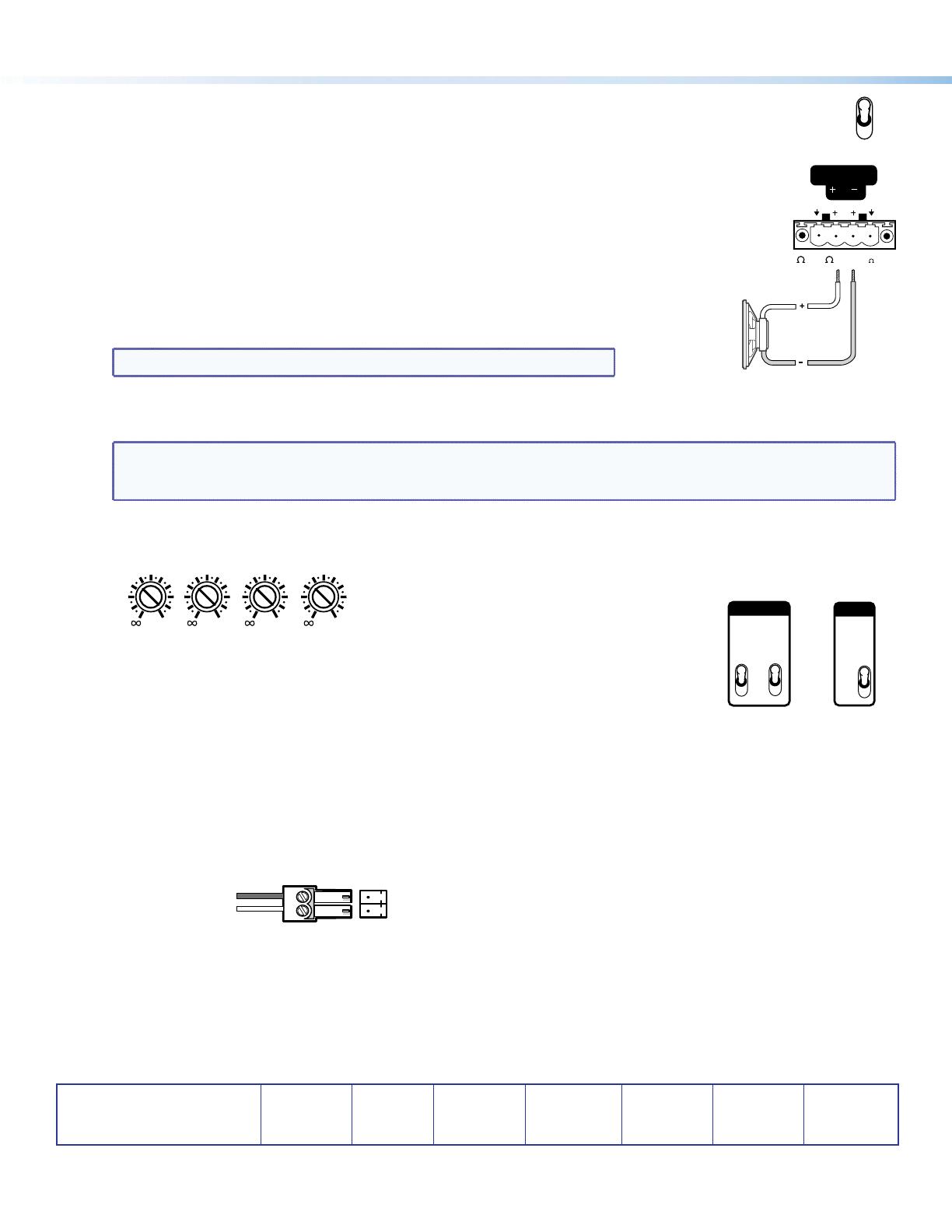
5. Bridge outputs (XPA 2002, XPA 2004, and XPA 4002) — Bridging the output of input 1 (XPA 2002 and XPA 4002)
or inputs 1 and 3 (XPA 2004) doubles the output of those inputs (see “Bridged Mode Output” in the
user guide for further details). The bridge output mode toggle switch is shown at right.
Bridge mode: XPA 2002 and XPA 4002
Bridging takes the signal from input 1 and outputs the combined output of 400 watts (XPA 2002)
or 800 watts (XPA 4002) from the + terminals of output channels 1 and 2 (see the diagram at right).
Toggle the bridged output mode switch up (bridged) or down (unbridged).
Bridge mode: XPA 2004
Bridging takes the signal from input 1 or input 3 or both and outputs the combined
output of 400 watts from the + terminals of output channels 1 and 2 (Bridge A), or
output channels 3 and 4 (Bridge B), or both (see the diagram at right). Toggle the bridged
output mode switch up (bridged) or down (unbridged) for the appropriate input channel.
NOTE: When bridging outputs, the minimum load impedance is 8 ohms.
6. Reconnect all power cords and switch on all other equipment before powering up the power amplifier. The amplifier
must be powered up last. The front panel LED of the amplifier should light green.
NOTE: Adjust the attenuation level to = before powering the amplifier back up in step 6. See “Rear Panel Features
and Operation” in the user guide for details. On some models, this adjustment is referred to as “level”, but
the function is the same, whichever way your product is labeled.
7. Adjust the attenuation level using the rear panel adjustment screws.
12
0
2
4
6
8
10
14
18
26
12
0
2
4
6
8
10
14
12
0
2
4
6
8
10
14
12
0
2
4
6
8
10
14
12
8. Set the high pass filter — Use a small screwdriver to toggle this switch between off
(no filtering) and 80 Hz (default). The XPA 2002-70V, XPA 2002-100V, and XPA 4002-70V
have two switches, one for each output channel. The XPA 2003C-70V and the
XPA 2003C-100V have one switch for the 70 V (XPA 2003C-70V) or 100 V (XPA 2003C-100V)
line distribution output channel (channel 3). Setting the switch to 80 Hz prevents the
saturation of speaker input transformers by low frequency signals (see the diagram at right).
9. If desired, wire a contact closure device to the remote standby connector. Connecting pin 2 to ground (pin 1)
places the amplifier in standby mode. Standby mode turns off all outputs, although the amplifier is still
receiving power.
Use the included 2-pin, 3.5 mm captive screw connector to jumper the pins.
To Contact Closure Port
on Control Device
STANDBY
G
1
2
BRIDGE A
8/4
8 Ohm
(BRIDGE 8 ONLY)
HPF
80 Hz
OFF
3
1
2
HPF
80 Hz
OFF
XPA 2002-70V
XPA 2002-100V
XPA 4002-70V
XPA 2003C-70V
XPA 2003C-100V
© 2012 Extron Electronics All rights reserved. www.extron.com
ON
OFF


