Gigabyte GA-78LMT-USB3 User manual
- Category
- Motherboards
- Type
- User manual
This manual is also suitable for

GA-78LMT-USB3
User's Manual
Rev. 4101
12ME-78LTUB3-4101R

Motherboard
GA-78LMT-USB3
Jul. 27, 2012
Jul. 27, 2012
Motherboard
GA-78LMT-USB3

Copyright
© 2012 GIGA-BYTE TECHNOLOGY CO., LTD. All rights reserved.
The trademarks mentioned in this manual are legally registered to their respective owners.
Disclaimer
Information in this manual is protected by copyright laws and is the property of GIGABYTE.
Changes to the specications and features in this manual may be made by GIGABYTE without
prior notice. No part of this manual may be reproduced, copied, translated, transmitted, or
published in any form or by any means without GIGABYTE's prior written permission.
In order to assist in the use of this product, carefully read the User's Manual.
For product-related information, check on our website at: http://www.gigabyte.com
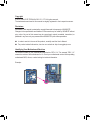
Identifying Your Motherboard Revision
The revision number on your motherboard looks like this: "REV: X.X." For example, "REV: 1.0"
means the revision of the motherboard is 1.0. Check your motherboard revision before updating
motherboard BIOS, drivers, or when looking for technical information.
Example:

- 4 -
Table of Contents
GA-78LMT-USB3 Motherboard Layout ........................................................................... 5
GA-78LMT-USB3 Motherboard Block Diagram ..............................................................6
Chapter 1 Hardware Installation .....................................................................................7
1-1 Installation Precautions ................................................................................... 7
1-2 ProductSpecications ..................................................................................... 8
1-3 Installing the CPU .......................................................................................... 10
1-4 Installing the Memory .....................................................................................11
1-5 Installing an Expansion Card ..........................................................................11
1-6 Back Panel Connectors ................................................................................. 12
1-7 Internal Connectors ....................................................................................... 14
Chapter 2 BIOS Setup ..................................................................................................23
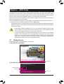
2-1 Startup Screen ............................................................................................... 23
2-2 The Main Menu .............................................................................................. 24
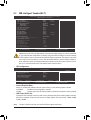
2-3 MB Intelligent Tweaker(M.I.T.) ....................................................................... 25
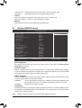
2-4 Standard CMOS Features ............................................................................. 29
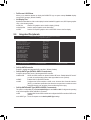
2-5 Advanced BIOS Features .............................................................................. 30
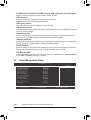
2-6 Integrated Peripherals ................................................................................... 32
2-7 Power Management Setup ............................................................................ 34
2-8 PnP/PCICongurations ................................................................................. 36
2-9 PC Health Status ........................................................................................... 36
2-10 Load Fail-Safe Defaults ................................................................................. 37
2-11 Load Optimized Defaults ............................................................................... 38
2-12 Set Supervisor/User Password ..................................................................... 38
2-13 Save & Exit Setup .......................................................................................... 39
2-14 Exit Without Saving........................................................................................ 39
Chapter 3 Drivers Installation .......................................................................................40
Chapter 4 Appendix ......................................................................................................40
ConguringSATAHardDrive(s) ............................................................................... 40
Regulatory Statements ............................................................................................. 43

- 5 -
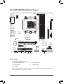
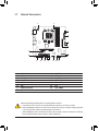
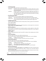
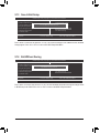
GA-78LMT-USB3 Motherboard Layout
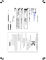
The box contents above are for reference only and the actual items shall depend on the product package you obtain.
The box contents are subject to change without notice.
Box Contents
5
GA-78LMT-USB3 motherboard
5
Motherboard driver disk
5
Two SATA cables
5
User's Manual
5
One IDE cable
5
I/O Shield
KB_MS_USB
CPU_FAN
AM3+
ATX
IDE
GA-78LMT-USB3
F_AUDIO
AUDIO
B_BIOS
DDR3_4
DDR3_2
DDR3_3
DDR3_1
BAT
ATX_12V
SATA2
SATA2
R_USB30
CODEC
M_BIOS
DVI
VGA
HDMI
USB_LAN
PCIEX16
PCIEX1
PCI
F_USB30
F_USB2 F_PANELF_USB1
SYS_FAN
LPTSPDIF_O COM
CLR_CMOS
Realtek
GbE LAN
Etron
EJ168
Etron
EJ168
AMD 760G
AMD SB710
2 3
0 1
5
4
iTE
Super I/O

- 6 -
iTE
Super I/O
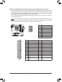
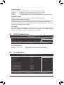
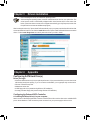
GA-78LMT-USB3 Motherboard Block Diagram
PS/2 KB/Mouse
COM
LPT
LPC
Bus
Line Out (Front Speaker Out)
MIC (Center/Subwoofer
Speaker Out)
Line In (Rear Speaker Out)
CODEC
Fordetailedproductinformation/limitation(s),referto"1-2ProductSpecications."
Hyper Transport 3.0
AMD 760G
CPU CLK+/- (200 MHz)
Dual Channel Memory
PCI Bus
AM3+/AM3 CPU
1 PCI
PCI CLK
(33 MHz)
DDR3 1333+ (O.C.)/1066 MHz
Dual BIOS
8 USB 2.0/1.1
6 SATA 3Gb/s
AMD SB710
PCI Express Bus
PCIe CLK
(100 MHz)
PCIe CLK
(100 MHz)
x1
1 PCI Express x16
x16
1 PCI Express x1
x1 x1
GFX CLK (100 MHz)
HDMI
DVI-D
D-Sub
x1
2 USB 3.0/2.02 USB 3.0/2.0
Etron
EJ168
Etron
EJ168
Realtek
GbE LAN
RJ45
LAN
S/PDIF Out
ATA-133/100/66/33
IDE Channel

- 7 -
Chapter 1 Hardware Installation
1-1 Installation Precautions
The motherboard contains numerous delicate electronic circuits and components which can become
damaged as a result of electrostatic discharge (ESD). Prior to installation, carefully read the user's
manual and follow these procedures:
• Prior to installation, make sure the chassis is suitable for the motherboard.
• Prior to installation, do not remove or break motherboard S/N (Serial Number) sticker or
warranty sticker provided by your dealer. These stickers are required for warranty validation.
• Always remove the AC power by unplugging the power cord from the power outlet before
installing or removing the motherboard or other hardware components.
• When connecting hardware components to the internal connectors on the motherboard, make
sure they are connected tightly and securely.
• When handling the motherboard, avoid touching any metal leads or connectors.
• It is best to wear an electrostatic discharge (ESD) wrist strap when handling electronic
components such as a motherboard, CPU or memory. If you do not have an ESD wrist strap,
keepyourhandsdryandrsttouchametalobjecttoeliminatestaticelectricity.
• Prior to installing the motherboard, please have it on top of an antistatic pad or within an
electrostatic shielding container.
• Before unplugging the power supply cable from the motherboard, make sure the power supply
has been turned off.
• Before turning on the power, make sure the power supply voltage has been set according to
the local voltage standard.
• Before using the product, please verify that all cables and power connectors of your hardware
components are connected.
• To prevent damage to the motherboard, do not allow screws to come in contact with the
motherboard circuit or its components.
• Make sure there are no leftover screws or metal components placed on the motherboard or
within the computer casing.
• Do not place the computer system on an uneven surface.
• Do not place the computer system in a high-temperature environment.
• Turning on the computer power during the installation process can lead to damage to system
components as well as physical harm to the user.
• If you are uncertain about any installation steps or have a problem related to the use of the
product,pleaseconsultacertiedcomputertechnician.

- 8 -
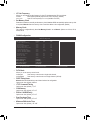
1-2 ProductSpecications
CPU AM3+ Socket:
- AMD AM3+ processor
- AMD AM3 Phenom
™
II processor/ AMD Athlon
™
II processor
(Go to GIGABYTE's website for the latest CPU support list.)
Hyper Transport
Bus
4400 MT/s
Chipset
North Bridge: AMD 760G
South Bridge: AMD SB710
Memory 4 x 1.5V DDR3 DIMM sockets supporting up to 32 GB of system memory
* Due to a Windows 32-bit operating system limitation, when more than 4 GB of
physical memory is installed, the actual memory size displayed will be less than the
size of the physical memory installed.
Dual channel memory architecture
Support for DDR3 1333+ (O.C.)/1066 MHz memory modules
(Go to GIGABYTE's website for the latest supported memory speeds and memory
modules.)
Onboard
Graphics
North Bridge:
- 1 x D-Sub port
- 1 x DVI-D port, supporting a maximum resolution of 1920x1200
* The DVI-D port does not support D-Sub connection by adapter.
- 1 x HDMI port, supporting a maximum resolution of 1920x1200
* Simultaneous output for DVI-D and HDMI is not supported.
Audio Realtek ALC887 codec
High Denition Audio
2/4/5.1/7.1-channel
* To congure 7.1-channel audio, you have to use an HD front panel audio module
and enable the multi-channel audio feature through the audio driver.
Support for S/PDIF Out
LAN 1 x Realtek GbE LAN chip (10/100/1000 Mbit)
Expansion Slots 1 x PCI Express x16 slot, running at x16
1 x PCI Express x1 slot
(All PCI Express slots conform to PCI Express 2.0 standard.)
1 x PCI slot
Storage Interface South Bridge:
- 1 x IDE connector supporting ATA-133/100/66/33 and up to 2 IDE devices
- 6 x SATA 3Gb/s connectors supporting up to 6 SATA 3Gb/s devices
- Support for RAID 0, RAID 1, RAID 10, and JBOD
USB South Bridge:
- Up to 8 USB 2.0/1.1 ports (4 ports on the back panel, 4 ports available through
the internal USB headers)
2 x Etron EJ168 chips:
- Up to 4 USB 3.0/2.0 ports (2 ports on the back panel, 2 ports available through
the internal USB header)

- 9 -
Internal
Connectors
1 x 24-pin ATX main power connector
1 x 8-pin ATX 12V power connector
6 x SATA 3Gb/s connectors
1 x IDE connector
1 x CPU fan header
1 x system fan header
1 x front panel header
1 x front panel audio header
1 x S/PDIF Out header
1 x USB 3.0/2.0 header
2 x USB 2.0/1.1 headers
1 x serial port header
1 x parallel port
1 x Clear CMOS jumper
Back Panel
Connectors
1 x PS/2 keyboard/mouse port
1 x D-Sub port
1 x DVI-D port
1 x HDMI port
2 x USB 3.0/2.0 ports
4 x USB 2.0/1.1 ports
1 x RJ-45 port
3 x audio jacks (Line In/Line Out/Microphone)
I/O Controller iTE I/O Controller Chip
Hardware
Monitor
System voltage detection
CPU/System temperature detection
CPU/System fan speed detection
CPU overheating warning
CPU/System fan fail warning
CPU/System fan speed control
* Whether the CPU/system fan speed control function is supported will depend on the
CPU/system cooler you install.
BIOS 2x16Mbitash
Use of licensed AWARD BIOS
Support for DualBIOS
™
PnP 1.0a, DMI 2.0, SM BIOS 2.4, ACPI 1.0b
Unique Features Support for @BIOS
Support for Q-Flash
Support for Xpress BIOS Rescue
Support for Download Center
Support for Xpress Install
Support for Xpress Recovery2
Support for EasyTune
* Available functions in EasyTune may differ by motherboard model.

- 10 -
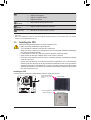
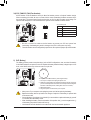
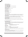
1-3 Installing the CPU
Installing the CPU
Locate the pin one (denoted by a small triangle) of the CPU socket and the CPU.
Read the following guidelines before you begin to install the CPU:
• Make sure that the motherboard supports the CPU.
(Go to GIGABYTE's website for the latest CPU support list.)
• Always turn off the computer and unplug the power cord from the power outlet before installing the
CPU to prevent hardware damage.
• Locate the pin one of the CPU. The CPU cannot be inserted if oriented incorrectly.
• Apply an even and thin layer of thermal grease on the surface of the CPU.
• Do not turn on the computer if the CPU cooler is not installed, otherwise overheating and damage
of the CPU may occur.
• SettheCPUhostfrequencyinaccordancewiththeCPUspecications.Itisnotrecommended
thatthesystembusfrequencybesetbeyondhardwarespecicationssinceitdoesnotmeetthe
standard requirements for the peripherals. If you wish to set the frequency beyond the standard
specications,pleasedosoaccordingtoyourhardwarespecicationsincludingtheCPU,graphics
card, memory, hard drive, etc.
Unique Features Support for Smart Recovery
Support for Auto Green
Support for ON/OFF Charge
Support for Q-Share
Bundled
Software
Norton Internet Security (OEM version)
Operating
System
Support for Microsoft
®
Windows 7/Vista/XP
Form Factor Micro ATX Form Factor; 24.4cm x 24.4cm
* GIGABYTE reserves the right to make any changes to the product specications and product-related information without
prior notice.
* Please visit GIGABYTE's website to check the supported operating system(s) for the software listed in the "Unique
Features" and "Bundled Software" columns.
AM3+/AM3 CPU
A Small Triangle Marking
Denotes CPU Pin One
AM3+ Socket
A Small Triangle Marking
Denotes Pin One of the
Socket

- 11 -
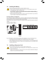
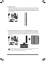
1-4 Installing the Memory
DualChannelMemoryConguration
This motherboard provides four DDR3 memory sockets and supports Dual Channel Technology. After the
memoryisinstalled,theBIOSwillautomaticallydetectthespecicationsandcapacityofthememory.Enabling
Dual Channel memory mode will double the original memory bandwidth.
The four DDR3 memory sockets are divided into two channels and each channel has two memory sockets as
following:
Channel 0: DDR3_2, DDR3_4
Channel 1: DDR3_1, DDR3_3
Due to CPU limitations, read the following guidelines before installing the memory in Dual Channel mode.
1. Dual Channel mode cannot be enabled if only one DDR3 memory module is installed.
2. When enabling Dual Channel mode with two or four memory modules, it is recommended that memory
of the same capacity, brand, speed, and chips be used and installed in the same colored DDR3 sockets
for optimum performance.
Read the following guidelines before you begin to install the memory:
• Make sure that the motherboard supports the memory. It is recommended that memory of the
same capacity, brand, speed, and chips be used.
(Go to GIGABYTE's website for the latest supported memory speeds and memory modules.)
• Always turn off the computer and unplug the power cord from the power outlet before installing the
memory to prevent hardware damage.
• Memory modules have a foolproof design. A memory module can be installed in only one direction.
If you are unable to insert the memory, switch the direction.
1-5 Installing an Expansion Card
Read the following guidelines before you begin to install an expansion card:
• Make sure the motherboard supports the expansion card. Carefully read the manual that came
with your expansion card.
• Always turn off the computer and unplug the power cord from the power outlet before installing an
expansion card to prevent hardware damage.
DualChannelMemoryCongurationsTable
DDR3_4 DDR3_2 DDR3_3 DDR3_1
Two Modules - - DS/SS - - DS/SS
DS/SS - - DS/SS - -
4 Modules DS/SS DS/SS DS/SS DS/SS
(SS=Single-Sided, DS=Double-Sided, "- -"=No Memory)
DDR3_4
DDR3_2
DDR3_3
DDR3_1

- 12 -
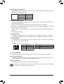
1-6 Back Panel Connectors
USB 2.0/1.1 Port
TheUSB portsupportsthe USB2.0/1.1 specication.Usethis portfor USBdevicessuch asa USB
keyboard/mouse,USBprinter,USBashdriveandetc.
PS/2 Keyboard/Mouse Port
Use this port to connect a PS/2 mouse or keyboard.
D-Sub Port
The D-Sub port supports a 15-pin D-Sub connector. Connect a monitor that supports D-Sub connection
to this port.
DVI-D Port
(Note 1) (Note 2)
TheDVI-DportconformstotheDVI-Dspecicationandsupportsamaximumresolutionof1920x1200
(the actual resolutions supported depend on the monitor being used). Connect a monitor that supports
DVI-D connection to this port.
HDMI Port
(Note 2)
HDMI(High-DenitionMultimediaInterface)isanall-digitalaudio/videointerfacecapableoftransmitting
uncompressed audio/video signals. The HDMI port is HDCP compliant and supports Dolby TrueHD and DTS HD
Master Audio formats. It also supports up to 192KHz/24bit 8-channel LPCM audio output. You can use
this port to connect your HDMI-supported monitor. The maximum supported resolution is 1920x1200, but
the actual resolutions supported are dependent on the monitor being used.
(Note 1) The DVI-D port does not support D-Sub connection by adapter.
(Note 2) Simultaneous output for DVI-D and HDMI is not supported.
• Whenremovingthecableconnectedtoabackpanelconnector,rstremovethecablefromyour
device and then remove it from the motherboard.
• When removing the cable, pull it straight out from the connector. Do not rock it side to side to prevent
an electrical short inside the cable connector.
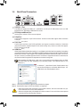
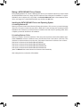
After installing the HDMI device, make sure to set the default sound playback device to HDMI.
(The item name may differ depending on your operating system. The screenshot below is from
Windows 7.)
In Windows 7, select Start>Control Panel>Hardware and
Sound>Sound>Playback, set Realtek HDMI Output - ATI
HDMI Audio to the default playback device.

- 13 -
Activity LED
Connection/
Speed LED
LAN Port
Connection/Speed LED:
State Description
Orange 1 Gbps data rate
Green 100 Mbps data rate
Off 10 Mbps data rate
Activity LED:
State Description
Blinking Data transmission or receiving is occurring
Off No data transmission or receiving is occurring
A.DualDisplayCongurations:
This motherboard provides three video output ports: DVI-D, HDMI, and HDMI. The table below shows the
supporteddualdisplaycongurations.
B.PlaybackofBlu-rayDiscs:
In order to get better playback quality, when playing the Blu-ray discs, refer to the recommended system
requirements (or better) below.
• Memory: Two 1 GB DDR3 1066 MHz memory modules with dual channel mode enabled
• BIOS Setup: At least 256 MB of UMA Frame Buffer Size (refer to Chapter 2, "BIOS Setup," "Advanced
BIOS Features," for more information)
• Playback software: CyberLink PowerDVD 10.0 or later (Note: Please ensure Hardware Acceleration is
enabled.)
• HDCP compliant monitor(s)
Dual Display Combination Supported or Not
D-Sub + DVI-D Yes
D-Sub + HDMI Yes
DVI-D + HDMI No
USB 3.0/2.0 Port
TheUSB3.0portsupportstheUSB3.0specicationandiscompatibletotheUSB2.0/1.1specication.
UsethisportforUSBdevicessuchasaUSBkeyboard/mouse,USBprinter,USBashdriveandetc.
RJ-45 LAN Port
The Gigabit Ethernet LAN port provides Internet connection at up to 1 Gbps data rate. The following
describes the states of the LAN port LEDs.
Line In Jack (Blue)
The default line in jack. Use this audio jack for line in devices such as an optical drive, walkman, etc.
Line Out Jack (Green)
The default line out jack. Use this audio jack for a headphone or 2-channel speaker. This jack can be used
toconnectfrontspeakersina4/5.1/7.1-channelaudioconguration.
Mic In Jack (Pink)
The default Mic in jack. Microphones must be connected to this jack.
Tocongure7.1-channelaudio,youhavetouseanHDfrontpanelaudiomoduleandenablethe
multi-channel audio feature through the audio driver.

- 14 -
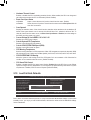
1-7 Internal Connectors
Read the following guidelines before connecting external devices:
• First make sure your devices are compliant with the connectors you wish to connect.
• Before installing the devices, be sure to turn off the devices and your computer. Unplug the power
cord from the power outlet to prevent damage to the devices.
• After installing the device and before turning on the computer, make sure the device cable has
been securely attached to the connector on the motherboard.
1) ATX_12V
2) ATX
3) CPU_FAN
4) SYS_FAN
5) BAT
6) IDE
7) SATA2 0/1/2/3/4/5
8) F_PANEL
9) F_AUDIO
10) SPDIF_O
11) F_USB30
12) F_USB1/F_USB2
13) COM
14) LPT
15) CLR_CMOS
12
5
10
1 3
4
2
6
7
7
149 81113 15

- 15 -
DEBUG
PORT
G.QBOFM
131
2412
ATX
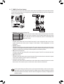
1/2) ATX_12V_2X4/ATX (2x4 12V Power Connector and 2x12 Main Power Connector)
With the use of the power connector, the power supply can supply enough stable power to all the components
onthemotherboard.Beforeconnectingthepowerconnector,rstmakesurethepowersupplyisturned
off and all devices are properly installed. The power connector possesses a foolproof design. Connect the
power supply cable to the power connector in the correct orientation.
The 12V power connector mainly supplies power to the CPU. If the 12V power connector is not connected,
the computer will not start.
To meet expansion requirements, it is recommended that a power supply that can withstand high
power consumption be used (500W or greater). If a power supply is used that does not provide the
required power, the result can lead to an unstable or unbootable system.
ATX:
Pin No. Denition Pin No. Denition
1 3.3V 13 3.3V
2 3.3V 14 -12V
3 GND 15 GND
4 +5V 16 PS_ON (soft On/Off)
5 GND 17 GND
6 +5V 18 GND
7 GND 19 GND
8 Power Good 20 -5V
9 5VSB (stand by +5V) 21 +5V
10 +12V 22 +5V
11 +12V (Only for 2x12-pin
ATX)
23 +5V (Only for 2x12-pin ATX)
12 3.3V (Only for 2x12-pin
ATX)
24 GND (Only for 2x12-pin ATX)
ATX_12V_2X4:
Pin No. Denition
1 GND (Only for 2x4-pin 12V)
2 GND (Only for 2x4-pin 12V)
3 GND
4 GND
5 +12V (Only for 2x4-pin 12V)
6 +12V (Only for 2x4-pin 12V)
7 +12V
8 +12V
DEBUG
PORT
G.QBOFM
ATX_12V_2X4
8 4
5 1

- 16 -
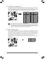
3/4) CPU_FAN/SYS_FAN (Fan Headers)
All fan headers on this motherboard are 4-pin. Most fan headers possess a foolproof insertion design.
When connecting a fan cable, be sure to connect it in the correct orientation (the black connector wire is
the ground wire). The speed control function requires the use of a fan with fan speed control design. For
optimum heat dissipation, it is recommended that a system fan be installed inside the chassis.
• Be sure to connect fan cables to the fan headers to prevent your CPU and system from
overheating. Overheating may result in damage to the CPU or the system may hang.
• Thesefanheadersarenotcongurationjumperblocks.Donotplaceajumpercapontheheaders.
CPU_FAN/SYS_FAN:
Pin No. Denition
1 GND
2 +12V
3 Sense
4 Speed Control
CPU_FAN
SYS_FAN
DEBUG
PORT
G.QBOFM
DEBUG
PORT
G.QBOFM
1
1
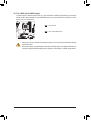
5) BAT (Battery)
Thebatteryprovidespowertokeepthevalues(suchasBIOScongurations,date,andtimeinformation)
in the CMOS when the computer is turned off. Replace the battery when the battery voltage drops to a low
level, or the CMOS values may not be accurate or may be lost.
You may clear the CMOS values by removing the battery:
1. Turn off your computer and unplug the power cord.
2. Gently remove the battery from the battery holder and wait for one minute.
(Or use a metal object like a screwdriver to touch the positive and negative
terminals of the battery holder, making them short for 5 seconds.)
3. Replace the battery.
4. Plug in the power cord and restart your computer.
• Always turn off your computer and unplug the power cord before replacing the battery.
• Replace the battery with an equivalent one. Danger of explosion if the battery is replaced with
an incorrect model.
• Contact the place of purchase or local dealer if you are not able to replace the battery by yourself
or uncertain about the battery model.
• When installing the battery, note the orientation of the positive side (+) and the negative side (-)
of the battery (the positive side should face up).
• Used batteries must be handled in accordance with local environmental regulations.

- 17 -
Pin No. Denition
1 GND
2 TXP
3 TXN
4 GND
5 RXN
6 RXP
7 GND
DEBUG
PORT
G.QBOFM
DEBUG
PORT
G.QBOFM
7
7
1
1
DEBUG
PORT
G.QBOFM
DEBUG
PORT
G.QBOFM
DEBUG
PORT
G.QBOFM
DEBUG
PORT
G.QBOFM
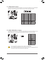
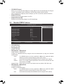
7) SATA2 0/1/2/3/4/5 (SATA 3Gb/s Connectors, Controlled by AMD SB710 South Bridge)
The SATA connectors conform to SATA 3Gb/s standard and are compatible with SATA 1.5Gb/s standard.
Each SATA connector supports a single SATA device. The AMD SB710 controller supports RAID 0, RAID 1,
RAID10,andJBOD.RefertoChapter4,"ConguringSATAHardDrive(s),"forinstructionsonconguring
a RAID array.
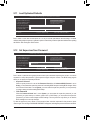
6) IDE (IDE Connector)
The IDE connector supports up to two IDE devices such as hard drives and optical drives. Before attaching
the IDE cable, locate the foolproof groove on the connector. If you wish to connect two IDE devices, remember
to set the jumpers and the cabling according to the role of the IDE devices (for example, master or slave).
(Forinformationaboutconguringmaster/slavesettingsfortheIDEdevices,readtheinstructionsfromthe
device manufacturers.)
SATA2
5
4
SATA2
2 3
0 1
7
1
• ARAID0orRAID1congurationrequiresatleasttwoharddrives.Ifmorethantwoharddrives
are to be used, the total number of hard drives must be an even number.
• ARAID10congurationrequiresfourharddrives.
1
39
2
40

- 18 -
The front panel design may differ by chassis. A front panel module mainly consists of power switch,
reset switch, power LED, hard drive activity LED, speaker and etc. When connecting your chassis
front panel module to this header, make sure the wire assignments and the pin assignments are
matched correctly.
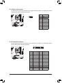
8) F_PANEL (Front Panel Header)
Connect the power switch, reset switch, speaker, chassis intrusion switch/sensor and system status indicator
on the chassis to this header according to the pin assignments below. Note the positive and negative pins
before connecting the cables.
• PW (Power Switch):
Connectstothepowerswitchonthechassisfrontpanel.Youmaycongurethewaytoturnoffyour
system using the power switch (refer to Chapter 2, "BIOS Setup," "Power Management," for more
information).
• Speaker (Speaker):
Connects to the speaker on the chassis front panel. The system reports system startup status by issuing
a beep code. One single short beep will be heard if no problem is detected at system startup. If a problem
is detected, the BIOS may issue beeps in different patterns to indicate the problem.
• HD (Hard Drive Activity LED):
Connects to the hard drive activity LED on the chassis front panel. The LED is on when the hard drive
is reading or writing data.
• RES (Reset Switch):
Connects to the reset switch on the chassis front panel. Press the reset switch to restart the computer
if the computer freezes and fails to perform a normal restart.
• CI (Chassis Intrusion Header):
Connects to the chassis intrusion switch/sensor on the chassis that can detect if the chassis cover has
been removed. This function requires a chassis with a chassis intrusion switch/sensor.
• MSG/PWR (Message/Power/Sleep LED):
System Status LED
S0 On
S1 Blinking
S3/S4/S5 Off
Connects to the power status indicator on the chassis front panel. The LED is
on when the system is operating. The LED keeps blinking when the system
is in S1 sleep state. The LED is off when the system is in S3/S4 sleep state
or powered off (S5).
1
2
19
20
MSG-
PW-
SPEAK+
SPEAK-
MSG+
PW+
Message/Power/
Sleep LED
HD-
RES+
HD+
RES-
Hard Drive
Activity LED
Reset
Switch
Speaker
F_USB30
F_AUDIO(H)
DB_PORT
F_PANEL(NH) F_PANEL
(H61M-D2)
ACPI_CPT
(GA-IVB)
BIOS_PH
(GA-IVB)
SMB_CPT
(GA-IVB)
CLR_CMOS
CI
DIS_ME
GP15_CPT
(GA-IVB)
XDP_CPU
XDP_PCH
(GA-IVB)
TPM
w/housing
Voltage measurement module(X58A-OC)
PCIe power connector (SATA)(X58A-OC)
DIP
123
DIP
123
DIP
123
DIP
123
1
1
1
1
BIOS Switcher (X58A-OC)
PWM Switch (X58A-OC)
M_SATA
PWM Switch (SW1)(X79-UD7)
DIP
1 2 3 4 5
Voltage measurement points(G1.Sniper 3)
BIOS Switcher (SW4)
Power
Switch
Power LED
CI-
CI+
PWR-
PWR+
Chassis Intrusion
Header

- 19 -
9) F_AUDIO (Front Panel Audio Header)
ThefrontpanelaudioheadersupportsIntelHighDenitionaudio(HD)andAC'97audio.Youmayconnect
your chassis front panel audio module to this header. Make sure the wire assignments of the module
connector match the pin assignments of the motherboard header. Incorrect connection between the module
connector and the motherboard header will make the device unable to work or even damage it.
For HD Front Panel Audio: For AC'97 Front Panel Audio:
• The front panel audio header supports HD audio by default.
• Audio signals will be present on both of the front and back panel audio connections simultaneously.
• Some chassis provide a front panel audio module that has separated connectors on each wire
instead of a single plug. For information about connecting the front panel audio module that has
different wire assignments, please contact the chassis manufacturer.
Pin No. Denition
1 MIC2_L
2 GND
3 MIC2_R
4 -ACZ_DET
5 LINE2_R
6 GND
7 FAUDIO_JD
8 No Pin
9 LINE2_L
10 GND
Pin No. Denition
1 MIC
2 GND
3 MIC Power
4 NC
5 Line Out (R)
6 NC
7 NC
8 No Pin
9 Line Out (L)
10 NC
1
2
9
10
10) SPDIF_O (S/PDIF Out Header)
This header supports digital S/PDIF Out and connects a S/PDIF digital audio cable (provided by expansion
cards) for digital audio output from your motherboard to certain expansion cards like graphics cards and
sound cards. For example, some graphics cards may require you to use a S/PDIF digital audio cable for
digital audio output from your motherboard to your graphics card if you wish to connect an HDMI display
to the graphics card and have digital audio output from the HDMI display at the same time.
For information about connecting the S/PDIF digital audio cable, carefully read the manual for your
expansion card.
Pin No. Denition
1 SPDIFO
2 GND
1

- 20 -
12) F_USB1/F_USB2 (USB 2.0/1.1 Headers)
TheheadersconformtoUSB2.0/1.1specication.EachUSBheadercanprovidetwoUSBportsviaan
optional USB bracket. For purchasing the optional USB bracket, please contact the local dealer.
• Do not plug the IEEE 1394 bracket (2x5-pin) cable into the USB header.
• Prior to installing the USB bracket, be sure to turn off your computer and unplug the power cord
from the power outlet to prevent damage to the USB bracket.
10
9
2
1
Pin No. Denition
1 Power (5V)
2 Power (5V)
3 USB DX-
4 USB DY-
5 USB DX+
6 USB DY+
7 GND
8 GND
9 No Pin
10 NC
F_USB30
F_AUDIO(H)
DB_PORT
F_PANEL(NH) F_PANEL
(H61M-D2)
ACPI_CPT
(GA-IVB)
BIOS_PH
(GA-IVB)
SMB_CPT
(GA-IVB)
CLR_CMOS
CI
DIS_ME
GP15_CPT
(GA-IVB)
XDP_CPU
XDP_PCH
(GA-IVB)
TPM
w/housing
Voltage measurement module(X58A-OC)
PCIe power connector (SATA)(X58A-OC)
DIP
123
DIP
123
DIP
123
DIP
123
1
1
1
1
BIOS Switcher (X58A-OC)
PWM Switch (X58A-OC)
M_SATA
PWM Switch (SW1)(X79-UD7)
DIP
1 2 3 4 5
Voltage measurement points(G1.Sniper 3)
BIOS Switcher (SW4)
10
1120
1
11) F_USB30 (USB 3.0/2.0 Header)
TheheaderconformstoUSB3.0/2.0specicationandcanprovidetwoUSBports.Forpurchasingthe
optional 3.5" front panel that provides two USB 3.0/2.0 ports, please contact the local dealer.
Pin No. Denition Pin No. Denition
1 VBUS 11 D2+
2 SSRX1- 12 D2-
3 SSRX1+ 13 GND
4 GND 14 SSTX2+
5 SSTX1- 15 SSTX2-
6 SSTX1+ 16 GND
7 GND 17 SSRX2+
8 D1- 18 SSRX2-
9 D1+ 19 VBUS
10 NC 20 No Pin
Page is loading ...
Page is loading ...
Page is loading ...
Page is loading ...
Page is loading ...
Page is loading ...
Page is loading ...
Page is loading ...
Page is loading ...
Page is loading ...
Page is loading ...
Page is loading ...
Page is loading ...
Page is loading ...
Page is loading ...
Page is loading ...
Page is loading ...
Page is loading ...
Page is loading ...
Page is loading ...
Page is loading ...
Page is loading ...
Page is loading ...
Page is loading ...
-
 1
1
-
 2
2
-
 3
3
-
 4
4
-
 5
5
-
 6
6
-
 7
7
-
 8
8
-
 9
9
-
 10
10
-
 11
11
-
 12
12
-
 13
13
-
 14
14
-
 15
15
-
 16
16
-
 17
17
-
 18
18
-
 19
19
-
 20
20
-
 21
21
-
 22
22
-
 23
23
-
 24
24
-
 25
25
-
 26
26
-
 27
27
-
 28
28
-
 29
29
-
 30
30
-
 31
31
-
 32
32
-
 33
33
-
 34
34
-
 35
35
-
 36
36
-
 37
37
-
 38
38
-
 39
39
-
 40
40
-
 41
41
-
 42
42
-
 43
43
-
 44
44


Gigabyte GA-78LMT-USB3 User manual
- Category
- Motherboards
- Type
- User manual
- This manual is also suitable for
Ask a question and I''ll find the answer in the document
Finding information in a document is now easier with AI
Related papers
-
Gigabyte GA-78LMT-USB3 User manual
-
Gigabyte GA-78LMT-S2PT Owner's manual
-
Gigabyte GA-78LMT-USB3 R2 Owner's manual
-
-
-
-
-
-
-
Other documents
-
PC CHIPS A51G (V7.1) User guide
-
Brainboxes IX-500 Datasheet
-
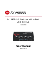 AV Access U3SW24 User manual
-
ASROCK 960GM/U3S3 FX User manual
-
ECS G41T-M9 User manual
-
Contec BX-110n Owner's manual
-
Avocent ESP Multi-Interface Serial Hub SuperSerial Installation guide
-
Equinox Systems ESP-2 OPTO Product Installation Manual
-
-
