Dell OptiPlex 7020 Small Form Factor
Owner's Manual
Regulatory Model: D07S
Regulatory Type: D07S001

Notes, Cautions, and Warnings
NOTE: A NOTE indicates important information that helps you make better use of your computer.
CAUTION: A CAUTION indicates either potential damage to hardware or loss of data and tells you
how to avoid the problem.
WARNING: A WARNING indicates a potential for property damage, personal injury, or death.
Copyright © 2014 Dell Inc. All rights reserved. This product is protected by U.S. and international copyright and
intellectual property laws. Dell
™
and the Dell logo are trademarks of Dell Inc. in the United States and/or other
jurisdictions. All other marks and names mentioned herein may be trademarks of their respective companies.
2014 - 07
Rev. A00

Contents
1 Working on Your Computer................................................................................5
Before Working Inside Your Computer................................................................................................ 5
Turning Off Your Computer..................................................................................................................6
After Working Inside Your Computer................................................................................................... 7
2 Removing and Installing Components............................................................. 8
Recommended Tools............................................................................................................................8
System Overview...................................................................................................................................8
Front, Back, and Inside View........................................................................................................... 8
Removing the Cover........................................................................................................................... 10
Installing the Cover..............................................................................................................................11
Removing the Front Bezel................................................................................................................... 11
Installing the Front Bezel..................................................................................................................... 11
Removing The Expansion Card........................................................................................................... 11
Installing The Expansion Card.............................................................................................................13
Removing the Wireless Local Area Network (WLAN) Card................................................................13
Installing the WLAN Card.................................................................................................................... 14
Removing the Optical Drive................................................................................................................14
Installing the Optical Drive..................................................................................................................15
Removing the Drive Cage................................................................................................................... 15
Installing the Drive Cage..................................................................................................................... 16
Removing the Hard Drive.................................................................................................................... 17
Installing the Hard Drive...................................................................................................................... 17
Removing the Speaker........................................................................................................................ 18
Installing the Speaker.......................................................................................................................... 18
Memory Module Guidelines................................................................................................................19
Removing the Memory........................................................................................................................19
Installing the Memory..........................................................................................................................19
Removing the System Fan...................................................................................................................19
Installing the System Fan.................................................................................................................... 20
Removing the Power Switch...............................................................................................................21
Installing the Power Switch................................................................................................................ 22
Removing the Input/Output (I/O) Panel.............................................................................................22
Installing the Input/Output (I/O) Panel...............................................................................................23
Removing the Power Supply.............................................................................................................. 23
Installing the Power Supply................................................................................................................ 25
Removing the Coin-Cell Battery........................................................................................................ 26
Installing the Coin-Cell Battery.......................................................................................................... 26

Removing the Heat Sink Assembly.....................................................................................................26
Installing the Heat Sink Assembly....................................................................................................... 27
Removing the Processor.....................................................................................................................28
Installing the Processor.......................................................................................................................28
Removing the Intrusion Switch.......................................................................................................... 28
Installing the Intrusion Switch............................................................................................................ 29
Removing the System Board.............................................................................................................. 29
Installing the System Board................................................................................................................ 30
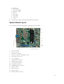
System Board Layout...........................................................................................................................31
3 System Setup....................................................................................................... 33
Boot Sequence....................................................................................................................................33
Navigation Keys................................................................................................................................... 33
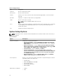
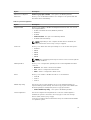
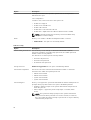
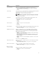
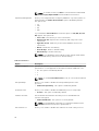
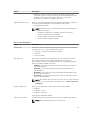
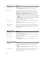
System Setup Options.........................................................................................................................34
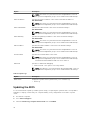
Updating the BIOS ..............................................................................................................................42
Jumper Settings.................................................................................................................................. 43
System and Setup Password...............................................................................................................43
Assigning a System Password and Setup Password.................................................................... 44
Deleting or Changing an Existing System and/or Setup Password............................................ 44
Disabling a System Password....................................................................................................... 45
4 Diagnostics..........................................................................................................46
Enhanced Pre-Boot System Assessment (ePSA) Diagnostics........................................................... 46
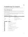
5 Troubleshooting Your Computer....................................................................47
Power LED Diagnostics.......................................................................................................................47
Beep Code...........................................................................................................................................48
Error Messages....................................................................................................................................48
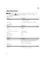
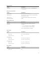
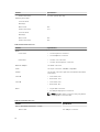
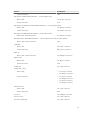
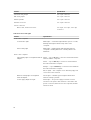
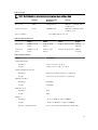
6 Specifications...................................................................................................... 52
7 Contacting Dell................................................................................................... 58

1
Working on Your Computer
Before Working Inside Your Computer
Use the following safety guidelines to help protect your computer from potential damage and to help to
ensure your personal safety. Unless otherwise noted, each procedure included in this document assumes
that the following conditions exist:
• You have read the safety information that shipped with your computer.
• A component can be replaced or--if purchased separately--installed by performing the removal
procedure in reverse order.
WARNING: Disconnect all power sources before opening the computer cover or panels. After you
finish working inside the computer, replace all covers, panels, and screws before connecting to
the power source.
WARNING: Before working inside your computer, read the safety information that shipped with
your computer. For additional safety best practices information, see the Regulatory Compliance
Homepage at
www.dell.com/regulatory_compliance
CAUTION: Many repairs may only be done by a certified service technician. You should only
perform troubleshooting and simple repairs as authorized in your product documentation, or as
directed by the online or telephone service and support team. Damage due to servicing that is
not authorized by Dell is not covered by your warranty. Read and follow the safety instructions
that came with the product.
CAUTION: To avoid electrostatic discharge, ground yourself by using a wrist grounding strap or
by periodically touching an unpainted metal surface, such as a connector on the back of the
computer.
CAUTION: Handle components and cards with care. Do not touch the components or contacts
on a card. Hold a card by its edges or by its metal mounting bracket. Hold a component such as a
processor by its edges, not by its pins.
CAUTION: When you disconnect a cable, pull on its connector or on its pull-tab, not on the cable
itself. Some cables have connectors with locking tabs; if you are disconnecting this type of cable,
press in on the locking tabs before you disconnect the cable. As you pull connectors apart, keep
them evenly aligned to avoid bending any connector pins. Also, before you connect a cable,
ensure that both connectors are correctly oriented and aligned.
NOTE: The color of your computer and certain components may appear differently than shown in
this document.
To avoid damaging your computer, perform the following steps before you begin working inside the
computer.
1. Ensure that your work surface is flat and clean to prevent the computer cover from being scratched.
2. Turn off your computer (see Turning Off Your Computer).
5

CAUTION: To disconnect a network cable, first unplug the cable from your computer and
then unplug the cable from the network device.
3. Disconnect all network cables from the computer.
4. Disconnect your computer and all attached devices from their electrical outlets.
5. Press and hold the power button while the computer is unplugged to ground the system board.
6. Remove the cover.
CAUTION: Before touching anything inside your computer, ground yourself by touching an
unpainted metal surface, such as the metal at the back of the computer. While you work,
periodically touch an unpainted metal surface to dissipate static electricity, which could
harm internal components.
Turning Off Your Computer
CAUTION: To avoid losing data, save and close all open files and exit all open programs before
you turn off your computer.
1. Shut down the operating system:
• In Windows 8:
– Using a touch-enabled device:
a. Swipe in from the right edge of the screen, opening the Charms menu and select
Settings.
b. Select the and then select Shut down
– Using a mouse:
a. Point to upper-right corner of the screen and click Settings.
b. Click the and select Shut down.
• In Windows 7:
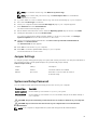
1. Click Start .
2. Click Shut Down.
or
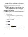
1. Click Start .
2. Click the arrow in the lower-right corner of the Start menu as shown below, and then click
Shut Down..
2. Ensure that the computer and all attached devices are turned off. If your computer and attached
devices did not automatically turn off when you shut down your operating system, press and hold
the power button for about 6 seconds to turn them off.
6

After Working Inside Your Computer
After you complete any replacement procedure, ensure you connect any external devices, cards, and
cables before turning on your computer.
1. Replace the cover.
CAUTION: To connect a network cable, first plug the cable into the network device and then
plug it into the computer.
2. Connect any telephone or network cables to your computer.
3. Connect your computer and all attached devices to their electrical outlets.
4. Turn on your computer.
5. If required, verify that the computer works correctly by running the Dell Diagnostics.
7

2
Removing and Installing Components
This section provides detailed information on how to remove or install the components from your
computer.
Recommended Tools
The procedures in this document may require the following tools:
• Small flat-blade screwdriver
• Phillips screwdriver
• Small plastic scribe
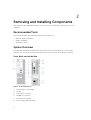
System Overview
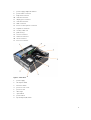
The figure below displays the inside view of the Small Form Factor after the base cover has been
removed. The call outs show the names and the layout of the components inside the computer.
Front, Back, and Inside View
Figure 1. Front and Back View
1. power button or power light
2. flex bay
3. microphone connector
4. headphone connector
5. hard-drive activity light
6. power-supply diagnostic light
8

7. power-supply diagnostic button
8. power cable connector
9. keyboard connector
10. USB 2.0 connector
11. display port connector
12. USB 3.0 connector
13. VGA connector
14. line-in or microphone connector
15. expansion-card slots
16. security-cable slot
17. padlock ring
18. mouse connector
19. network connector
20. serial connector
21. line-out connector
Figure 2. Inside View
1. power supply
2. PCI Express Card
3. intrusion switch
4. processor-fan cover
5. processor fan
6. drive cage
7. optical drive
8. power switch
9. input/output (I/O) Panel
9

1. memory module 2. speaker
3. front bezel 4. system fan
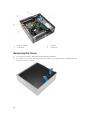
Removing the Cover
1. Follow the procedures in Before Working Inside Your Computer.
2. Pull-up the cover-release latch and lift the cover. Lift the cover upward to a 45–degree angle and
remove it from the computer.
10

Installing the Cover
1. Place the cover on the chassis.
2. Press down on the cover till it clicks into place.
3. Follow the procedures in After Working Inside Your Computer.
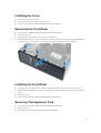
Removing the Front Bezel
1. Follow the procedures in Before Working Inside Your Computer.
2. Remove the cover.
3. Pry the front bezel retention clips away from the chassis.
4. Rotate the bezel away from the computer to release the hooks on the opposite edge of the bezel
from the chassis. Then, lift the chassis and remove the front bezel from the computer.
Installing the Front Bezel
1. Insert the hooks along the bottom edge of the front bezel into the slots on the chassis front.
2. Push the bezel toward the computer to engage the front bezel retention clips until they click into
place.
3. Install the cover.
4. Follow the procedures in After Working Inside Your Computer.
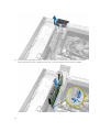
Removing The Expansion Card
1. Follow the procedures in Before Working Inside Your Computer.
2. Remove the cover
3. Rotate the release tab on the card-retention latch upward.
11

4. Pull the release lever away from the expansion card until you release the securing tab from the dent
in the card. Then, ease the card up and out of its connector and remove it from the computer.
12

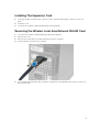
Installing The Expansion Card
1. Insert the expansion card into the connector on the system board and press down to secure it in
place.
2. Install the cover
3. Follow the procedures in After Working Inside Your Computer.
Removing the Wireless Local Area Network (WLAN) Card
1. Follow the procedures in Before Working Inside Your Computer.
2. Remove the cover.
3. Remove the screws that secure the antenna puck to the computer.
4. Pull the antenna puck from the computer.
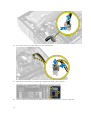
5. Press the blue tab and lift the latch outwards. Lift and remove the WLAN card from the connector on
the system board.
13

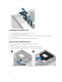
Installing the WLAN Card
1. Place the WLAN card on the connector and press down.
2. Press the latch to secure the WLAN card.
3. Place the antenna puck on the connector and tighten the screws that secure it to the computer.
4. Install the cover.
5. Follow the procedures in After Working Inside Your Computer.
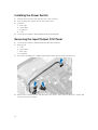
Removing the Optical Drive
1. Follow the procedures in Before Working Inside Your Computer.
2. Remove the cover.
3. Disconnect the data and power cables from the back of the optical drive.
4. Lift the tab and slide the optical drive out to remove it from the computer.
5. Flex the optical-drive bracket and then lift the optical drive from the bracket
14

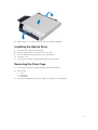
6. Repeat steps 3 to 5 to remove the second optical drive (if available).
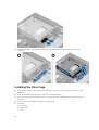
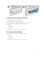
Installing the Optical Drive
1. Insert the optical drive into the bracket.
2. Slide the optical drive to insert it into the drive cage.
3. Connect the data and power cables to the optical drive.
4. Install the cover.
5. Follow the procedures in After Working Inside Your Computer.
Removing the Drive Cage
1. Follow the procedures in Before Working Inside Your Computer.
2. Remove the:
a. cover
b. front bezel
c. optical drive
3. Disconnect the data and the power cables from the back of the hard drive.
15

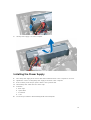
4. Slide the blue drive-cage handle toward unlock position and lift the hard drive cage from the
computer.
Installing the Drive Cage
1. Place the drive cage on the edge of the computer to allow access to the cable connectors on the
hard drive.
2. Connect the data and power cables to the back of the hard drive.
3. Flip over the drive cage and insert it into the chassis. The drive cage tabs are secured by the slots in
the chassis.
4. Slide the drive-cage handle toward the locked position.
5. Install the:
a. front bezel
b. optical drive
c. cover
16

6. Follow the procedures in After Working Inside Your Computer.
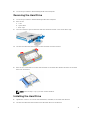
Removing the Hard Drive
1. Follow the procedures in Before Working Inside Your Computer.
2. Remove the:
a. cover
b. optical drive
c. drive cage
3. Press the retention clips inwards and slide the hard-drive bracket out from the drive cage.
4. Flex the hard-drive bracket and remove the hard drive from the bracket.
5. Remove the screws that secure the mini hard drive to the hard-drive bracket and remove the hard
drive from its bracket.
NOTE: Perform step 5 only if you have a mini hard drive.
Installing the Hard Drive
1. Tighten the screws to secure the mini hard drive (if available) to the hard-drive bracket.
2. Flex the hard-drive bracket and then insert the hard drive into the bracket.
17

3. Slide the hard-drive bracket into the drive cage.
4. Install the:
a. drive cage
b. optical drive
c. cover
5. Follow the procedures in After Working Inside Your Computer.
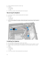
Removing the Speaker
1. Follow the procedures in Before Working Inside Your Computer.
2. Remove the:
a. cover
b. optical drive
c. drive cage
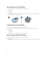
3. Disconnect the speaker cable from the system board and release it from the securing tab inside the
chassis. Press the speaker-securing tab, and slide the speaker towards the right of the computer to
release it.
Installing the Speaker
1. Place the speaker at the appropriate location on the chassis.
2. Press the speaker-securing tab and slide the speaker towards the left of the computer to secure it.
3. Guide the speaker cable through the securing tab and connect the speaker cable to the system
board.
4. Install the:
a. drive cage
b. optical drive
c. cover
5. Follow the procedures in After Working Inside Your Computer.
18

Memory Module Guidelines
To ensure optimal performance of your computer, observe the following general guidelines when
configuring your system memory:
• Memory modules of different sizes can be mixed (for example, 2 GB and 4 GB). But, all populated
channels must have identical configurations.
• Memory modules must be installed beginning with the first socket.
NOTE: The memory sockets in your computer may be labeled differently depending on the
hardware configuration. For example, A1, A2 or 1,2,3.
• If the quad-rank memory modules are mixed with single or dual-rank modules, the quad-rank
modules must be installed in the sockets with the white release levers.
• If memory modules with different speeds are installed, they operate at the speed of the slowest
installed memory modules.
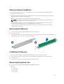
Removing the Memory
1. Follow the procedures in Before Working Inside Your Computer.
2. Remove the cover.
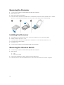
3. Press down on the memory retaining tabs on each side of the memory modules, and lift the memory
modules out of the connectors on the system board.
Installing the Memory
1. Align the notch on the memory-card with the tab in the system-board connector.
2. Press down on the memory module until the release tabs spring back to secure them in place.
3. Install the cover.
4. Follow the procedures in After Working Inside Your Computer.
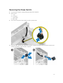
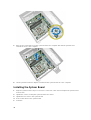
Removing the System Fan
1. Follow the procedures in Before Working Inside Your Computer.
2. Remove
a. cover
b. optical drive
c. drive cage
d. front bezel
19

3. Disconnect the system-fan cable from the system board.
4. Pry and remove the system fan away from the grommets securing it to the front of the computer.
Then, press the grommets inward along the slots and pass through the chassis.
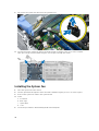
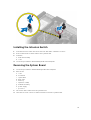
Installing the System Fan
1. Place the system-fan in the chassis.
2. Pass the grommets through the chassis and slide outward along the groove to secure it in place.
3. Connect the system-fan cable to the system board.
4. Install:
a. front bezel
b. drive cage
c. optical drive
d. cover
5. Follow the procedures in After Working Inside Your Computer.
20
Page is loading ...
Page is loading ...
Page is loading ...
Page is loading ...
Page is loading ...
Page is loading ...
Page is loading ...
Page is loading ...
Page is loading ...
Page is loading ...
Page is loading ...
Page is loading ...
Page is loading ...
Page is loading ...
Page is loading ...
Page is loading ...
Page is loading ...
Page is loading ...
Page is loading ...
Page is loading ...
Page is loading ...
Page is loading ...
Page is loading ...
Page is loading ...
Page is loading ...
Page is loading ...
Page is loading ...
Page is loading ...
Page is loading ...
Page is loading ...
Page is loading ...
Page is loading ...
Page is loading ...
Page is loading ...
Page is loading ...
Page is loading ...
Page is loading ...
Page is loading ...
-
 1
1
-
 2
2
-
 3
3
-
 4
4
-
 5
5
-
 6
6
-
 7
7
-
 8
8
-
 9
9
-
 10
10
-
 11
11
-
 12
12
-
 13
13
-
 14
14
-
 15
15
-
 16
16
-
 17
17
-
 18
18
-
 19
19
-
 20
20
-
 21
21
-
 22
22
-
 23
23
-
 24
24
-
 25
25
-
 26
26
-
 27
27
-
 28
28
-
 29
29
-
 30
30
-
 31
31
-
 32
32
-
 33
33
-
 34
34
-
 35
35
-
 36
36
-
 37
37
-
 38
38
-
 39
39
-
 40
40
-
 41
41
-
 42
42
-
 43
43
-
 44
44
-
 45
45
-
 46
46
-
 47
47
-
 48
48
-
 49
49
-
 50
50
-
 51
51
-
 52
52
-
 53
53
-
 54
54
-
 55
55
-
 56
56
-
 57
57
-
 58
58


Ask a question and I''ll find the answer in the document
Finding information in a document is now easier with AI