Page is loading ...

USER'S MANUAL
CAUTION
Read all precautions and instruc
-
tions in this manual before using
this equipment. Save this manual
for future reference.
Serial Number
Decal
Model No. 30704.0
Serial No.
Write the serial number in the space
above for reference.
QUESTIONS?
As a manufacturer, we are com-
mitted to providing complete
customer satisfaction. If you
have questions, or if parts are
damaged or missing, PLEASE
DO NOT CONTACT THE STORE.
For assistance, contact our
Customer Service Department.
CALL TOLL-FREE:
1-888-936-4266
Mon.–Fri., 8:00 until 17:00 EST
(excluding holidays)
OR E-MAIL US:
www.proform.com
Visit our website at
Visit our website at
www.nordictrack.com
Visit our website at
www.healthrider.com
Visit our website at

TABLE OF CONTENTS
WARNING DECAL PLACEMENT . . . . . . . . . . . . . . . . . . . . . . . . . . . . . . . . . . . . . . . . . . . . . . . . . . . . . . . . . . . . . .2
I
MPORTANT PRECAUTIONS . . . . . . . . . . . . . . . . . . . . . . . . . . . . . . . . . . . . . . . . . . . . . . . . . . . . . . . . . . . . . . . . .3
BEFORE YOU BEGIN . . . . . . . . . . . . . . . . . . . . . . . . . . . . . . . . . . . . . . . . . . . . . . . . . . . . . . . . . . . . . . . . . . . . . . .6
ASSEMBLY . . . . . . . . . . . . . . . . . . . . . . . . . . . . . . . . . . . . . . . . . . . . . . . . . . . . . . . . . . . . . . . . . . . . . . . . . . . . . . .7
OPERATION AND ADJUSTMENT . . . . . . . . . . . . . . . . . . . . . . . . . . . . . . . . . . . . . . . . . . . . . . . . . . . . . . . . . . . .14
HOW TO FOLD AND MOVE THE TREADMILL . . . . . . . . . . . . . . . . . . . . . . . . . . . . . . . . . . . . . . . . . . . . . . . . . .27
TROUBLESHOOTING . . . . . . . . . . . . . . . . . . . . . . . . . . . . . . . . . . . . . . . . . . . . . . . . . . . . . . . . . . . . . . . . . . . . . .29
EXERCISE GUIDELINES . . . . . . . . . . . . . . . . . . . . . . . . . . . . . . . . . . . . . . . . . . . . . . . . . . . . . . . . . . . . . . . . . . .32
PART LIST . . . . . . . . . . . . . . . . . . . . . . . . . . . . . . . . . . . . . . . . . . . . . . . . . . . . . . . . . . . . . . . . . . . . . . . . . . . . . . .34
EXPLODED DRAWING . . . . . . . . . . . . . . . . . . . . . . . . . . . . . . . . . . . . . . . . . . . . . . . . . . . . . . . . . . . . . . . . . . . . .36
ORDERING REPLACEMENT PARTS . . . . . . . . . . . . . . . . . . . . . . . . . . . . . . . . . . . . . . . . . . . . . . . . . .Back Cover
LIMITED WARRANTY . . . . . . . . . . . . . . . . . . . . . . . . . . . . . . . . . . . . . . . . . . . . . . . . . . . . . . . . . . . . . . .Back Cover
NordicTrack is a registered trademark of ICON IP, Inc.
2
50%
The decals shown here have been applied in the loca-
tions shown.
If a decal is missing or illegible, call the
telephone number on the front cover of this manual
and request a free replacement decal. Apply the
decal in the location shown. Note: The decals may not
be shown at actual size.
WARNING DECAL PLACEMENT

1. Before beginning any exercise program, con-
sult your physician. This is especially impor-
tant for persons over the age of 35 or per-
sons with pre-existing health problems.
2. It is the responsibility of the owner to ensure
that all users of this treadmill are adequately
informed of all warnings and precautions.
3. Use the treadmill only as described.
4. Place the treadmill on a level surface, with at
least 8 ft. (2.4 m) of clearance behind it and
2 ft. (0.6 m) on each side. Do not place the
treadmill on any surface that blocks air open-
ings. To protect the floor or carpet from dam-
age, place a mat under the treadmill.
5. Keep the treadmill indoors, away from mois-
ture and dust. Do not put the treadmill in a
garage or covered patio, or near water.
6. Do not operate the treadmill where aerosol
products are used or where oxygen is being
administered.
7. Keep children under the age of 12 and pets
away from the treadmill at all times.
8.
The treadmill should not be used by persons
weighing more than 350 lbs (159 kg).
9. Never allow more than one person on the
treadmill at a time.
10. Wear appropriate exercise clothes when
using the treadmill. Do not wear loose clothes
that could become caught in the treadmill.
Athletic support clothes are recommended for
both men and women.
Always wear athletic
shoes. Never use the treadmill with bare feet,
wearing only stockings, or in sandals.
11.
When connecting the power cord (see page 14),
plug the power cord into a surge suppressor
(not included) and plug the surge suppressor
into a grounded circuit capable of carrying 15
or more amps. No other appliance should be on
the same circuit. Do not use an extension cord.
12. Use only a single-outlet surge suppressor that
meets all of the specifications described on
page 14. To purchase a surge suppressor call
the toll-free telephone number on the front
cover of this manual.
13. Failure to use a properly functioning surge
suppressor could result in damage to the con-
trol system of the treadmill. If the control sys-
tem is damaged, the walking belt may change
speed, accelerate, or stop unexpectedly,
which may result in a fall and serious injury.
14. Keep the power cord and the surge suppres-
sor away from heated surfaces.
15. Never move the walking belt while the power
is turned off. Do not operate the treadmill if
the power cord or plug is damaged, or if the
treadmill is not working properly. (See
TROUBLESHOOTING on page 29 if the tread-
mill is not working properly.)
16. Read, understand, and test the emergency
stop procedure before using the treadmill (see
HOW TO TURN ON THE POWER on page 16).
17.
Never start the treadmill while you are stand-
ing on the walking belt. Always hold the
handrails while using the treadmill.
18. The treadmill is capable of high speeds.
Adjust the speed in small increments to avoid
sudden jumps in speed.
19. The pulse sensor is not a medical device.
Various factors, including the user's move-
ment, may affect the accuracy of heart rate
readings. The pulse sensor is intended only
as an exercise aid in determining heart rate
trends in general.
20.
Never leave the treadmill unattended while it
is running. Always remove the key, unplug the
power cord, and switch the reset/off circuit
breaker to the off position when the treadmill
is not in use. (See the drawing on page 6 for
the location of the reset/off circuit breaker.)
WARNING: To reduce the risk of serious injury, read all important precautions and in-
structions in this manual and all warnings on your treadmill before using your treadmill. ICON as-
sumes no responsibility for personal injury or property damage sustained by or through the use of
this product.
IMPORTANT PRECAUTIONS
3

4
21. Do not attempt to raise, lower, or move the
t
readmill until it is properly assembled. (See
A
SSEMBLY on page 7, and HOW TO FOLD
AND MOVE THE TREADMILL on page 27.) You
must be able to safely lift 45 lbs. (20 kg) to
raise, lower, or move the treadmill.
22. Do not change the incline of the treadmill by
placing objects under the treadmill.
23. When folding or moving the treadmill, make
sure that the frame is held securely by the pin
on the latch knob.
24. Inspect and properly tighten all parts of the
treadmill regularly.
25. Never insert or drop any object into any
opening.
26. DANGER: Always unplug the power
cord immediately after use, before cleaning
the treadmill, and before performing the main-
tenance and adjustment procedures de-
scribed in this manual. Never remove the
motor hood unless instructed to do so by an
authorized service representative. Servicing
other than the procedures in this manual
should be performed by an authorized service
representative only.
27. The treadmill is intended for in-home use
only. Do not use the treadmill in any commer-
cial, rental, or institutional setting.
28. If an outside antenna or cable system is con-
nected, be sure that the antenna or cable sys-
tem is grounded to provide some protection
against voltage surges and built-up static
charges. Section 810 of the National
Electrical Code, ANSI/NFPA No. 70-1984, pro-
vides information with respect to proper
grounding of the mast and supporting struc-
ture, grounding of the lead-in wire to an an-
tenna discharge unit, size of grounding con
-
ductors, location of antenna discharge unit,
connection to grounding electrodes, and re-
quirements for the grounding electrode.
29. An outside antenna system should not be lo-
c
ated in the vicinity of overhead power lines
o
r other electric light or power circuits, or
where it can fall into such power lines or cir-
cuits. When installing an outside antenna sys-
tem, extreme care should be taken to keep
f
rom touching such power lines or circuits, as
contact with them might be fatal.
30. To reduce the risk of electric shock, do not re-
move the cover or the back of the television.
There are no user serviceable parts inside.
Refer servicing to qualified service personnel.
31. Upon completion of any service or repairs to
the treadmill or the television, ask the service
technician to perform safety checks to con-
firm that the unit is in proper operating con-
dition.
• Use No. 10 AWG (5.3mm
2
) copper, No. 8
AWG (8.4mm
2
) aluminum, No. 17 AWG
(1.0mm
2
) copper-clad steel or bronze wire,
or larger as a ground wire.
• Secure an antenna lead-in and ground wires
to the house with stand-off insulators
spaced from 4 to 6 feet (1.22 to 1.83 m)
apart.
• Mount an antenna discharge unit as close
as possible to where the lead-in enters the
house.
• Use a jumper wire not smaller than No. 6
AWG (13.3mm
2
) copper, or the equivalent
when a separate antenna-grounding elec-
trode is used. See NEC Section 810-21 (j).
Note to CATV system installer: This reminder is
provided to call the CATV system installer’s at
-
tention to Article 820-40 of the NEC that provides
guidelines for proper grounding and, in particu-
lar, specifies that the cable ground shall be con-
nected to the grounding system of the building,
as close to the point of cable entry as practical.
SAVE THESE INSTRUCTIONS

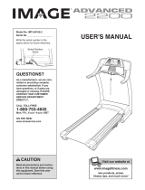
5
Power Lines
Ground
Clamps
Ground
Clamps
Ground
Clamp
Bonding
Jumper
Standoff
Insulators
Antenna
L
ead-in Wire
Ground Wire
Ground
W
ire
A
ntenna
Discharge Unit
T
o External Antenna
Terminal of Treadmill
Mast
Service
Entrance
Equipment
Power Service Grounding
Electrode System (e.g.
Interior Metal Water Pipe)
Service
E
ntrance
Conductors
Optional Antenna Grounding Electrode Driven 8
Feet (2.44m) Into The Earth (If Required By Local
Codes). See NEC Section 810–21 (f).

6
Thank you for selecting the revolutionary NordicTrack
®
V
IEWPOINT 3000 treadmill. The VIEWPOINT 3000
treadmill offers a selection of features designed to
make your workouts at home more enjoyable and ef-
fective. And when you’re not exercising, the unique
V
IEWPOINT 3000 treadmill can be folded up, requiring
less than half the floor space of other treadmills.
For your benefit, read this manual carefully before
using the treadmill
. If you have questions after read-
ing this manual, please see the front cover of this man-
u
al. To help us assist you, note the product model
number and serial number before contacting us. The
model number and the location of the serial number
decal are shown on the front cover of this manual.
Before reading further, please familiarize yourself with
the parts that are labeled in the drawing below.
BEFORE YOU BEGIN
Handrail
Console/Television
Fan
Key/Clip
Reset/Off
Circuit Breaker
Walking Belt
Foot Rail
Power Cord
Cushioned Walking Platform
Rear Roller
Adjustment Bolts
Accessory Tray
Pulse Sensor

7
1. Make sure that the power cord is unplugged.
With the help of a second person, carefully tip
the treadmill onto its side as shown. Partially fold
the Frame (55) so that the treadmill is more sta-
ble. Do not fully fold the Frame until the
treadmill is completely assembled.
Insert an Extension Leg (97) into the indicated
bracket on the base of the Uprights (85). Make
sure that the Extension Leg is turned so the Base
Pad (81) is on the side shown. If necessary, use
a rubber mallet to align the holes in the
Extension Leg with the holes in the bracket.
Attach the Extension Leg (97) with two Extension
Leg Bolts (87), two 5/16" Star Washers (110),
and two Extension Leg Nuts (91) as shown.
Firmly tighten the Extension Leg Bolts.
ASSEMBLY
A
ssembly requires two persons.
S
et the treadmill in a cleared area and remove all packing materials.
D
o not
dispose of the packing materials until assembly is completed.
Note: The underside of the treadmill walking belt is coated with high-performance lubricant. During shipping, a
small amount of lubricant may be transferred to the top of the walking belt or the shipping carton. This is a normal
condition and does not affect treadmill performance. If there is lubricant on top of the walking belt, simply wipe off
the lubricant with a soft cloth and a mild, non-abrasive cleaner.
Assembly requires the included hex key and your own Phillips screwdriver , rubber
mallet and adjustable wrench . For help identifying the assembly hardware, see the
drawings below.
The number following the parentheses is the quantity needed for assembly. Note: If a part is
not in the parts bag, check to see if it has been preassembled. To avoid damaging plastic parts, do not
use power tools for assembly. Extra hardware may be included.
123)–2
1/2” Silver Screw
(48)–1
3/4” Tek Screw (58)–4
3
3/4" Screw (7)–6
1" Tek Screw (82)–8
Washer (96)–8
Extension Leg Bolt (87)–4
5/16" Star
Washer (110)–4
Extension Leg
Nut (91)–4
E
3/8" Star
Washer (67)–4
Nut (20)–2
Base Cover Screw (63)–4
Console Bolt (72)–4
Latch Bolt (109)–2
85
Bracket
81
55
87
91
1
110
97

8
2. Attach two Base Pads (81) to the base of the
Uprights (85) in the indicated locations with two
1
" Tek Screws (82). Note: One replacement Base
Pad may be included. Use the Base Pad to re-
p
lace any Base Pad that becomes worn.
85
81
8
2
82
2
3. With the help of a second person, carefully tip
the treadmill onto its other side as shown.
Partially fold the Frame (55) so that the treadmill
is more stable.
Do not fully fold the Frame
until the treadmill is completely assembled.
Insert the other Extension Leg (97) into the indi-
cated bracket on the base of the Uprights (85).
Attach the Extension Leg (97) with two Extension
Leg Bolts (87), two 5/16" Star Washers (110),
and two Extension Leg Nuts (91) as shown.
Firmly tighten the Extension Leg Bolts.
87
110
Bracket
85
91
97
55
3
4. Attach two Base Pads (81) to the base of the
Uprights (85) in the indicated locations with two
1" Tek Screws (82).
With the help of a second person, carefully tip
the treadmill down so that all four Base Pads
(81) are resting on the floor and the Uprights
(85) are in the vertical position.
81
82
82
85
4
81
81

9
6. Raise the Frame (55) to the position shown.
Have a second person hold the Frame until this
step is completed.
Remove the plastic ties from the ends of the
Latch Assembly (76). Orient the Latch Assembly
so that the large barrel and the knob are in the
positions shown; make sure that all the holes are
aligned as shown in the inset drawings. Attach
the lower end of the Latch Assembly to the
bracket in the center of the Uprights (85) with a
Latch Bolt (109) and a Nut (20).
Attach the upper end of the Latch Assembly (76)
to the bracket on the Frame (55) with a Latch
Bolt (109) and a Nut (20). Note: It may be neces-
sary to move the Frame back and forth to align
the Latch Assembly with the bracket.
Lower the Frame (55) (see HOW TO LOWER
THE TREADMILL FOR USE on page 28).
76
20
20
Large
Barrel
85
109
55
6
109
Knob
Top
Bottom
Holes
Holes
7. Identify the Left Base Cover (88), which has
cutouts in the locations shown. Slide the Left
Base Cover onto the left Upright (85). Then, slide
the Right Base Cover (86) onto the right Upright.
Identify the Left Upright Sleeve (77) and the Right
Upright
Sleeve
(9). Slide the Upright
Sleeves
onto
the Uprights (85) as shown.
88
77
86
9
85
85
Left
Right
Cutouts
7
5. Identify the Latch Assembly (76). Make sure that
t
he sleeve has been slid over hole 1 and that the
latch knob is locked into hole 1.
Pull on the
sleeve to make sure it is locked into place.
N
ext, make sure that the latch knob is locked
into hole 2. If it is not, pull out the tube until you
see hole 2 and then slide the tube back in until
the latch knob locks into hole 2.
5
Latch Knob
Sleeve
H
ole 1
Hole 2
Tube
76

10
10. Attach the console assembly to the Uprights
(85) with four Console Bolts (72) and four 3/8"
Star Washers (67) (only one side is shown).
Start all four Console Bolts and then tighten
them.
67
72
85
Console
Assembly
10
9. Remove the band securing the TV Cable (112) to
the left Upright (85). Connect the TV Cable to
the cable extending from the console assembly.
Then, insert the TV Cable into the left Upright.
Next, insert the brackets on the Handrails (70)
into the left Upright (85) and the right Upright
(not shown).
Make sure that no wires are
pinched.
70
Bracket
112
85
Console
Assembly
9
8. Remove the band securing the Upright Wire
H
arness (73) to the right Upright (85). Have a
second person hold the console assembly near
the right Upright.
Connect the Upright Wire Harness (73) to the wire
harness on the console assembly.
Make sure to
connect the connectors properly (see the
i
nset drawing). The connectors should slide
together easily and snap into place. If they do
not, turn one connector and try again. IF THE
CONNECTORS ARE NOT CONNECTED
PROPERLY, THE CONSOLE MAY BE DAM-
AGED WHEN THE POWER IS TURNED ON.
Then, insert the connectors into the right Upright
(85).
73
85
Console
Assembly
73
8

1
1
12 With the help of a second person, carefully
lower the Uprights (85) to the position shown.
Attach the Right Base Cover (86) with three 3/4"
Screws (7) and two Base Cover Screws (63).
Start all five Screws and then tighten them.
Be careful not to overtighten the Screws.
Attach the Left Base Cover (88) in the same
way.
With the help of a second person, carefully raise
the Uprights (85) to the vertical position.
14. Make sure that all parts are properly tightened before you use the treadmill. Keep the included hex key
in a secure place. The hex key is used to adjust the walking belt (see page 30). To protect the floor or car
-
pet from damage, place a mat under the treadmill.
63
7
88
86
63
7
85
12
13. Note the location of the 75 ohm antenna terminal
on the treadmill. For the television to operate
properly, an antenna, a CATV cable, or a VCR
must be connected to the 75 ohm antenna termi-
nal (see page 13).
13
75 Ohm
Antenna
Terminal
11. See drawing 11a. Remove the indicated 3/4"
Screw (7) from the right Handrail (70).
See drawing 11b. Slide the Right Upright Sleeve
(
9) up to the console assembly. Attach the Right
Upright Sleeve with two 1" Tek Screws (82) and
the 3/4" Screw (7) as shown.
Attach the Left Upright Sleeve (not shown) in the
same way.
9
7
7
70
82
Console
Assembly
11a
11b

12
1. Make sure that the power cord is unplugged.
Remove the indicated 3/4” Screws (7) from the
back of the Console Base (98).
2. While a second person holds the Console (105),
connect the wire on the receiver (A) to the indi-
cated wire extending from the Console.
Next,
hold the receiver so the small cylinder is ori-
ented as shown and is facing away from the
Console. Attach the receiver to the Console in
the location shown with the two included Small
Screws (B).
3. Make sure that no wires are pinched. See
drawing 1. Reattach the Console (105) to the
Console Base (98) with the 3/4” Screws (7).
Discard the other wires included with the re-
ceiver.
If you purchase the optional chest pulse sensor (see page 26), follow the steps below to install the re-
ceiver included with the chest pulse sensor.
7
98
7
105
1
7
7
7
7
7
Wire
98
Cylinder
Receiver
105
A
2
B

13
HOW TO CONNECT AN ANTENNA
I
ndoor Antenna
1
. Place a VHF
antenna in the
desired loca-
tion. Connect
the 300 ohm
flat wire from
the antenna to
a 300 ohm to
75 ohm
adapter.
2. Push the 300
ohm to 75 ohm
adapter onto
the 75 ohm an-
tenna terminal
on the treadmill
frame near the
power cord.
Outdoor Antenna
Note: Outdoor antennas are subject to weathering that
can reduce signal quality. Inspect your antenna and
the lead-in wiring before connecting the antenna.
300 Ohm Flat Wire
1
. See the drawing near the bottom of this page.
Connect the 300 ohm flat wire from the antenna to a
3
00 ohm to 75 ohm adapter.
2. Push the 300 ohm to 75 ohm adapter onto the 75
ohm antenna terminal on the treadmill frame near
the power cord.
75 Ohm CATV Cable
1. See the drawing near the bottom of this page.
Connect the 75 ohm CATV cable from the antenna
to the 75 ohm antenna terminal on the treadmill
frame near the power cord.
HOW TO CONNECT A 75 OHM CATV CABLE
1. Connect a 75 ohm
CATV cable to the 75
ohm antenna terminal
on the treadmill frame
near the power cord.
HOW TO CONNECT A VCR
1. Connect one end of a 75 ohm CATV cable to the
video output jack on your VCR.
2. Plug in the power cord of your VCR. See your VCR
user’s manual for proper grounding instructions.
3. Connect the 75 ohm CATV cable to the 75 ohm an-
tenna terminal on the treadmill frame near the power
cord.
HOW TO CONNECT A DVD PLAYER OR
A VCR
Plug the three-pronged end of an RCA component
audio/video cable into your DVD player or VCR, and
plug the other end into the audio/video input jack on
the back of the console base.
HOW TO CONNECT A PERSONAL AUDIO/VIDEO
PLAYER DIRECTLY TO THE CONSOLE
Locate the audio/video plug below the television on the
console, and plug it into a jack on your MP3 player, CD
player, or personal video player.
75 Ohm
Terminal
300 to 75 Ohm
Adapter
VHF
Antenna
300 to 75 Ohm Adapter
Screwdriver
VHF 300
Ohm Flat
Wire
Combination
VHF/UHF Antennas
300 Ohm
Flat Wire
75 Ohm
Terminal
300 to 75
Ohm Adapter
75 Ohm
CATV Cable
75 Ohm CATV Cable
75 Ohm Terminal
75 Ohm CATV Cable
Before the personal television can be used, you must connect an antenna, a 75 ohm CATV cable, or a VCR
to the 75 ohm antenna terminal on the treadmill frame. Note: No antenna, cable, or adapter is included.

OPERATION AND ADJUSTMENT
T
HE PRE-LUBRICATED WALKING BELT
Your treadmill features a walking belt coated with high-
performance lubricant. IMPORTANT: Never apply sil-
i
cone spray or other substances to the walking
b
elt or the walking platform. Such substances will
deteriorate the walking belt and cause excessive
wear.
HOW TO PLUG IN THE POWER CORD
Your treadmill, like any other type of sophisticated
electronic equipment, can be seriously damaged by
sudden voltage changes in your home’s power.
Voltage surges, spikes, and noise interference can
result from weather conditions or from other appliances
being turned on or off. To decrease the possibility of
your treadmill being damaged, always use a surge
suppressor with your treadmill (see drawing 1 at
the right). To purchase a surge suppressor call the
toll-free telephone number on the front cover of
this manual and.
Use only a single-outlet surge suppressor that is
UL 1449 listed as a transient voltage surge sup-
pressor (TVSS). The surge suppressor must have a
UL suppressed voltage rating of 400 volts or less
and a minimum surge dissipation of 450 joules.
The surge suppressor must be electrically rated for
120 volts AC and 15 amps. There must be a moni-
toring light on the surge suppressor to indicate
whether it is functioning properly. Failure to use a
properly functioning surge suppressor could result
in damage to the control system of the treadmill. If
the control system is damaged, the walking belt
may change speed, accelerate, or stop unexpect-
edly, which may result in a fall and serious injury.
This product must be grounded.
If it should malfunc-
tion or break down, grounding provides a path of least
resistance for electric current to reduce the risk of elec
-
tric shock. This product is equipped with a cord having
an equipment-grounding conductor and a grounding
p
lug.
P
lug the power cord into a surge suppressor,
and plug the surge suppressor into an appropriate
outlet that is properly installed and grounded in
accordance with all local codes and ordinances.
I
mportant: The treadmill is not compatible with
G
FCI-equipped outlets.
This product is for use on a nominal 120-volt circuit,
and has a grounding plug that looks like the plug illus-
trated in drawing 1 below. A temporary adapter that
looks like the adapter illustrated in drawing 2 may be
used to connect the surge suppressor to a 2-pole
receptacle as shown in drawing 2 if a properly
grounded outlet is not available.
The temporary adapter should be used only until a
properly grounded outlet (drawing 1) can be installed
by a qualified electrician.
The green-colored rigid ear, lug, or the like extending
from the adapter must be connected to a permanent
ground such as a properly grounded outlet box cover.
Whenever the adapter is used it must be held in place
by a metal screw.
Some 2-pole receptacle outlet box
covers are not grounded. Contact a qualified elec
-
trician to determine if the outlet box cover is
grounded before using an adapter.
DANGER: Improper connection
of the equipment-grounding conductor can
result in an increased risk of electric shock.
Check with a qualified electrician or service-
man if you are in doubt as to whether the
product is properly grounded. Do not modify
the plug provided with the product—if it will
not fit the outlet, have a proper outlet
installed by a qualified electrician.
1
2
Grounded Outlet Box
Grounded Outlet Box
Grounding Plug
Surge Suppressor
Surge Suppressor
Grounding Pin
Adapter
Lug
Metal Screw
Grounded Outlet
Grounding Pin
14

15
FEATURES OF THE CONSOLE
The treadmill console offers an impressive array of
features designed to make your workouts more effec-
tive and enjoyable. When you select the manual mode
of the console, you can change the speed and incline
of the treadmill with the touch of a button. As you exer-
cise, the screen will display continuous exercise feed-
back. You can even measure
your heart rate using the
handgrip pulse sensor or the optional chest pulse sen-
sor (see page 26).
In addition, the console features fourteen preset pro-
grams. Each program automatically controls the speed
and incline of the treadmill as it guides you through an
effective workout.
The console also offers four pulse
programs that control the speed and incline of the
treadmill to help you keep your heart rate near target
heart rate settings. You can even create your own cus-
tom programs and save them for future use. Note: The
pulse programs require the use of the optional
chest pulse sensor.
The console also features the new iFIT Interactive
Workout system. The iFIT system is compatible with
iFIT Interactive Workout Cards containing workout pro
-
grams designed to help you achieve specific fitness
goals. For example, lose unwanted pounds with the
Weight Loss program, or train for a long-distance run
with the Marathon program. iFIT programs automati-
cally control the treadmill while the voice of a personal
trainer coaches and motivates you through every step
of your workout. One iFIT Card with three new pro-
grams is included. Additional iFIT Cards are available
separately. To purchase iFIT Cards at any time call
the toll-free telephone number on the front cover
of this manual.
Whether you select the manual mode or a program,
you can enjoy the shows of your choice on the per-
sonal television while you get in shape. You can even
listen to your favorite workout music or audio books with
the console’s stereo sound system.
To use the manual mode, follow the steps beginning
on page 16. To use a preset program, see page 18.
To use a pulse program, see page 19. To create
and use a custom program, see pages 21 and 22.
To use an iFIT card, see page 23. To operate the
personal television, see page 24. To use the stereo
sound system, see page 24.
Note: If there is a sheet of clear plastic on the console,
peel off the clear plastic.
CONSOLE DIAGRAM

16
HOW TO TURN ON THE POWER
Plug in the power
cord (see page 14).
Next, locate the
reset/off circuit
b
reaker on the tread-
mill frame near the
power cord. Make
sure that the circuit breaker is in the reset position.
Next, stand on the foot
rails of the treadmill.
Find the clip attached to
the key, and slide the
clip securely onto the
waistband of your
clothes. Then, insert
the key into the con-
sole. After a moment, the screen will light, and after a
few seconds, the console will turn on.
Important: In
an emergency situation, the key can be pulled from
the console, causing the walking belt to slow to a
stop. Test the clip by carefully taking a few steps
backward; if the key is not pulled from the console,
adjust the position of the clip.
Note: To prevent damage to the walking platform, wear
clean athletic shoes while using the treadmill. The first
time the treadmill is used, observe the alignment of the
walking belt, and center the walking belt if necessary
(see page 30).
HOW TO USE THE MANUAL MODE
1.
Insert the key into the console.
See HOW TO TURN ON THE POWER above.
2. Designate yourself as user 1 or user 2.
The console can save settings for two different
users. To designate yourself as user 1 or user 2,
first press the User button; the words USER: 1 or
USER: 2 will appear on the screen for a few sec-
onds. Press the increase or decrease button be-
side the User button to change the designation if
desired. When you designate yourself as user 1 or
user 2, any settings that you have previously made
will automatically be selected.
To change user settings, press the User button
again while the words USER: 1 or USER: 2 ap-
pear; the words ODOMETER and TOTAL
ODOMETER
will appear on the screen for a few
seconds. The top number is the number of miles or
kilometers that the user has walked or run since
the number was reset. To reset the number, press
the decrease button beside the User button. The
b
ottom number is the total number of miles or kilo-
meters that the user has walked or run. This num-
b
er cannot be reset.
Press the User button again; the word WEIGHT
and a weight setting will appear on the screen. To
enter your weight, press the increase and de-
crease buttons beside the User button.
After a few seconds, the screen will return to the
manual mode.
3.
Select the manual mode.
Each time the key is inserted, the manual mode
will be selected. If you have selected a program,
remove the key and then reinsert it.
4.
Start the walking belt and adjust the speed.
To start the walking belt, press the Start button, the
Speed + button, or one of the 1 Step Speed but-
tons.
If the Start button or the Speed + button is
pressed, the walking belt will begin to move at 1
mph. As you exercise, change the speed of the
walking belt as desired by pressing the Speed +
and – buttons. Each time a button is pressed, the
speed setting will change by 0.1 mph; if a button is
held down, the speed setting will change in incre-
ments of 0.5 mph. If one of the 1 Step Speed but-
tons is pressed, the walking belt will gradually in-
crease in speed until it reaches the selected speed
setting.
To stop the walking belt, press the Stop button. To
restart the walking belt, press the Start button, the
Speed + button, or one of the 1 Step Speed but-
tons.
5.
Change the incline of the treadmill as desired.
To change the incline of the treadmill, press the
Incline increase and decrease buttons or one of
the 1 Step Incline buttons.
Each time the Incline increase or decrease button
is pressed, the incline will change by 0.5%. If one
of the 1 Step Incline buttons is pressed, the incline
will gradually increase until it reaches the selected
incline setting.
Reset
P
osition
Key
Clip

17
6.
Select a display mode and follow your progress
with the exercise information on the screen.
As you walk or run on the treadmill, the screen can
d
isplay the following exercise information:
• The elapsed time. Note: When a program is
selected, the screen will show the time remain-
ing in the program instead of the elapsed time.
• The distance that you have walked or run.
Note: The console can display distance and
speed in either miles or kilometers (see HOW
TO USE THE INFORMATION MODE on page
25).
For simplicity, all instructions in this
section refer to miles.
• The speed of the walking belt.
•
The approximate number of calories you have
burned.
• The incline level of the treadmill. Note: The in-
cline level of the treadmill will be displayed only
when you press Incline buttons.
• The approximate number of grams of carbs
you have burned.
• Your heart rate. Note: Your heart rate will be
displayed only when you use the handgrip
pulse sensor or the optional chest pulse sen-
sor.
• When the manual mode is selected, the screen
can show a track that represents 1/4 mile (400
meters). As you walk or run on the treadmill,
segments of the track will appear in succession
until the entire track appears. The track will
then disappear and the segments will again
begin to appear in succession.
While the television is turned off, you can select ei-
ther of two display modes: the screen can display
the track and some exercise information, or the
screen can display all the exercise information.
While the television is turned on, you can select any
of three display modes: exercise information can be
displayed at the bottom of the screen or on the right
side of the screen, or the information can be turned
off while you watch the television. Press the Display
button repeatedly to select the desired display
mode.
To reset the console, press the Stop button, re-
move the key, and then reinsert the key.
7.
Measure your heart rate if desired.
N
ote: If you use the handgrip pulse sensor and
the optional chest pulse sensor at the same
t
ime, the display will not show your heart rate
accurately.
To use the
handgrip pulse
sensor, first re-
move the
sheets of clear
plastic from the
metal contacts
on the hand-
grip pulse sen-
sor. Next,
stand on the foot rails and hold the metal con-
tacts—avoid moving your hands. When your
pulse is detected, your heart rate will appear on the
screen.
For the most accurate heart rate read-
ing, continue to hold the contacts for about 15
seconds.
8. Turn on the fan if desired.
To turn on the fan at high speed, press the Fan
button. To turn on the fan at low speed, press the
button a second time. To select the auto mode,
press the button a third time. When the auto mode
is selected, the speed of the fan will automatically
increase or decrease as the speed of the walking
belt increases or decreases.
To turn off the fan, press the Fan button again.
Note: If the fan is on when the walking belt stops,
the fan will automatically turn off after a few min-
utes.
9.
When you are finished exercising, remove the
key from the console.
Step onto the foot rails, press the Stop button, and
adjust the incline of the treadmill to the lowest set
-
ting. The incline must be at the lowest setting
when you fold the treadmill to the storage posi-
tion or you may damage the treadmill.
Next, re
-
move the key from the console and put it in a secure
place.
When you are finished using the treadmill,
switch the reset/off circuit breaker to the “off”
position and unplug the power cord.
Contacts

18
HOW TO USE A PRESET PROGRAM
1.
Insert the key into the console.
See HOW TO TURN ON THE POWER on page
16.
2.
Identify yourself as user 1 or user 2.
S
ee step 2 on page 16.
3.
Select one of the fourteen preset programs.
To select a preset program, press the Program
button repeatedly; the name of the program that
you have selected (PROGRAM 1 through PRO-
GRAM 14) will appear on the screen.
When a preset
program is se-
lected, the maxi-
mum speed and
incline settings of
the program, the
program time, and
a profile of the
speed settings of the program will appear on the
screen. The arrow below the profile will show your
progress during the workout.
4.
Press the Start button to start the program.
A moment after the button is pressed, the treadmill
will automatically adjust to the first speed and in-
cline settings of the program. Hold the handrails
and begin walking.
Each program is divided into several one-minute
segments. One speed setting and one incline set-
ting are programmed for each segment. Note: The
same speed setting and/or incline setting may be
programmed for two or more consecutive seg-
ments.
When the first seg-
ment of the pro-
gram ends, a se-
ries of tones will
sound. If the
speed and/or in-
cline of the tread-
mill is about to change, the new speed setting
and/or incline setting will appear on the screen to
alert you. The arrow below the program profile will
then move one position to the right, and the tread-
mill will automatically adjust to the speed and in-
c
line settings programmed for the second segment.
Note: The screen has a Console mode and a
T
uner mode. The program profile can be displayed
only while the Console mode is selected. To view
the program profile, press the Power button repeat-
edly until the word CONSOLE appears on the
screen for a few seconds.
The program will continue in this way until the
arrow reaches the right end of the program profile.
The walking belt will then slow to a stop.
If the speed settings and/or incline settings are too
high or too low, you can override the settings by
pressing the Speed and/or Incline buttons; how-
ever, when the next segment begins,
the treadmill
will automatically adjust to the speed and in-
cline settings programmed for the next seg-
ment.
To stop the program at any time, press the Stop
button. To restart the program, press the Start but-
ton. The walking belt will begin to move at 1 mph.
When the next segment of the program begins, the
treadmill will automatically adjust to the speed and
incline settings programmed for the next segment.
5. Select a display mode and follow your progress
with the exercise information on the screen.
See step 6 on page 17.
6. Measure your heart rate if desired.
See step 7 on page 17.
7. Turn on the fan if desired.
See step 8 on page 17.
8.
When you are finished exercising, remove the
key from the console.
When the program ends, make sure that the in-
cline of the treadmill is at the lowest setting.
Next, remove the key from the console and put it in
a safe place.
When you are finished using the treadmill,
switch the reset/off circuit breaker to the “off”
position and unplug the power cord.
Program Profile

19
HOW TO USE A PULSE PROGRAM
Follow the steps below to use a pulse program.
1. Put on the optional chest pulse sensor.
Note: You must wear the optional chest pulse sen-
sor to use a pulse program.
2. Insert the key into the console.
See HOW TO TURN ON THE POWER on page
16.
3. Identify yourself as user 1 or user 2.
See step 2 on page 16.
4. Select one of the four pulse programs.
To select a pulse program, press the Program but-
ton repeatedly. When a pulse program is selected,
the name of the program (PULSE: 1, PULSE: 2,
PULSE: 3, or PULSE: 4) will appear on the screen.
If pulse program 1 is selected, a track will appear
on the screen.
If pulse program 2, 3, or 4 is selected, a profile
of the heart rate settings of the program will appear
on the screen. The arrow below the profile will indi-
cate your progress during the workout.
5. Enter a target heart rate setting.
If pulse program 1 is selected, the target heart
rate setting for the entire program will appear on
the screen beside the words
TARGET BPM (beats
per minute). If desired, press the increase and de
-
crease buttons beside the User button to change
the target heart rate setting
(see EXERCISE IN-
TENSITY on page 32).
If pulse program 2, 3, or 4 is selected,
the maxi-
mum target heart rate setting of the program will
a
ppear on the screen. If desired, press the in-
crease and decrease buttons beside the User but-
t
on to change the maximum target heart rate set-
ting (see EXERCISE INTENSITY on page 32).
Note: If you change the maximum target heart rate
setting, the intensity level of the entire program will
change.
6. Press the Start button to start the program.
A moment after the button is pressed, the treadmill
will automatically adjust to the first speed and in-
cline settings of the program. Hold the handrails
and begin walking.
Pulse program 1 is divided into one-minute seg-
ments. The same target heart rate setting is pro-
grammed for all segments (except for the first two
segments). Pulse programs 2, 3, and 4 are divided
into 30 one-minute segments. One target heart
rate setting is programmed for each segment.
Note: The same target heart rate setting may be
programmed for two or more consecutive seg-
ments.
During each segment of the program, the console
will compare your heart rate to the target heart rate
setting for that segment. If your heart rate is too far
below or above the target heart rate setting, the
speed and/or incline will automatically increase or
decrease to bring your heart rate closer to the tar-
get heart rate setting. Each time the speed and/or
incline of the treadmill is about to change, the
speed setting and/or incline setting will flash on the
screen to alert you, regardless of which display
mode is selected.
If pulse program 2, 3, or 4 is selected, a series
of tones will sound when the first segment of the
program ends. The arrow below the program profile
will then move one position to the right. The pro-
gram will continue in this way until the arrow
reaches the right end of the program profile. The
walking belt will then slow to a stop.
CAUTION: If you have heart prob-
lems, or if you are over 60 years of age and
have been inactive, do not use the pulse pro-
grams. If you are taking medication regularly,
c
onsult your physician to find whether the
medication will affect your exercise heart rate.

20
If the speed settings and/or incline settings are too
high or too low, you can change the intensity level
o
f the program at any time by pressing the in-
crease and decrease buttons beside the User but-
t
on to change the target heart rate setting or the
maximum target heart rate setting.
To stop the program at any time, press the Stop
button. To restart the program, press the Start but-
ton. The walking belt will begin to move at 1 mph.
When the console compares your heart rate to the
target heart rate setting for the current segment of
the program, the speed and/or incline of the tread-
mill will automatically change to bring your heart
rate closer to the target heart rate setting.
7. Select a display mode and follow your progress
with the exercise information on the screen.
See step 6 on page 17.
8. Turn on the fan if desired.
See step 8 on page 17.
9. When you are finished exercising, remove the
key from the console.
See step 9 on page 17.
/