GARANTIA BROAN LIMITADA POR UN AÑO
Broan garantiza al consumidor comprador original de sus productos
que dichos productos carecerán de defectos en materiales o en mano
de obra por un período de un año a partir de la fecha original de compra.
NO EXISTEN OTRAS GARANTIAS, NI EXPLICITAS NI IMPLICITAS,
INCLUYENDO, PERO NO LIMITADAS A, GARANTIAS IMPLICITAS DE
COMERCIALIZACION O APTITUD PARA UN PROPOSITO PARTICU-
LAR.
Durante el período de un año, y a su propio criterio, Broan reparará o
reemplazará, sin costo alguno, cualquier producto o pieza que se
encuentre defectuosa bajo condiciones normales de servicio y uso.
ESTA GARANTIA NO SE APLICA A TUBOS Y ARRANCADORES DE
LAMPARAS FLUORESCENTES. Esta garantía no cubre (a)
mantenimiento y servicio normales ni (b) cualquier producto o piezas
que hayan sido utilizadas de forma errónea, negligente, que hayan
tenido un accidente, o que hayan sido reparadas o mantenidas
incorrectamente (por otras compañías que no sean Broan), instalación
defectuosa, o instalación contraria a las instrucciones de instalación
recomendadas.
La duración de cualquier garantía implícita se limita a un período de
un año como se especifica en la garantía expresa. Algunos estados
no permiten limitaciones en cuanto al tiempo de expiración de una
garantía implícita, por lo que la limitación antes mencionada puede
no corresponderle.
LA OBLIGACION DE BROAN DE REPARAR O REEMPLAZAR,
SIGUIENDO EL CRITERIO DE BROAN, DEBERA SER EL UNICO Y
EXCLUSIVO RECURSO LEGAL DEL COMPRADOR BAJO ESTA
GARANTIA. BROAN NO SERA RESPONSABLE POR DAÑOS
INCIDENTALES, CONSIGUIENTES, O POR DAÑOS ESPECIALES
RESULTANTES A RAIZ DEL USO O DESEMPEÑO DEL PRODUCTO.
Algunos estados no permiten la exclusión o limitación de daños
incidentales o consiguientes, por lo que la limitación antes
mencionada puede no aplicarse a usted.
Esta garantía le proporciona derechos legales específicos, y usted
puede también tener otros derechos, los cuales varían de estado a
estado. Esta garantía reemplaza todas las garantías anteriores.
Para tener derecho al servicio de garantía, usted debe (a) notificar a
Broan en la dirección o al número de teléfono que se menciona abajo,
(b) dar el número del modelo y la identificación de la pieza, y (c)
describir la naturaleza de cualquier defecto en el producto o pieza. En
el momento de solicitar servicio cubierto por la garantía, usted debe
presentar comprobación de la fecha original de compra.
Broan-NuTone LLC, 926 West State Street, Hartford, WI 53027
(1-800-637-1453)
COMPLETE
THE INSTALLATION
(NEW CONSTRUCTION)
1. A housing mask has been provided to keep con-
struction dust, drywall spray, paint, etc. from dam-
aging heater.
Bend the flaps on the mask and push it into the
heater housing.
NOTE: Mask can be put in place before or after
heater assembly is reinstalled.
2. Remove mask before operation.
(ALL INSTALLATIONS)
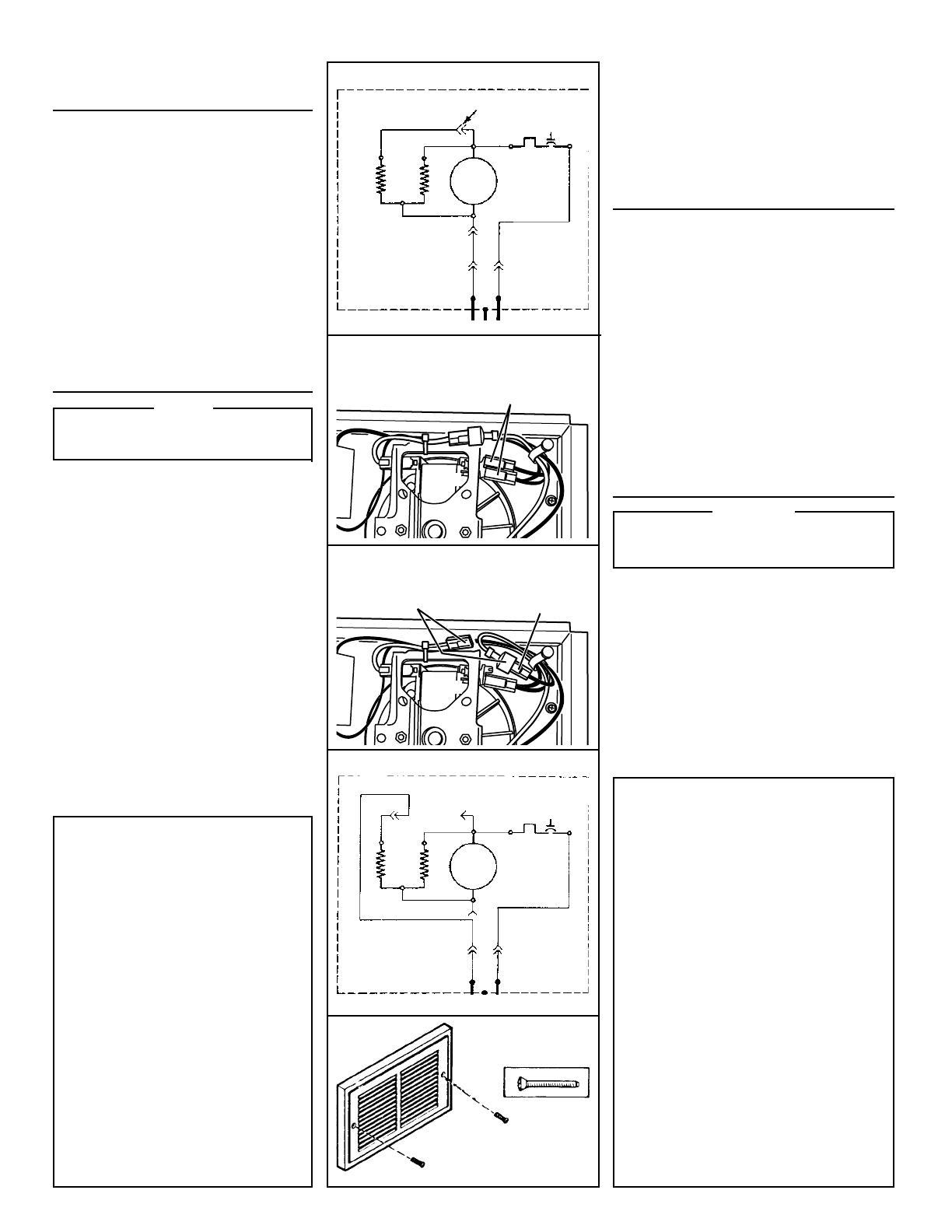
3. Secure heater assembly with retaining screw and
plug wiring harness into receptacle.
4. Fasten grille to heater with two (2) screws pro-
vided. (FIG. 13)
5. Turn on power at service entrance. Turn thermo-
stat to its highest setting and make sure heating
element and blower come on. Then turn it to its
lowest setting and make sure element and blower
shut off.
USE AND CARE
WARNING
DISCONNECT ELECTRIC POWER AT SERVICE
ENTRANCE BEFORE CLEANING OR SERVICING
UNIT.
THERMAL OVERLOAD PROTECTOR
If heater fails to operate when thermostat is turned to
its highest setting: Turn power off at service entrance.
Remove grille and press button marked "RESET".
CLEANING
Clean the heater assembly using the round brush tool
on your vacuum cleaner. Remove large accumulations
of dust, lint, etc., that might impede the flow of air
through the heater. Such blockage will lower its effi-
ciency and create a possible overheating condition.
To clean grille, use a soft cloth which has been moist-
ened with household window cleaner.
CAUTION: METAL AND ELECTRICAL PARTS SHOULD
NEVER BE IMMERSED IN WATER.
BROAN ONE YEAR LIMITED WARRANTY
Broan warrants to the original consumer purchaser of its prod-
ucts that such products will be free from defects in materials or
workmanship for a period of one year from the date of original
purchase. THERE ARE NO OTHER WARRANTIES, EXPRESS
OR IMPLIED, INCLUDING, BUT NOT LIMITED TO, IMPLIED
WARRANTIES OF MERCHANTABILITY OR FITNESS FOR A
PARTICULAR PURPOSE.
During this one-year period, Broan will, at its option, repair or
replace, without charge, any product or part which is found to be
defective under normal use and service.
THIS WARRANTY DOES NOT EXTEND TO FLUORESCENT
LAMP STARTERS AND TUBES. This warranty does not cover (a)
normal maintenance and service or (b) any products or parts
which have been subject to misuse, negligence, accident, im-
proper maintenance or repair (other than by Broan), faulty instal-
lation or installation contrary to recommended installation in-
structions.
The duration of an implied warranty is limited to the one-year
period as specified for the express warranty. Some states do not
allow limitation on how long an implied warranty lasts, so the
above limitation may not apply to you.
BROAN’S OBLIGATION TO REPAIR OR REPLACE, AT BROAN’S
OPTION, SHALL BE THE PURCHASER’S SOLE AND EXCLU-
SIVE REMEDY UNDER THIS WARRANTY. BROAN SHALL NOT
BE LIABLE FOR INCIDENTAL, CONSEQUENTIAL OR SPECIAL
DAMAGES ARISING OUT OF OR IN CONNECTION WITH PROD-
UCT USE OR PERFORMANCE. Some states do not allow the
exclusion or limitation of incidental or consequential damages,
so the above limitation may not apply to you.
This warranty gives you specific legal rights, and you may also
have other rights, which vary from state to state. This warranty
supersedes all prior warranties.
To qualify for warranty service, you must (a) notify Broan at the
address or telephone number below, (b) give the model number
and part identification and (c) describe the nature of any defect
in the product or part. At the time of requesting warranty service,
you must present evidence of the original purchase date.
Broan-NuTone LLC, 926 West State Street, Hartford, WI 53027
(1-800-637-1453)
FIG. 9
BLACK
NEGRO
BLACK
NEGRO
BLACK
NEGRO
BLACK
NEGRO
BLACK
NEGRO
WHITE
BLANCO
WHITE
BLANCO
WHITE
BLANCO
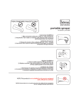
THERMAL
OVERLOAD
SOBRECARGA
TERMICA
HEATING
ELEMENT
ELEMENTO
DE CALOR
M
FIG. 10 - HALF-WATTAGE CONVERSION
CONVERSIÓN DE MEDIO VATIAJE
FIG. 11 - 120VAC TO 240VAC CONVERSION
CONVERSIÓN DE 120VCA A 240VCA
FIG. 12
FIG. 13
THERMAL
OVERLOAD
SOBRECARGA
TERMICA
BLACK
NEGRO
BLACK
NEGRO
M
WHITE
BLANCO
CONVERTED 240 VAC HEATER
CALENTADOR CONVERTIDO
240 VCA
BLACK
NEGRO
WHITE
BLANCO
WHITE
BLANCO
WHITE
BLANCO
WHITE
BLANCO
BLACK
NEGRO
BLACK
NEGRO
DISCONNECT FOR HALF-
WATTAGE
DESCONECTE PARA MEDIO
VATIAJE
BLACK
NEGRO
FACTORY-WIRED
HEATER
(FULL WATTAGE)
CALENTADOR
CABLEADO DE
FABRICA (VATIAJE
COMPLETO)
LINE IN LINEA DE ENTRADA
HEATING
ELEMENT
ELEMENTO
DE CALOR
BLACK
NEGRO
LINE IN LINEA DE ENTRADA 240VCA
(2) BLACK WIRES (connected to motor)
(2) CABLES NEGROS (conectados al motor)
BLACK WIRE (from motor)
CABLE NEGRO (del motor)
WHITE WIRES
CABLES BLANCOS
MOTOR
MOTOR
1) Desconecte del motor UNO de los dos (2) cables negros
(que tienen terminal aislada).
2) Desconecte los dos (2) cables blancos (con terminales
aisladas). No saque el cable blanco debajo del enlace de
cable plástico.
3) Conecte el cable negro al cable blanco.
NOTA: cuando el calentador se convierte de 120 VCA a
240 VCA, no es posible convertir a medio vatiaje.
COMPLETANDO LA
INSTALACION
(CONSTRUCCIONES NUEVAS)
1. Una cubierta de caja se incluye para evitar que el polvo
de construcción, rocíos de yeso, pintura, etc. dañen el
calentador.
Doble las aletas en la cubierta y empújela dentro de la
caja del calentador.
NOTA: la cubierta se puede poner en su lugar antes o
después de reinstalar el conjunto del ventilador.
2. Quite la cubierta antes de la operación.
(TODAS LAS INSTALACIONES)
3. Fije el conjunto del calentador con el tornillo de retención
y enchufe el conjunto de cables preconfigurado al
enchufe.
4. Fije la rejilla al calentador con dos (2) tornillos que se
incluyen.
5. Conecte la potencia en la entrada de servicio. Ponga el
termostato en su graduación más alta y compruebe que
el elemento de calor y el soplador se enciendan. Póngalo
después en su graduación más baja y compruebe que el
elemento y el soplador se apaguen.
USO Y MANTENIMIENTO
ADVERTENCIA
DESCONECTE LA POTENCIA EN LA ENTRADA DE
SERVICIO Y ASEGURE EL PANEL ANTES DE HACER
LA LIMPIEZA O DAR SERVICIO A LA UNIDAD.
PROTECTOR DE SOBRECARGA TERMICA
Si el calentador no funciona cuando el termostato está
prendido en su graduación más alta: apague la energía en
la entrada de servicio. Quite la rejilla y oprima el botón
marcado “RESET”.
LIMPIEZA
Limpie el conjunto de calentador usando el cepillo redondo
de su aspiradora. Saque las acumulaciones grandes de
polvo, pelusa, etc., que puedan impedir el flujo de aire por
el calentador. Ese bloqueo disminuirá la eficiencia y creará
una posible condición de sobrecalentamiento.
Para limpiar la rejilla, use un trapo suave humedecido con
limpiador de ventanas casero.
CUIDADO: LAS PIEZAS METALICAS Y ELECTRICAS
NUNCA SE DEBEN SUMERGIR EN AGUA.