NuTone 9427P Installation guide

Category
Space heaters
Type
Installation guide

This manual is also suitable for

1
INSTALLATION INSTRUCTIONS
READ & SAVE THESE INSTRUCTIONS!
Bulb Heaters & Bulb Heater/Fans
MODELS: 9412D (Not Type IC), 9417DN (Type IC), 9422P (Type IC), 9427P (Type IC)
IMPORTANT INSTRUCTIONS
READ ALL INSTRUCTIONS BEFORE INSTALL-
ING OR USING THIS HEATER.
To reduce the risk of fire, electric shock, or injury to persons, observe
the following:
1. Use this unit only in the manner intended by the manufacturer. If
you have questions, contact the manufacturer at the address or
telephone number listed in the warranty.
2. Before servicing or cleaning unit, switch power off at service panel
and lock the service disconnecting means to prevent power from
being switched on accidentally. When the service disconnecting
means cannot be locked, securely fasten a prominent warning
device, such as a tag, to the service panel.
3. Installation work and electrical wiring must be done by a qualified
person(s) in accordance with all applicable codes and standards,
including fire-rated construction codes and standards.
4. When cutting or drilling into wall or ceiling, do not damage electri-
cal wiring and other hidden utilities.
5. This heater is hot when in use. To avoid burns, do not let bare
skin touch hot surfaces. Keep combustible materials, such as fur-
niture, pillows, bedding, papers, clothes, etc. and curtains at least
3 feet (0.9 m) from the front of the heater.
6. Extreme caution is necessary when any heater is used by or near
children or invalids and whenever the heater is left operating and
unattended.
7. Do not operate any heater after it malfunctions. Disconnect power
at service panel and have heater inspected by a reputable electri-
cian before reusing.
8. Do not use outdoors.
9. To disconnect heater, turn controls to off, and turn off power to
heater circuit at main disconnect panel (or operate internal dis-
connect switch, if provided).
10. Do not insert or allow foreign objects to enter any ventilation or
exhaust opening, as this may cause an electric shock or fire, or
damage the heater.
11. To prevent a possible fire, do not block air intakes or exhaust in
any manner.
12. A heater has hot and arcing or sparking parts inside. Do not use it
in areas where gasoline, paint, or flammable vapors or liquids are
used or stored.
13. Use this heater only as described in this manual. Any other use
not recommended by the manufacturer may cause fire, electric
shock, or injury to persons.
14. This product must be grounded.
15. Do not install heater in a tub or shower enclosure.
16. This product is designed for installation in flat ceilings only. DO
NOT MOUNT THIS PRODUCT IN A WALL.
17. Install heater in flat ceiling only - at least 6 inches from any wall.
18. Do not connect heater to dimmer switch or speed control.
SAVE THESE INSTRUCTIONS
PLANNING
Choose the location for your heater. Refer to IMPORTANT IN-
STRUCTIONS.
MODELS 9417DN & 9427P ONLY – The unit will operate most
efficiently when located where the shortest possible duct run and
minimum number of elbows will be needed. Units are designed
for use with standard 4” round duct.
Note that two-bulb units (9422P & 9427P) can be fitted with one
infrared bulb (for heat) and one reflector bulb (for light). Dual or
multi-controls can be used for separate control of bulbs and/or
exhaust fan. Purchase controls separately.
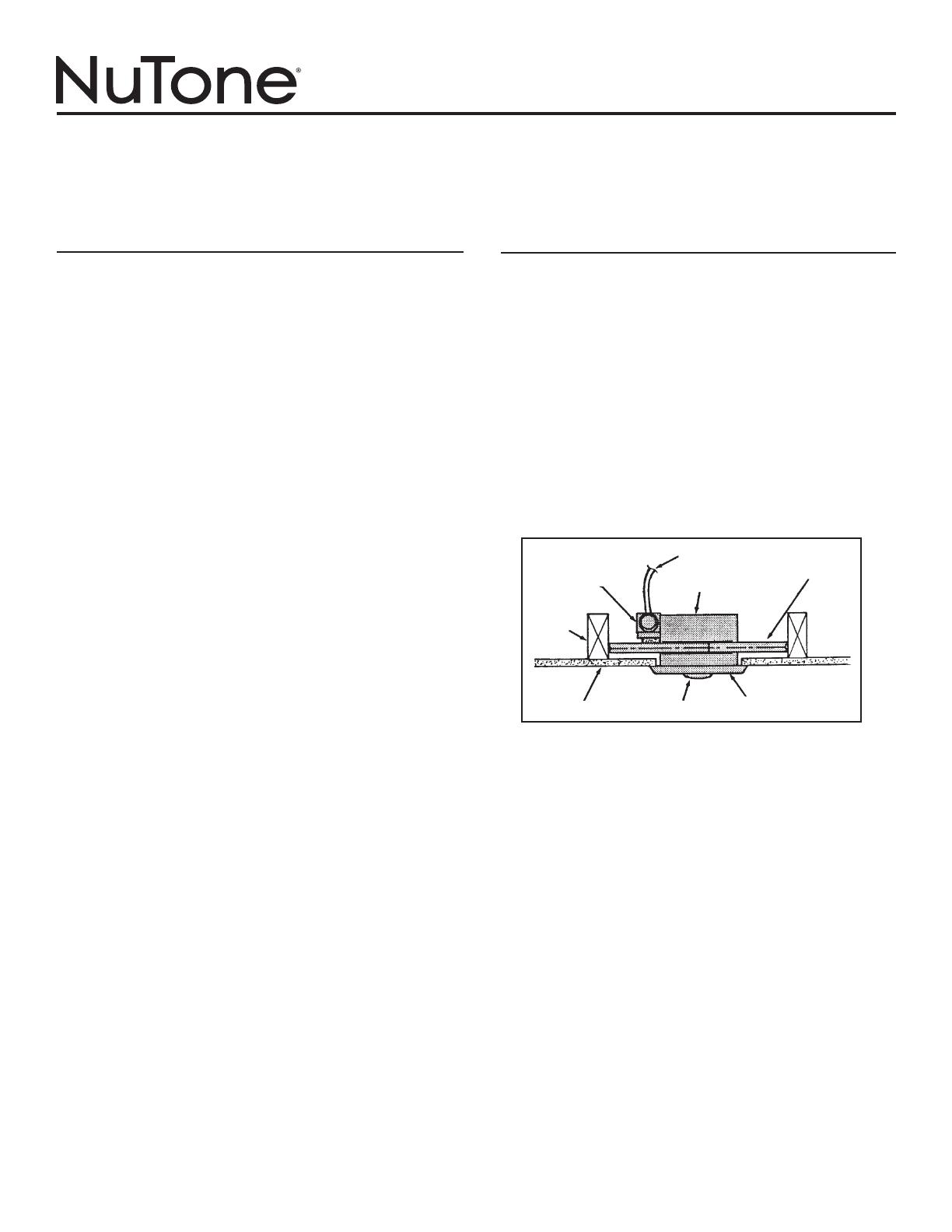
Refer to FIGURE 1
Follow these basic steps when installing this unit:
1. Nail unit to joists.
2. Attach ductwork (Models 9417DN or 9427P only).
3. Connect power cable.
4. Fasten grille to housing.
FIGURE 1
DAMPER/DUCT
CONNECTOR
POWER CABLE
HOUSING
CEILING
JOIST
CEILING MATERIAL BULB(S)
GRILLE
MOUNTING
BRACKET
2
PREPARATION
1. Remove the unit from carton. Save carton for use as plaster
shield in rough-in installations.
Refer to FIGURE 2
2. Slide adjustable mounting brackets into bracket channels on
housing.
FIGURE 2
3
DAMPER/DUCT
CONNECTOR
FIGURE 3
FIGURE 4
VERTICAL ADJUSTING
SCREWS
INSTALLATION
WARNING: To reduce the risk of fire, do not store or use
gasoline or other flammable vapors and liquids in the vicinity
of the heater.
CAUTION: High temperature, risk of fire, keep electrical cords,
drapery, furnishings, and other combustibles at least 3 feet (0.9
m) from the front of the heater and away from the side and rear.
Refer to FIGURE 3
1. Position unit between joists and extend mounting brackets.
2. Nail brackets firmly to joists. Bottom of brackets should be po-
sitioned flush with joist bottom.
Refer to FIGURE 4
3. Brackets are factory-set for ½” thick ceiling material. For thicker
ceilings, loosen 4 vertical adjusting screws and lower housing
to appropriate thickness on gauges. Tighten vertical adjusting
screws firmly.
ATTACH DUCTWORK
(MODELS 9417DN & 9427P ONLY)
Refer to FIGURE 4
1. Snap the damper/duct connector onto housing. Make sure that
tabs on the connector lock in housing slots and that gravity
closes damper.
2. Attach 4” round duct to damper/duct connector and run ductwork
to the outside through a roof or wall cap. Check damper to make
sure it opens freely. Tape all joints to make them secure and air
tight.
4
WIRE THE HEATER
Refer to FIGURE 5
1. Remove wiring box from side of housing. Remove knockout(s)
and connect power cable(s) to wiring box using proper U.L. ap-
proved connector.
Refer to FIGURE 6 (on page 3)
2. Wire unit as indicated in appropriate diagram. Push all wiring
into wiring box and replace wiring box onto housing.
FINAL ASSEMBLY
Refer to FIGURE 7
1. Protect motor, bulb sockets and wiring from construction dust,
drywall spray, paint, etc. by using the plaster shield. Cut it from
the carton and follow directions printed on it.
2. Finish all ceiling work as necessary.
3. Remove plaster shield and check if bottom of housing is flush
with finished ceiling. If not, loosen vertical adjusting screws,
reposition housing, and retighten screws.
Refer to FIGURE 8
4. Attach grille by hooking springs onto clips on side of housing.
5. Install BR40 or R40-size 250W infrared bulb(s). Center grille
around bulb(s).
WIRING BOX
4” ROUND
DUCT
FIGURE 5
FIGURE 8
FIGURE 7
5
OPERATION
Before using heater, make sure heater has been properly installed
according to installation steps beginning with the "PLANNING"
section on page 1.
MODELS 9417DN & 9427P OPERATION NOTE: These units are
designed with a thermostat which senses excess heat and may start
the blower automatically. This is normal and is no cause for concern.
MAINTENANCE
The following maintenance and cleaning tasks can be performed
by the user. All other servicing must be performed by an authorized
technician If you have any questions, please consult with our cus-
tomer service department at: 800-558-1711.
LUBRICATION
The heater is permanently lubricated and never needs oiling or
disassembly.
CLEANING
Clean heater once a month as follows:
1. Turn off power at service panel.
2. Make sure bulbs are cool.
3. Use a soft brush attachment to gently vacuum grille openings or
wipe grille clean with a soft cloth.
4. Restore power.
CAUTION: METAL AND ELECTRICAL PARTS SHOULD NEVER
BE IMMERSED IN WATER.
7
FIGURE 6
MODEL 9412D MODEL 9417DN
Lamp & Vent operate together
MODEL 9417DN
Lamp & Vent operate separately
MODEL 9422P
Lamps operate together
MODEL 9422P
Lamps operate separately
MODEL 9427P
Vent & Heat operate together –
Light separately
MODEL 9427P
Light, Vent & Heat operate separately
MODEL 9427P
Light & Vent operate together –
Heat separately
MODEL 9427P
Lamps operate together –
Vent separately
120 VAC LINE IN
GROUND
BLACK
BLACK
WHITE to
WHITE
WHITE to WHITE
GROUND
BLACK to
BLACK
SWITCH OR TIMER
WHITE to
WHITE / GRAY
120 VAC LINE IN
GROUND
BLACK
BLACK
WHITE
to WHITE
BLACK to
RED & BLUE
GROUND
SWITCH OR TIMER
RED
VENT
WHITE to
WHITE / GRAY
120 VAC LINE IN
BLACK
BLACK
WHITE to
WHITE
BLACK TO BLUE
RED TO RED
GROUND
HEAT
DUAL CONTROL
GROUND
WHITE to
WHITE / GRAY
120 VAC LINE IN
GROUND
BLACK
BLACK
WHITE to
WHITE
BLACK to
BLACK
& RED
GROUND
SWITCH OR TIMER
WHITE to
WHITE / GRAY
120 VAC LINE IN
GROUND
BLACK
BLACK
LIGHT
BLACK to BLACK
GROUND
HEAT
RED
DUAL CONTROL
RED to RED
WHITE to
WHITE
120 VAC LINE IN
GROUND
LIGHT
DUAL CONTROL
3 WHITE / GRAY WIRES
VENT & HEAT
BLACK to BLACK,
& YELLOW
RED to RED
& BLUE
GROUND
RED
WHITE to
WHITE
BLACK
120 VAC LINE IN
GROUND
LIGHT
& VENT
DUAL CONTROL
3 WHITE / GRAY WIRES
HEAT
BLACK to
BLACK, & BLUE
RED to RED
& YELLOW
GROUND
RED
WHITE to
WHITE
BLACK
120 VAC LINE IN
GROUND
VENT
DUAL CONTROL
3 WHITE / GRAY WIRES
HEAT & LIGHT
BLACK to
BLUE
RED to RED,
BLACK &
YELLOW
GROUND
RED
WHITE to
WHITE
BLACK
HEAT
120 VAC LINE IN
GROUND
3 BLACK WIRES
3 WHITE 
WIRES
LIGHT
BLACK
3-FUNCTION CONTROL
WHITE to WHITE / GRAY
VENT
BLACK to BLACK
BLACK to YELLOW
RED to RED
RED
GROUND
WHITE to WHITE
RED to BLUE
8
99045029A
25
25
17
17
3
9412D-R01 9417DN-R01 9422P-R01 9427P-R01
REF. PART NO. PART NO. PART NO. PART NO. DESCRIPTION
1 97010319 97010319 97010320 97010320 Grille Assembly (Includes Ref. No. 2)
2 06170-00 06170-00 06170-00 06170-00 Grille Spring (2 Req.)
3 - - - - 97010254 97009724 97010254 Motor
4 - - - - 98007352 98007426 98007352 Motor Mounting Bracket
5 99770034 99770034 99770034 99770034 Bulb Holder
6 - - - - - - - - 99770037 99770037 Bulb Holder
7 - - - - 99260423 99260423 99260423 Nut, #8-32 (2 Req.)*
8 - - - - 99160360 99160360 99160360 Screw, #8-32 x 1/2 (2 Req.)*
9 99150545 99150545 99150545 99150545 Sheet Metal Screw #8-18 x 3/8 (5 Req.) (7 Req. – 9412D-R01)*
10 99150546 99150546 99150546 99150546 Ground Screw #8-18 x 3/8
11 - - - - 97010255 - - - - 97010255 Blower Wheel
12 - - - - - - - - 97009762 - - - - Fan Blade
13 97009475 97009476 97009477 97009478 Housing (Includes Ref. Nos. 9 & 23)
14 - - - - 97009595 - - - - 97009595 Damper/Duct Connector
15 25067-00 20050-09 20050-09 20050-09 Wiring Box Cover
16 99400026 99400026 99400026 99400026 Bushing (2 Req. – 9422P-R01 & 9427P-R01)
17 99270830 99270830 99270830 99270830 Wire Clip
19 - - - - 99270835 99270835 99270835 Receptacle
20 - - - - 99270832 - - - - 99270832 Thermostat (Fan)
21 98003036 98003036 98003036 98003036 Mounting Bracket (4 Req.)
22 98007763 98007763 98007763 98007763 Bracket Channel (2 Req.)
23 25064-00 25064-00 25064-00 25064-00 Wiring Box
24 99150564 99150564 99150564 99150564 Screw, #8-18 x ½*
25 - - - - 79270237 79270237 79270237 Thermostat (Lamps)
** - - - - - - - - 99270668 99270668 Crimp Connector (2 Req. – 9422P-R01) (3 Req. – 9427P-R01)
PARTS LIST
BROAN-NUTONE ONE YEAR LIMITED WARRANTY
Broan-NuTone warrants to the original consumer purchaser of its products that such products will be free from defects in materials or workmanship for a period of one year from the date of original
purchase. THERE ARE NO OTHER WARRANTIES, EXPRESS OR IMPLIED, INCLUDING, BUT NOT LIMITED TO, IMPLIED WARRANTIES OF MERCHANTABILITY OR FITNESS FOR A PARTICULAR
PURPOSE.
During this one-year period, Broan-NuTone will, at its option, repair or replace, without charge, any product or part which is found to be defective under normal use and service.
THIS WARRANTY DOES NOT EXTEND TO FLUORESCENT LAMP STARTERS, TUBES, HALOGEN AND INCANDESCENT BULBS, FUSES, FILTERS, DUCTS, ROOF CAPS, WALL CAPS AND OTHER ACCES-
SORIES FOR DUCTING. This warranty does not cover (a) normal maintenance and service or (b) any products or parts which have been subject to misuse, negligence, accident, improper maintenance
or repair (other than by Broan-NuTone), faulty installation or installation contrary to recommended installation instructions.
The duration of any implied warranty is limited to the one-year period as specified for the express warranty. Some states do not allow limitation on how long an implied warranty lasts, so the above
limitation may not apply to you.
BROAN-NUTONE’S OBLIGATION TO REPAIR OR REPLACE, AT BROAN-NUTONE’S OPTION, SHALL BE THE PURCHASER’S SOLE AND EXCLUSIVE REMEDY UNDER THIS WARRANTY. BROAN-
NUTONE SHALL NOT BE LIABLE FOR INCIDENTAL, CONSEQUENTIAL OR SPECIAL DAMAGES ARISING OUT OF OR IN CONNECTION WITH PRODUCT USE OR PERFORMANCE. Some states do not
allow the exclusion or limitation of incidental or consequential damages, so the above limitation or exclusion may not apply to you.
This warranty gives you specific legal rights, and you may also have other rights, which vary from state to state. This warranty supersedes all prior warranties.
To qualify for warranty service, you must (a) notify Broan-NuTone at the address or telephone number below, (b) give the model number and part identification and (c) describe the nature of any defect
in the product or part. At the time of requesting warranty service, you must present evidence of the original purchase date.
Broan-NuTone LLC, 926 W. State Street, Hartford, Wisconsin 53027 www.nutone.com 888-336-3948
WARRANTY
MODELS 9412D-R01 & 9417DN-R01 MODELS 9422P-R01 & 9427P-R01
MODEL 9422P-R01 ONLY
  • Page 1 1
  • Page 2 2
  • Page 3 3
  • Page 4 4
  • Page 5 5
  • Page 6 6
  • Page 7 7
  • Page 8 8
  • Page 9 9
  • Page 10 10
  • Page 11 11
  • Page 12 12
  • Page 13 13
  • Page 14 14
  • Page 15 15
  • Page 16 16

NuTone 9427P Installation guide

Category
Space heaters
Type
Installation guide
This manual is also suitable for

Ask a question and I''ll find the answer in the document

Finding information in a document is now easier with AI

in other languages