Page is loading ...

®
Galleria 30 and 36
Range Hood
User Manual
&
Installation Instructions
IMPORTANT SAFETY INSTRUCTIONS
Carefully read the important information
regarding installation, safety and maintenance.
Keep these instructions for future reference.
MAAN1198-05
2018-05-25

— 2 —
INSTALLERS - Start Here
Safety Instructions are on pages 4 and 5 and
Installation Instructions are on pages 9 to 15.
Please perform these steps:
1. Read the safety instructions.
2. Read all instructions in the Installation section of
this manual BEFORE installing the range hood.
3. Remove all packing materials.
4. When nished, make sure to leave these instructions with the consumer.
5. Installation is to be done by a qualied technician only. However, the
ultimate responsibility for proper installation falls to the owner.
6.
Product failure due to improper installation is not covered under the Warranty.
CONSUMERS - Start Here
Safety Instructions are on pages 4 and 5 and Operating Instructions are
on pages 16, 17 and 21.
Please perform these steps:
1. Read the safety instructions.
2. Read all instructions in the manual BEFORE operating the range hood.
3. Remove all packing materials.
4. Installation is to be done by a qualied technician only. However, the
ultimate responsibility for proper installation falls to the owner.
5.
Product failure due to improper installation is not covered under the Warranty.
Before You Begin
Hardware Note: For safety reasons, range hood mounting screws and anchors will not be
included due to the variation of cabinetry constructions and wall material. Please consult your
installation specialist regarding the optimal type of mounting screws and wall anchors to suit your
home’s construction.

— 3 —
Before You Begin ............................................................................................................................... 2
Table of Contents .............................................................................................................................. 3
Important Safety Information ............................................................................................................ 4
Included Parts ................................................................................................................................... 6
Range Hood Dimensions .................................................................................................................. 7
Specications .................................................................................................................................... 7
Mounting Brackets ............................................................................................................................ 8
Installation ......................................................................................................................................... 9
Step 1 - Read the Safety Instructions ............................................................................................ 9
Step 2 - Unpack Range Hood and Prepare Tools .......................................................................... 9
Step 3 - Plan Desired Location ...................................................................................................... 9
Step 4 - Test Unit Functions .......................................................................................................... 9
Step 5 - Venting Installation Guidelines ....................................................................................... 10
Step 6 - Preparations ................................................................................................................... 12
Step 7 - Installing the Hood Mounting Bracket and Hood ........................................................... 12
Step 8 - Connect Ductwork ......................................................................................................... 13
Step 9 - Connect to AC................................................................................................................ 13
Step 10 - Install Chimney ............................................................................................................. 14
Step 11 - Install Filters ................................................................................................................. 15
Operation ........................................................................................................................................ 16
Power Settings ............................................................................................................................. 16
Lights ........................................................................................................................................... 16
Troubleshooting............................................................................................................................... 16
Maintenance.................................................................................................................................... 17
Replacing the Light Pucks ........................................................................................................... 17
Cleaning Filters ............................................................................................................................ 17
Range Hood Assembly ................................................................................................................... 18
Assembly ......................................................................................................................................... 20
Circuit Diagram ............................................................................................................................ 20
Blower Assembly ......................................................................................................................... 20
Electrical Assembly ...................................................................................................................... 20
Use and Care Information ............................................................................................................... 21
Table of Contents

— 4 —
Important Safety Information
• Theinstallationinthismanualisintended
for qualied installers, service technicians or
persons with a similar qualied background.
Installation must be done by qualied
professionals and in accordance with all
applicable codes and standards, including
re-rated construction.
•
The range hood may have very sharp
edges; please wear protective gloves if it is
necessary to remove any parts for installing,
cleaning or servicing.
•
Activating any switch to ON position before
completing installation may cause damage or
electric shock.
• Duetothesizeofthisrangehood,atwo-
person installation is recommended.
To reduce the risk of re, electric shock, or
injury to persons:
• Forgeneralventilatinguseonly.DO NOT use
toexhausthazardousorexplosivematerials
and vapors.
• WARNING: To Reduce The Risk Of Fire Or
Electric Shock, Do Not Use This Fan With Any
Solid-State Speed Control Device.
• Thecombustionairowneededforsafe
operation of fuel-burning equipment may be
affected by this unit’s operation. Follow the
heating equipment manufacturer’s guideline
and safety standards such as those published
by the National Fire Protection Association
(NFPA), and the American Society of Heating,
Refrigeration and Air Conditioning Engineers
(ASHRAE), and other local code authorities.
• Beforeservicingorcleaningtheunit,switch
power off at service panel and lock the service
disconnecting means to prevent power from
being switched on accidentally. When the
service disconnecting means cannot be
locked, securely fasten a prominent warning
device, such as a tag, to the service panel.
• Cleangrease-ladensurfacesfrequently.To
optimizeperformanceandtodisperseair
properly, make sure to vent air outside. DO
NOT vent exhaust into spaces between walls,
crawl spaces, ceilings, attics or garages.
•
Ducted fans MUST always be vented to
the outdoors.
• ThisunitMUSTbegroundedandusedwith
metal ductwork only.
• Sufcientairisneededforpropercombustion
and exhausting of gases through the duct to
prevent back drafting.
• Whencuttingordrillingintowallorceiling,be
careful not to damage electrical wiring or other
hidden utilities.
• Allelectricalwiringmustbeproperlyinstalled,
insulated and grounded.
•
Old ductwork should be cleaned or replaced
if necessary to avoid the possibility of a
grease re.
•
Check all joints on ductwork to ensure
proper connection; all joints should be
properly taped using a certied aluminum
or foil tape.
• Usethisunitonlyinthemannerintended
by the manufacturer. If you have questions,
contact the vendor.
READ AND SAVE THESE
INSTRUCTIONS
READ ALL INSTRUCTIONS BEFORE USE
Read and follow all instructions before using the range hood to prevent the risk of re, electric shock,
personal injury, or damage when using the range hood or appliances with the range hood. This guide
does not cover all possible conditions that may occur. Always contact your service technician or
manufacturer about problems that you do not understand.

— 5 —
Important Safety Information
WARNING: TO REDUCE RISK OF A RANGE
TOP GREASE FIRE:
a) Never leave surface units unattended at high
settings. Boilovers cause smoking and greasy
spillovers that may ignite. Heat oils slowly on
low or medium settings.
b) Always turn range hood ON when cooking at
highheatorwhenambéingfood(i.e.Crepes
Suzette,CherriesJubilee,etc.).
c)
Clean ventilating fans frequently. Grease should
not be allowed to accumulate on fan or lter.
Before servicing or cleaning unit, unplug and
disconnect the hood from the power supply.
d)Useproperpansize.Alwaysusecookware
appropriateforthesizeofthesurfaceelement.
WARNING: TO REDUCE RISK OF INJURY TO
PERSONS IN THE EVENT OF A RANGE TOP
GREASE FIRE, OBSERVE THE FOLLOWING *
a) S
MOTHER FLAMES with a close-tting
lid, cookie sheet, or metal tray, then turn
off the burner. BE CAREFUL TO PREVENT
BURNS.Iftheamesdonotgoout
immediately, EVACUATE AND CALL THE
FIRE DEPARTMENT.
b) NEVER PICK UP A FLAMING PAN - You may
be burned.
c) DO NOT USE WATER, including wet dishcloths
or towels - a violent steam explosion will result.
d) Use an extinguisher ONLY if:
1) You know you have a Class A, B, C
extinguisher, and you already know how to
operate it.
2) The re is small and contained in the area
where it is started.
3) The re department is being called.
4)
You can ght the re with your back to an exit.
* Based on “Kitchen Fire Safety Tips”
published by NFPA
To reduce the risk of injury to persons in the
event of a gas leaks:
• Extinguishanyopename.
•
DO NOT turn on the lights or any type of appliance.
• Openalldoorsandwindowstodispersethe
gas. If you still smell gas, call the gas company
and re department.
Your safety and the safety of others is very
important. We have provided many important
safety messages in this manual and on your
appliance. Always read and obey all safety
messages. All safety messages outline any
potentialhazards,howtoreducethechanceof
injury, and possible risks if the instructions are not
followed.
READ AND SAVE THESE
INSTRUCTIONS

— 6 —
Included Parts
Main Housing
2Bafelters
Upper Chimney
Lower Chimney
Upper Chimney Bracket
Hardware Note: For safety reasons, range hood mounting screws and anchors will not be included due to
the variation of cabinetry constructions and wall material. Please consult your installation specialist regarding
the optimal type of mounting screws and wall anchors to suit your home’s construction.
4 + 1 Handle screws
Hood Mounting Bracket
Grease tunnel
6 + 1 Screws A 6 + 1 Screws B
Bafelterspacer
4 Handles

— 7 —
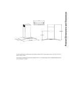
Range Hood Dimensions
Specications
Body Design Stainless Steel
Power Rating 120V/60Hz(cETLusCertied)
Total Input Power 314 W (308 W + 2 x 3 W)
Motor Input Power 308 W
Amperage 2.6 A
Speed Control Levels 4 Speeds
Interference Protection Radio Frequency Interference Protected
Motors Single Motor
Control Electronic button control panel
Filtration Bafelter
Illumination 2 x 3 W LED lights
Fan Type Single chamber quiet
VentingSize Top, 6 inches (15.3 cm) round
Galleria 30 in. and 36 in.
30 in. (75.6 cm) / 36 in. (90.8 cm)
20.5 in. (52.2 cm)
12.2 in.
(31.1 cm)
15.7 in. -
31.5 in.
(40 cm -
80 cm)
7.8 in. (20 cm)
10.6 in. (27 cm)
8.6 in. (22 cm)
10.45 in. (26.55 cm)
2.04 in.
(5.2 cm)
8.9 in. (22.8 cm)
1.9 in. (5 cm)
12.2 in.
(31.1 cm)
30 in. (75.6 cm) /
36 in. (90.8 cm)
20.5 in. (52.2 cm)
7.8 in. (20 cm)
10.6 in. (27 cm)
5.2 in.
(13.4 cm)
4.2 in.
(10.9 cm)
1 in. (2.5 cm)
Ø 5.8 in. (14.8 cm)
2.04 in.
(5.2 cm)

— 8 —
Mounting Brackets
Hood-mounting Bracket
0.2 in. (0.6 cm)
0.7 in. (1.8 cm)
0.31 in. (0.8 cm)
Ø 0.2 in. (0.6 cm)
0.39 in. (1 cm)
2.2 in.
(5.6 cm)
1.3 in.
(3.5 cm)
0.39 in. (1 cm)
4.7 in.
(12 cm)
8.9 in. (22.8 cm)
10.2 in. (26 cm)
1.18 in. (3 cm)
1 in.
(2.5 cm)
10.4 in. (26.5 cm)
8.6 in. (22 cm)
0.6 in. (1.7 cm)
Chimney-mounting Bracket

— 9 —
STEP 1
Read the Safety Instructions
• It is very important to read the safety instructions on pages 4 and 5.
IMPORTANT: It is the installer’s responsibility to comply with installation clearances.
STEP 2
Unpack Range Hood and Prepare Tools
• Carefully unpack the range hood and parts. Make sure all parts are included as shown on page 6.
• DO NOT remove the protective lm covering the appliance until the installation is fully completed.
• Consult a qualied and trained installer or check local codes for makeup air requirement, if any.
STEP 3
Plan Desired Location
• Plan a desirable location that ts all requirements in the Safety and Installation sections of this manual. Plan where
and how the ductwork will be installed.
• A straight or short duct run will allow the unit to perform most efciently. Long duct runs, elbows and transitions
will reduce the performance of the unit. Each elbow is equivalent to 5 to 10 feet (1.5 à 3.0 m) of straight run.
Propersizeductworkshouldbe6in.(15.3cm)indiameter.
• To reach a 9 foot ceiling make sure hood is installed 30 inches (
76.2 cm)
from cooking surface. If you have a
ceiling greater than 9 ft, please visit anconahome.com to order a chimney extension.
• If ductwork is already installed: ensure ductwork is free from debris and measures 6 in.
(15.3 cm). (1 in. (2.5 cm)
reducers may be used but more than 1 in. (2.5 cm) will overwork the motor and the unit will not function properly).
STEP 4
Test Unit Functions
• Plug the unit in and test all of the functions before installing.
• Placetherangehoodonaat,stablesurface.Connecttherangehoodtoadesignatedstandardoutlet(120-Volt,60Hz,
AC only) and turn on the range hood. Verify all operations of the range hood by referring to
Range Hood Operations.
• Turn power On in control panel.
• Check all lights and fan operations.
WARNINGS:
• PleasemakesuretoreadALLsafetyinstructionsonpages4and5.
• Usetwoormorepeopletomoveandinstallrangehood.
• Failuretofollowtheseinstructionscanresultinseriousinjury.
Installation

— 10 —
Installation
STEP 5
Venting Installation Guidelines
• The following steps are for exterior ventilation.
Height and Clearance
24 in. (610 mm) Min / 30 in. (762 mm) Max recommended
To reach 9 ft (2.74 m) ceiling, make sure
range hood is installed at least
30 in. (762 mm) from cooking surface.
36 in.
(914 mm)
110 in.
(2794 mm)
IMPORTANT:
•
Vent system must terminate to the outside (roof or side wall).
• DONOT
terminate the vent system in an attic or other
enclosed area.
• DONOTuse4in.(10.2cm)laundry-typewallcaps.
• Usemetal/aluminumventonly.Arigidmetal/aluminum
vent is recommended.
• DONOTuseaplasticvent.
• Alwayskeeptheductcleantoensureproperairflow.
• Calculatethefollowingfiguresbeforeinstallation:
1. Distance from the floor to the ceiling
2. Distance between the floor and the countertop/stove
3.
A distance of 24 in. to 30 in. (61 cm to 76.2 cm) is
recommended between stove top and the bottom of
range hood. 30 in. (76.2 cm) minimum is required for
gas stove tops.
4. Height of hood and duct cover.
For the most efficient and quiet operation:
• Itisrecommendedthattherangehoodbevented
vertically through the roof through 6 in. (15.3 cm) or
bigger round metal/aluminum vent work.
• Thesizeoftheventshouldbeuniform.
• Usenomorethanthree90°elbows.
•
Make sure there is a minimum of 24 in. (61 cm) of
straight vent between the elbows if more than one
elbow is used.
• DONOTinstalltwoelbowstogether.
•
The length of vent system and number of elbows should be
kept to a minimum to provide efficient performance.
• Theventsystemmusthaveadamper.Ifrooforwall
cap has a damper, you may remove damper flaps from
damper to increase air flow.
• Onlyoneflangeisneededintheairductsystem,either
on top of the motor or outside.
•
Use silver tape or duct tape to seal all joints in the
vent system.
•
Use caulking to seal exterior wall or roof opening
around the cap.

— 11 —
Installation
• This range hood is factory set for venting through the roof or wall.
• Ventworkcanterminateeitherthroughtherooforwall.Toventthroughawall,a90°elbowisneeded.
IMPORTANT:
• NEVER exhaust air or terminate duct work into spaces between walls, crawl spaces, ceiling, attics or
garages. All exhaust must be ducted to the outside.
• Use metal/aluminum duct work only.
• Fasten all connections with sheet metal screws and tape all joints with certied Silver Tape or Duct Tape.
• Use caulking to seal exterior wall or roof opening around the cap.
TOP VENTING ROOF EXHAUSTTOP VENTING WALL EXHAUST
Side wall cap
Roof cap
IMPORTANT:
•
A minimum of 6 in. (15.2 cm) round or 3-1/4 x 10 in.
(25.4 cm
x 8.3 cm)
rectangular duct (purchased separately) must be
used to maintain maximum airflow efficiency.
• Alwaysuserigidtypemetal/aluminumductsifavailableto
maximizeairflowwhenconnectingtoprovidedduct.
• PleaseuseDuctRunCalculationbelowtocompute
total available duct run when using elbows, transitions
and caps.
• ALWAYS,whenpossible,reducethenumberor
transitions and turns. If long duct run is required,
increaseductsizefrom6in.(15.2cm)to7in.(17.7
cm) or 8 in. (20.3 cm). If a reducer is used, install a
long reducer instead of a pancake reducer. Reducing
ductsizewillrestrictairflowanddecreaseairflow,thus
reduceductsizeasfarawayfromopeningaspossible.
• Ifturnsortransitionsarerequired,installasfaraway
from opening and as far apart, between two (2), as
possible.
• Minimummountheightbetweenstovetoptohood
bottom should be no less than 24-inch (61 cm) for
electric cook tops and minimum of 30-inch (76.2 cm)
for gas stove tops and no higher than 30-inch (76.2 cm)
for electric cook tops.
• Itisimportanttoinstallthehoodatthepropermounting
height. Hoods mounted too low could result in heat
damageandfirehazard;whilehoodsmountedtoohigh
may be hard to reach and will lose its performance and
efficiency.
• Ifavailable,alsorefertostovetopmanufacturer’s
height clearance requirements and recommended
hood mounting height above range.

— 12 —
Installation
STEP 6
Preparations
NOTE: To avoid damage to your hood, prevent debris from entering the vent opening.
• Determine and mark the center line on the ceiling or wall where the range hood will be installed.
• Make sure there is proper clearance within the ceiling or wall for exhaust vent.
• Duetotheweightandsizeofthisunit,pleasemakesurethatthesupportsystemorframeworkbeingusedisstableand
secure in the ceiling or wall.
• Put a thick, protective covering over counter top, cooktop or range to protect from damage or dirt.
• Removeanyhazardousobjectsaroundtheareawheninstalling.
CAUTION
If moving the cooking range is necessary to install the hood, turn OFF the power on an electric range at the main
electrical box. SHUT OFF THE GAS BEFORE MOVING A GAS RANGE.
STEP 7
Installing the Hood Mounting Bracket and Hood
• Using references in Height & Clearance on Page 10 and Measurements and Diagrams on Page 7, use a pencil to mark
the leveling point of the hood. Position two mounting screws on the wall, leaving 1/8 in. space away from the wall.
• Position the chimney-mounting bracket directly above the hood-mounting bracket, mark the leveling points and secure
it using two mounting screws.
NOTE: Use threaded drywall anchors only when mounting the hood on sheet rock. Mounting the hood on wall studs
or lumbers is highly recommended.
Fig #1
Fig #2
• Attach the hood-mounting bracket to the back of the hood with six screws as shown in Figure 1.
• Align hood-mounting bracket to the screws on the wall and hook hood into place as shown in Figure 2 and Figure 3.
Tighten screws to secure hood to the wall.
• For safety purpose, pre-drilled mounting holes are provided through the back of the hood. For a more secure
installation, use as many mounting holes as needed to secure from the inside of hood.
CAUTION - Make certain the range hood is secure before releasing!
Fig #3

— 13 —
Installation
STEP 8
Connect Ductwork
• Use 6 in. round steel pipe (follow building codes in your area) to connect the
exhaust on the hood to the ductwork above.
• Attach ductwork to damper. Secure the ductwork with duct tape to make
sure joints are secure and air- tight. Refer to Figure 4.
• Donotinstalltheducttapetootightlyasthismaypreventthedamperaps
from opening which will overwork the motor and cause improper functioning
of the unit.
• Fasten all connections with sheet metal screws and tape all joints with
certied aluminum or foil tape. Use caulking to seal exterior wall or roof
opening around the cap.
Fig #4
SAFETY WARNING: Risk of electrical shock. This range hood must be properly grounded. Make sure this
is done by qualied electrician in accordance with all applicable national and local electrical codes. Before
connecting wires, switch power off at service panel and lock service panel to prevent power from being switched
on accidentally.
STEP 9
Connect to AC
• Connect AC plug into a grounded AC outlet having 120 V,
60Hz.Placetheoutletatamaximumdistanceof33-1/2in.
(851 mm) from where the cord exits on the hood.
3-Pronged Plug
Ground Plug
3-Prong Receptacle
IMPORTANT:
• Observeallgoverningcodesandordinances.
• It is the customer’s responsibility to contact a qualified electrical installer.
• Ifcodespermitandaseparategroundwireisused,itisrecommendedthataqualifiedelectriciandeterminethat
thegroundpathisadequate.A120-Volt,60Hz,AC-only,fusedelectricalsupplyisrequiredonaseparate15-amp
circuit, fused on both sides of the line.
• DONOTgroundtoagaspipe.
• Checkwithaqualifiedelectricianifyouarenotsurethattherangehoodisproperlygrounded.
• DONOThaveafuseintheneutralorgroundcircuit.
IMPORTANT: Save this Installation Guide for electrical inspector’s use.
• Or cut off the plug and connect three wires (black, white and green) to house wires and cap with wire connectors.
Connect according to colors (i.e. black to black, white to white, and green to green). Store excess wires in the wiring
box.
• SEE IMPORTANT INSTRUCTIONS BELOW AND ON NEXT PAGE.

— 14 —
Installation
STEP 10
Install Chimney
• Place chimney on top of the main housing.
• Remove the protective coating from the upper chimney. Carefully slide the upper chimney down into the lower chimney.
Make sure upper chimney is moving freely.
• Install both chimneys and tighten screws to secure the lower chimney to the range hood as shown in Figure 5.
• To avoid scratching the chimney, extend the upper chimney slowly and carefully to the chimney-mounting bracket and
tighten screws as shown in Figure 6.
Fig #6
Fig #5
GROUNDING INSTRUCTIONS:
• Thisappliancemustbegrounded.Intheeventofanelectricalshort-circuit,groundingreducestheriskofelectric
shock by providing an escape wire for the electric current.
• Thisapplianceisequippedwithacordhavingagroundingwirewithagroundingplug.Theplugmustbepluggedinto
an outlet that is properly installed and grounded.
WARNING: Improper grounding can result in a risk of electric shock.
• Consultaqualifiedelectricianifthegroundinginstructionsarenotcompletelyunderstood,orifdoubtexistsasto
whether the appliance is properly grounded. DO NOT use an extension cord. If the power supply cord is too short,
have a qualified electrician install an outlet near the appliance.

— 15 —
Installation
STEP 11
Install Filters
Assemble the metal handles to the lters using provided screws, before installing them in range hood.
• Angle and insert one end of the lter into the upper channel of the range hood (Fig #7).
• Raise the other end towards the inside of range hood, rotate and insert in the bottom end of opening (Fig #8 and #9).
• Release the handle once the lter ts into a resting position.
• Repeat to install all lters.
Fig #8Fig #7 Fig #9
Installation Overview

— 16 —
Operation
Power Settings
u
Rotate the knob clockwise to turn the blower ON.
v
To increase the speed continue to rotate the switch
clockwise from speed 1 to speed 4.
w
To decrease the speed rotate the switch
counterclockwise from speed 4 to speed 1.
x
Continue to rotate the switch counterclockwise to turn
the blower OFF.
Lights
u
Rotate the knob clockwise to turn the lights ON, and
rotate the knob counterclockwise to turn light OFF.
Troubleshooting
Problem Possible Cause
If the range hood or LED light
does not operate after installation:
Check if the range hood has been plugged in, make sure that all power
has been turned back ON, fused not blown and all electrical wiring are
properly connected.
Swap out light assembly to working ones to determine whether it is
caused by defective bulbs. See Replacing the light pucks on Page 17.
The range hood vibrates when the
blower is on:
The range hood might not have been secured properly on to the ceiling or
wall.
The blower or fan seems weak: Checkthattheductsizedusedisatleast6in.(15.2cm)or31/4x10in.
(25.4 x 8.3 cm). Range hood WILL NOT function efciently with insufcient
ductsize.Forexample:7in.(17.7cm)ductover6in.(15.2cm)holeand
loosely secured.
Checkifductiscloggedorifdamperunit(half-circularange)isnot
installed correctly or opening properly. A tight mesh on a side wall cap unit
mightalsocauserestrictiontotheairow.
The lights work but the fan is not
spinning at all, is stuck or is rattling:
The fan might be jammed or scraping the bottom due to shipping damage.
Please contact us immediately.
The hood is not venting out
properly:
Make sure the distance between the stove top and the bottom of the hood
is within 24 in. and 30 in. (61 and 76.2 cm) in distance.
Reduce the number of elbows and length of duct work. Check if all joints
are properly connected, sealed, and taped.
OFF
1
2
4
3
OFF
ON
Speed Control
Light Control
OFF
1
2
4
3
OFF
ON

— 17 —
Maintenance
Replacing the Light Pucks
u
Make sure the range hood is unplugged or turn OFF
breaker.
v
Remove lters. Reach into interior of range hood
until touching both lateral clips located on the side
ofthepucklight.Gentlysqueezeandpushdown
until puck pops out from its location, pull out the
LED puck and unplug it.
CAUTION: PUCK MAY BE HOT, PLEASE TAKE
OUT THE PUCK WHEN THE PUCK IS
COMPLETELY COOL!
w
Replace with a 10.2 Volt, 3 Watt max, LED lights.
Plug in new puck and push back into light panel.
x
Turn ON breaker and range hood to test for
operation.
IMPORTANT:
ALWAYS SWITCH OFF THE ELECTRICITY SUPPLY AT THE MAIN PANEL BEFORE CARRYING OUT ANY OPERATION
ON THE APPLIANCE.
Fig #14 Fig #15
Cleaning Filters
IMPORTANT: Drain oil from bafes, spacers, lters, oil tunnels, oil containers before oil and residue overow!
• Removeallbafes,spacers,lters,greasetray,andoilcontainersanddiscardoilandresidue.
• Washwithwarmsoapywater.NOTE:Stainlesssteelbafes,spacersandoiltunnelaretoprackdishwashersafe.
• Dry thoroughly before replacing and follow directions for installation in reverse.
• Filters should be cleaned after every 30 hours of use.
• Should lters wear out due to age and prolonged use, replace with a new lter.

— 18 —
Range Hood Assembly
Number Part
1 Hood Casing
2 Hood-Mounting Bracket
3 Power Cable
4 Top Panel
5 Blower
6 Capacitor
7 LED light
8 Rotary Switch
9 Light Panel
10 Oil Tunnel
11 BafeFilter
12 BafeFilterHandle
13 BafeFilterSpacer
14 Chimney Set
30 inch

— 19 —
Number Part
1 Hood Casing
2 Hood-Mounting Bracket
3 Power Cable
4 Top Panel
5 Blower
6 Capacitor
7 LED light
8 Rotary Switch
9 Light Panel
10 Oil Tunnel
11 BafeFilter
12 BafeFilterHandle
13 BafeFilterSpacer
14 Chimney Set
Range Hood Assembly
36 inch

— 20 —
Assembly
Circuit Diagram
Blower Assembly
Electrical Assembly
Number Part
1 Motor
2 Air Chamber
3 Squirrel Cage
4 Locknut
5 Safety screen
Number Part
1 Screws (3/16 in. x 3/8 in.)
2 Electrical Box Cover
3 Processor Board
4 Screws (3/16 in. x 3/8 in.)
5 Electrical Box Base
6 Electrical Panel
7 Capacitor
8 Screws (3/16 in. x 3/8 in.)
9 LED Light Transformer
/