
Cisco Catalyst 9400 Series Switches Hardware Installation Guide
First Published: 2017-09-20
Last Modified: 2021-06-22
Americas Headquarters
Cisco Systems, Inc.
170 West Tasman Drive
San Jose, CA 95134-1706
USA
http://www.cisco.com
Tel: 408 526-4000
800 553-NETS (6387)
Fax: 408 527-0883

CONTENTS
Safety Warnings 1
CHAPTER 1
Product Overview 5
CHAPTER 2
Switch Models 5
Catalyst 9404R Switch 5
Catalyst 9407R Switch 8
Catalyst 9410R Switch 13
Fan Tray Assembly 17
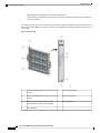
Fan Tray Assembly Overview 17
Operation 19
High Availability 19
Thresholds, Alarms, and Abnormal Acoustic Conditions 19
Power Supply Module 20
Power Supply Module Overview 20
Power Supply Modes 24
Power Supply Module Installation Considerations 25
Preparing for Installation 27
CHAPTER 3
Site Requirements 27
Temperature 28
Air Flow 28
Humidity 30
Altitude 30
Dust and Particles 30
Air Quality 31
Cisco Catalyst 9400 Series Switches Hardware Installation Guide
ii
Contents

Corrosion 31
EMI and Radio Frequency Interference 32
Shock and Vibration 33
Power Source Interruptions 33
System Grounding 34
Maintaining Safety with Electricity 36
Preventing ESD Damage 37
Power Requirements 38
Power Connection Guidelines for AC-Powered Systems 38
Power Connection Guidelines for DC-Powered Systems 39
Cabling Requirements 43
Rack-Mounting Guidelines 43
Site Preparation Checklist 45
Standard Accessory Kit Contents 47
CHAPTER 4
Installing the Switch 49
CHAPTER 5
Installation Tasks 49
Unpacking the Switch 51
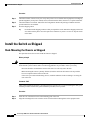
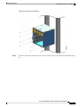
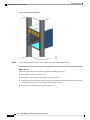
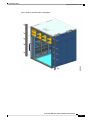
Install the Switch as Shipped 52
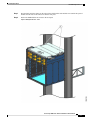
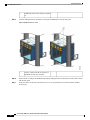
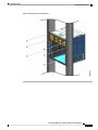
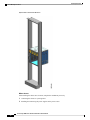
Rack-Mounting the Chassis as Shipped 52
Install the Switch with Shelf Brackets 55
Shelf Kit Contents 55
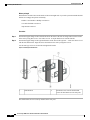
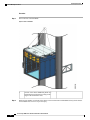
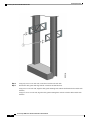
Installing the Shelf Kit L Brackets 56
Installing the Shelf Brackets 59
Rack-Mounting the Chassis 61
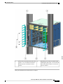
Installing the Cable Guide 67
Installing the Cable Guide With Shelf Brackets 67
Installing the Cable Guide Without Shelf Brackets 70
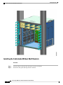
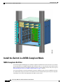
Install the Switch in a NEBS-Compliant Mode 72
NEBS-Compliant Air Filter 72
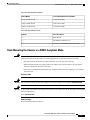
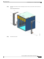
Rack-Mounting the Chassis in a NEBS-Compliant Mode 73
Establishing System Ground 81
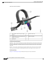
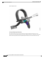
Attaching an ESD Strap 83
Cisco Catalyst 9400 Series Switches Hardware Installation Guide
iii
Contents

Verifying the Switch Chassis Installation 86
Removing and Replacing FRUs 87
CHAPTER 6
Removing and Installing a Fan Tray 87
Enabling the Service Mode Before Removing a Fan Tray 88
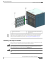
Removing a Fan Tray from the Front 88
Installing a Fan Tray from the Front 92
Removing a Fan Tray from the Rear 93
Installing a Fan Tray from the Rear 96
Verifying Fan Tray Installation 97
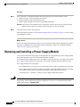
Removing and Installing a Power Supply Module 98
Removing and Installing an AC-Input Power Supply Module 100
Removing an AC-Input Power Supply Module 100
Installing an AC-Input Power Supply Module 104
Power Cord Retainer Mechanism 107
Removing and Installing a DC-Input Power Supply Module 112
Required Tools and Equipment 112
Removing a DC-Input Power Supply Module 113
Installing a DC-Input Power Supply Module 119
Removing and Installing a Power Supply Blank 127
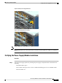
Verifying the Power Supply Module Installation 129
Troubleshooting 131
CHAPTER 7
About this Section 131
System Boot Verification 131
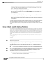
Using LEDs to Identify Startup Problems 132
System Messages 133
Troubleshooting with Software 133
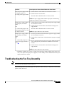
Troubleshooting a Power Supply Module 134
Useful Cisco IOS Commands - Power Supply 134
Troubleshooting an AC-Input Power Supply 134
Troubleshooting a DC-Input Power Supply 135
Restoring the Default Mode of the Power Button for a DC Power Supply Module 136
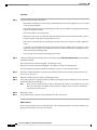
Troubleshooting the Fan Tray Assembly 137
Cisco Catalyst 9400 Series Switches Hardware Installation Guide
iv
Contents

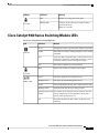
Useful Cisco IOS Commands - Fan Tray Assembly 139
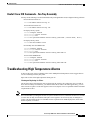
Troubleshooting High Temperature Alarms 139
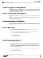
Troubleshooting the Switching Module 140
Useful Cisco IOS Commands - Switching Modules 140
Troubleshooting Supervisor Modules 140
Supervisor Module LEDs 140
Standby Supervisor Engine Problems 140
Switch Self Reset 141
Cannot Connect to a Switch Through the Console Port 141
Boot Problems 144
Contacting the Cisco Technical Assistance Center 144
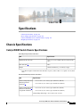
Specifications 145
CHAPTER 8
Chassis Specifications 145
Catalyst 9404R Switch Chassis Specifications 145
Catalyst 9407R Switch Chassis Specifications 147
Catalyst 9410R Switch Chassis Specifications 149
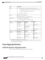
Power Supply Specifications 150
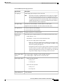
2100-W AC-Input Power Supply Specifications 150
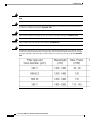
2100-W Power Supply Module AC Power Cords 152
3200-W AC-Input Power Supply Specifications 154
3200-W Power Supply Module AC Power Cords 156
3200-W DC-Input Power Supply Specifications 158
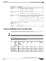
Chassis and Module Power and Heat Values 159
Weight Specifications 160
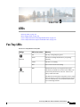
LEDs 163
CHAPTER 9
Fan Tray LEDs 163
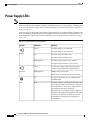
Power Supply LEDs 164
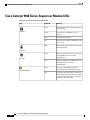
Cisco Catalyst 9400 Series Switching Module LEDs 165
Cisco Catalyst 9400 Series Supervisor Module LEDs 166
Initial Configuration for the Switch 169
CHAPTER 10
Options for Initial Configuration 169
Cisco Catalyst 9400 Series Switches Hardware Installation Guide
v
Contents

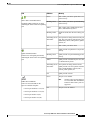
Configuring the Switch Using the Web User Interface 169
Configuring the Switch Using the CLI 170
Starting the Terminal-Emulation Software 170
Connecting to a Power Source 170
Connecting the RJ-45 Console Port 171
Connecting the USB Console Port 171
IP Settings 172
Performing the Initial Configuration 172
Configuring the Switch in the ROMMON Mode 175
Installing and Uninstalling the USB Driver 175
Installing the Cisco Microsoft Windows USB Device Driver 175
Installing the Cisco Microsoft Windows USB Driver 176
Uninstalling the Cisco Microsoft Windows USB Driver 176
Uninstalling the Cisco Microsoft Windows USB Driver 176
Related Documentation 177
CHAPTER 11
Analysis of Cabling Requirements for IEEE 802.3bt Type 4 Devices 179
APPENDIX A
Cisco Catalyst 9400 Series Switches Hardware Installation Guide
vi
Contents

CHAPTER 1
Safety Warnings
Safety warnings appear throughout this publication in procedures that may harm you if you perform them
incorrectly. A warning symbol precedes each warning statement. The warnings below are general warnings
that are applicable to the entire publication.
Power Cable and AC Adapter - When installing the product, please use the provided or designated connection
cables/power cables/AC adaptors.Using any other cables/adaptors could cause a malfunction or a fire. Electrical
Appliance and Material Safety Law prohibits the use of UL-certified cables (that have the "UL or CSA" shown
on the code) for any other electrical devices than products designated by CISCO. The use of cables that are
certified by Electrical Appliance and Material Safety Law (that have "PSE" shown on the code) is not limited
to CISCO-designated products. Statement 371
Warning
Read the installation instructions before using, installing or connecting the system to the power source.
Statement 1004
Warning
Class 1 laser product. Statement 1008
Warning
This unit is intended for installation in restricted access areas. A restricted access area can be accessed only
through the use of a special tool, lock and key, or other means of security. Statement 1017
Warning
Only trained and qualified personnel should be allowed to install, replace, or service this equipment. Statement
1030
Warning
Hazardous voltage or energy is present on the backplane when the system is operating. Use caution when
servicing. Statement 1034
Warning
Cisco Catalyst 9400 Series Switches Hardware Installation Guide
1

Ultimate disposal of this product should be handled according to all national laws and regulations. Statement
1040
Warning
Invisible laser radiation may be emitted from disconnected fibers or connectors. Do not stare into beams or
view directly with optical instruments. Statement 1051
Warning
Class 1M laser radiation when open. Do not view directly with optical instruments. Statement 1053
Warning
Class I (CDRH) and Class 1M (IEC) laser products. Statement 1055
Warning
Invisible laser radiation may be emitted from the end of the unterminated fiber cable or connector. Do not
view directly with optical instruments. Viewing the laser output with certain optical instruments (for example,
eye loupes, magnifiers, and microscopes) within a distance of 100 mm may pose an eye hazard. Statement
1056
Warning
Cisco Catalyst 9400 Series Switches Hardware Installation Guide
2
Safety Warnings

IMPORTANT SAFETY INSTRUCTIONS
This warning symbol means danger. You are in a situation that could cause bodily injury. Before you
work on any equipment, be aware of the hazards involved with electrical circuitry and be familiar with
standard practices for preventing accidents. Use the statement number provided at the end of each
warningto locate itstranslation in the translated safety warningsthat accompanied thisdevice. Statement
1071
SAVE THESE INSTRUCTIONS
Warning
Cisco Catalyst 9400 Series Switches Hardware Installation Guide
3
Safety Warnings

Cisco Catalyst 9400 Series Switches Hardware Installation Guide
4
Safety Warnings

CHAPTER 2
Product Overview
•Switch Models, on page 5
•Fan Tray Assembly, on page 17
•Power Supply Module, on page 20
Switch Models
The following sections provide detailed information about the available switch models:
Catalyst 9404R Switch
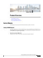
The Catalyst 9404R Switch is a four-slot modular chassis, with two redundant supervisor module slots, two
switching module slots with up to 96 front panel ports, one nonredundant fan tray assembly, and has a provision
to accommodate up to four power supply modules.
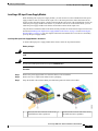
Front View of the Catalyst 9404R Switch
The figure shows a front view of the chassis, with the major components identified:
Cisco Catalyst 9400 Series Switches Hardware Installation Guide
5

Switching module slots (1,and 4)5Chassis handholds1
Chassis Radio Frequency ID (RFID)6Power supply modules2
Chassis model number7Fan tray assembly3
System ground8Supervisor module slots (2 and 3)4
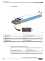
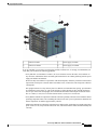
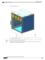
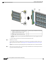
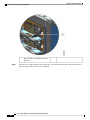
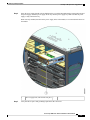
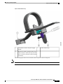
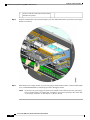
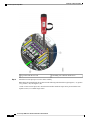
Rear View of the Catalyst 9404R Switch
The figure shows a rear view of the chassis, with the major components identified:
Cisco Catalyst 9400 Series Switches Hardware Installation Guide
6
Product Overview
Catalyst 9404R Switch

Blue beacon LED on the rear panel of the fan tray (always
matches the blue beacon on the front panel of the fan tray)
2Access to remove fan tray from the rear1
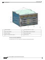
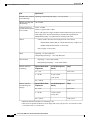
Table 1: Catalyst 9404R Switch Features
DescriptionFeature
Chassis model number (add = for spare)—Cisco Catalyst 9400 Series 4 Slot Chassis(C9404R)Product ID
Has four horizontal slots. Slots are numbered 1 (left) to 4 (right).Chassis
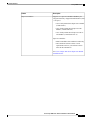
Supports 1+1 supervisor module redundancy for integrated resiliency. Supported model numbers (add = for
spare):
• Cisco Catalyst 9400 Series Supervisor 1 Module (C9400-SUP-1)
• Cisco Catalyst 9400 Series Supervisor 1XL Module ( C9400-SUP-1XL)
• Cisco Catalyst 9400 Series Supervisor 1XL-Y 25G Module (C9400-SUP-1XL-Y)
Supervisor modules:
• Must be installed in slots numbered 2 and 3 only.
• Have minimum software release version requirements. Refer to your software release notes for this
information.
See Cisco Catalyst 9400 Series Supervisor Module Installation Note.
Supervisor
modules
Cisco Catalyst 9400 Series Switches Hardware Installation Guide
7
Product Overview
Catalyst 9404R Switch

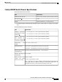
DescriptionFeature
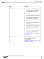
Accommodates two line cards. Supported model numbers (add = for spare):
• Cisco Catalyst 9400 Series 48-Port UPOE 10/100/1000 Module (C9400-LC-48U)
• Cisco Catalyst 9400 Series 48-Port 10/100/1000 Module (C9400-LC-48T)
• Cisco Catalyst 9400 Series 24-Port SFP/SFP+ Module (C9400-LC-24XS)
• Cisco Catalyst 9400 Series 48-Port UPOE Multigigabit Module (C9400-LC-48UX)
• Cisco Catalyst 9400 Series 48-Port SFP Module (C9400-LC-48S)
• Cisco Catalyst 9400 Series 24-Port SFP Module (C9400-LC-24S)
• Cisco Catalyst 9400 Series 48-Port Gigabit Ethernet POE/POE+ Module (C9400-LC-48P)
• Cisco Catalyst 9400 Series 48-Port Gigabit Ethernet UPOE+ 10/100/1000 Module (C9400-LC-48H)
• Cisco Catalyst 9400 Series 48-Port UPOE+ 100Mbps/1/2.5/5G Multigigabit Module (C9400-LC-48HN)
See Cisco Catalyst 9400 Series Switching Module Installation Note.
Switching
modules
The switch supports a single front and rear serviceable and hot-swappable fan tray with 8 fans.
Supported model number (add = for spare)—C9404-FAN
See Fan Tray Assembly Overview, on page 17 and Fan Tray LEDs, on page 163.
Fan tray assembly
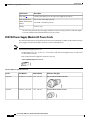
The chassis supports up to four field-replaceable AC-input and DC-input power supply modules. Supported
model numbers (add = for spare):
• C9400-PWR-2100AC
• C9400-PWR-3200AC
• C9400-PWR-3200DC
See Power Supply Module Overview, on page 20 and Power Supply LEDs, on page 164.
Power supplies
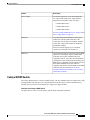
240 Gbps backplane bandwidth for each payload module slot, with the C9400-SUP-1XL or the
C9400-SUP-1XL-Y supervisor modules. With the C9400-SUP-1 supervisor module, the backplane bandwidth
is 80Gbps.
Backplane
The chassis has a built-in, front-facing, passive RFID tag that uses Ultra High Frequency (UHF) RFID technology
and requires an RFID reader with compatible software. It provides auto-identification capabilities for asset
management and tracking. The RFID tags are compatible with the Generation 2 GS1 EPC Global Standard and
are ISO 18000-6C compliant. They operate in the 860MHz to 960 MHz UHF band. For more information, see
Radio Frequency Identification (RFID on Cisco Catalyst 9000 Family Switches).
RFID Tag
Catalyst 9407R Switch
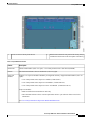
The Catalyst 9407R Switch is a seven-slot modular chassis, with two redundant supervisor module slots, five
switching module slots with up to 240 front panel ports, one non-redundant fan tray assembly, and a provision
to accommodate up to eight power supply modules.
Cisco Catalyst 9400 Series Switches Hardware Installation Guide
8
Product Overview
Catalyst 9407R Switch

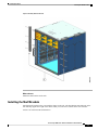
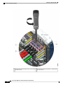
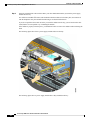
Front View of the Catalyst 9407R Switch
The figure shows a front view of the chassis, with the major components identified:
Supervisor module slots (3 and 4)5Chassis handholds1
Chassis Radio Frequency ID (RFID)6Power supply modules2
System ground7Switching module slots (1,2, 5,6, and 7)3
Chassis model number8Fan tray assembly4
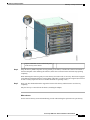
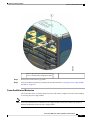
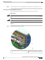
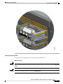
Rear View of the Catalyst 9407R Switch
The figure shows a rear view of the chassis, with the major components identified:
Cisco Catalyst 9400 Series Switches Hardware Installation Guide
9
Product Overview
Catalyst 9407R Switch

Blue beacon LED on the rear panel of the fan
tray (always matches the blue beacon on the
front panel of the fan tray)
2Access to remove fan tray from the rear1
Table 2: Catalyst 9407R Switch Features
DescriptionFeature
Chassis model number (add = for spare)—Cisco
Catalyst 9400 Series 7 Slot Chassis(C9407R)
Product ID
Has seven horizontal slots. Slots are numbered 1 (top)
to 7 (bottom)
Chassis
Cisco Catalyst 9400 Series Switches Hardware Installation Guide
10
Product Overview
Catalyst 9407R Switch

DescriptionFeature
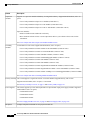
Supports 1+1 supervisor module redundancy for
integrated resiliency. Supported model numbers (add
= for spare):
• Cisco Catalyst 9400 Series Supervisor 1 Module
(C9400-SUP-1)
• Cisco Catalyst 9400 Series Supervisor 1XL
Module ( C9400-SUP-1XL)
• Cisco Catalyst 9400 Series Supervisor 1XL-Y
25G Module (C9400-SUP-1XL-Y)
Supervisor modules:
•Must be installed in slots numbered 3 and 4 only.
• Have minimum software release version
requirements. Refer to your software release
notes for this information.
See Cisco Catalyst 9400 Series Supervisor Module
Installation Note
Supervisor modules
Cisco Catalyst 9400 Series Switches Hardware Installation Guide
11
Product Overview
Catalyst 9407R Switch

DescriptionFeature
Accomodates five line cards. Supported model
numbers (add = for spare):
• Cisco Catalyst 9400 Series 48-Port UPOE
10/100/1000 Module (C9400-LC-48U)
• Cisco Catalyst 9400 Series 48-Port 10/100/1000
Module (C9400-LC-48T)
• Cisco Catalyst 9400 Series 24-Port SFP/SFP+
Module (C9400-LC-24XS)
• Cisco Catalyst 9400 Series 48-Port UPOE
Multigigabit Module (C9400-LC-48UX)
• Cisco Catalyst 9400 Series 48-Port SFP Module
(C9400-LC-48S)
• Cisco Catalyst 9400 Series 24-Port SFP Module
(C9400-LC-24S)
• Cisco Catalyst 9400 Series 48-Port Gigabit
Ethernet POE/POE+ Module (C9400-LC-48P)
• Cisco Catalyst 9400 Series 48-Port Gigabit
Ethernet UPOE+ 10/100/1000 Module
(C9400-LC-48H)
• Cisco Catalyst 9400 Series 48-Port UPOE+
100Mbps/1/2.5/5G Multigigabit Module
(C9400-LC-48HN)
See Cisco Catalyst 9400 Series Switching Module
Installation Note
Switching modules
The switch supports a single front and rear serviceable
and hot-swappable fan tray with 12 fans.
Supported model number (add = for
spare)—C9407-FAN
See Fan Tray Assembly Overview, on page 17 and
Fan Tray LEDs, on page 163
Fan tray assembly
Cisco Catalyst 9400 Series Switches Hardware Installation Guide
12
Product Overview
Catalyst 9407R Switch

DescriptionFeature
The chassis supports up to four field-replaceable
AC-input and DC-input power supply modules.
Supported model numbers (add = for spare):
• C9400-PWR-2100AC
• C9400-PWR-3200AC
• C9400-PWR-3200DC
See Power Supply Module Overview, on page 20 and
Power Supply LEDs, on page 164
Power supplies
120 Gbps backplane bandwidth for each payload
module slot with the C9400-SUP-1XL or the
C9400-SUP-1XL-Y Supervisor modules. With the
C9400-SUP-1 Supervisor module, the backplane
bandwidth is 80Gbps.
Each line card slot supports up to 32 channels
connected to each supervisor module slot.
Backplane
The chassis has a built-in, front-facing, passive RFID
tag that uses Ultra High Frequency (UHF) RFID
technology and requires an RFID reader with
compatible software. It provides auto-identification
capabilities for asset management and tracking. The
RFID tags are compatible with the Generation 2 GS1
EPC Global Standard and are ISO 18000-6C
compliant. They operate in the 860-MHz to 960-MHz
UHF band. For more information, see Radio
Frequency Identification (RFID on Cisco Catalyst
9000 Family Switches).
RFID Tag
Catalyst 9410R Switch
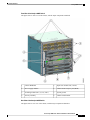
The Catalyst 9410R Switch is a ten-slot modular chassis, with two redundant supervisor module slots, eight
switching module slots with up to 384 1-Gigabit Ethernet front panel ports, one non-redundant fan tray
assembly, and a provision to accommodate up to eight power supply modules.
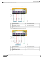
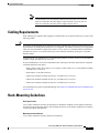
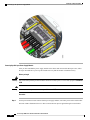
Front View of the Catalyst 9410R Switch
The figure shows a front view of the chassis, with the major components identified:
Cisco Catalyst 9400 Series Switches Hardware Installation Guide
13
Product Overview
Catalyst 9410R Switch

Supervisor module slots (5 and 6)5Chassis handholds1
Chassis Radio Frequency ID (RFID)6Power supply modules2
System ground7Switching module slots (1,2, 3, 4, 7, 8, 9 and 10)3
Chassis model number8Fan tray assembly4
Cisco Catalyst 9400 Series Switches Hardware Installation Guide
14
Product Overview
Catalyst 9410R Switch
Page is loading ...
Page is loading ...
Page is loading ...
Page is loading ...
Page is loading ...
Page is loading ...
Page is loading ...
Page is loading ...
Page is loading ...
Page is loading ...
Page is loading ...
Page is loading ...
Page is loading ...
Page is loading ...
Page is loading ...
Page is loading ...
Page is loading ...
Page is loading ...
Page is loading ...
Page is loading ...
Page is loading ...
Page is loading ...
Page is loading ...
Page is loading ...
Page is loading ...
Page is loading ...
Page is loading ...
Page is loading ...
Page is loading ...
Page is loading ...
Page is loading ...
Page is loading ...
Page is loading ...
Page is loading ...
Page is loading ...
Page is loading ...
Page is loading ...
Page is loading ...
Page is loading ...
Page is loading ...
Page is loading ...
Page is loading ...
Page is loading ...
Page is loading ...
Page is loading ...
Page is loading ...
Page is loading ...
Page is loading ...
Page is loading ...
Page is loading ...
Page is loading ...
Page is loading ...
Page is loading ...
Page is loading ...
Page is loading ...
Page is loading ...
Page is loading ...
Page is loading ...
Page is loading ...
Page is loading ...
Page is loading ...
Page is loading ...
Page is loading ...
Page is loading ...
Page is loading ...
Page is loading ...
Page is loading ...
Page is loading ...
Page is loading ...
Page is loading ...
Page is loading ...
Page is loading ...
Page is loading ...
Page is loading ...
Page is loading ...
Page is loading ...
Page is loading ...
Page is loading ...
Page is loading ...
Page is loading ...
Page is loading ...
Page is loading ...
Page is loading ...
Page is loading ...
Page is loading ...
Page is loading ...
Page is loading ...
Page is loading ...
Page is loading ...
Page is loading ...
Page is loading ...
Page is loading ...
Page is loading ...
Page is loading ...
Page is loading ...
Page is loading ...
Page is loading ...
Page is loading ...
Page is loading ...
Page is loading ...
Page is loading ...
Page is loading ...
Page is loading ...
Page is loading ...
Page is loading ...
Page is loading ...
Page is loading ...
Page is loading ...
Page is loading ...
Page is loading ...
Page is loading ...
Page is loading ...
Page is loading ...
Page is loading ...
Page is loading ...
Page is loading ...
Page is loading ...
Page is loading ...
Page is loading ...
Page is loading ...
Page is loading ...
Page is loading ...
Page is loading ...
Page is loading ...
Page is loading ...
Page is loading ...
Page is loading ...
Page is loading ...
Page is loading ...
Page is loading ...
Page is loading ...
Page is loading ...
Page is loading ...
Page is loading ...
Page is loading ...
Page is loading ...
Page is loading ...
Page is loading ...
Page is loading ...
Page is loading ...
Page is loading ...
Page is loading ...
Page is loading ...
Page is loading ...
Page is loading ...
Page is loading ...
Page is loading ...
Page is loading ...
Page is loading ...
Page is loading ...
Page is loading ...
Page is loading ...
Page is loading ...
Page is loading ...
Page is loading ...
Page is loading ...
Page is loading ...
Page is loading ...
Page is loading ...
Page is loading ...
Page is loading ...
Page is loading ...
Page is loading ...
Page is loading ...
Page is loading ...
Page is loading ...
Page is loading ...
Page is loading ...
Page is loading ...
Page is loading ...
Page is loading ...
Page is loading ...
-
 1
1
-
 2
2
-
 3
3
-
 4
4
-
 5
5
-
 6
6
-
 7
7
-
 8
8
-
 9
9
-
 10
10
-
 11
11
-
 12
12
-
 13
13
-
 14
14
-
 15
15
-
 16
16
-
 17
17
-
 18
18
-
 19
19
-
 20
20
-
 21
21
-
 22
22
-
 23
23
-
 24
24
-
 25
25
-
 26
26
-
 27
27
-
 28
28
-
 29
29
-
 30
30
-
 31
31
-
 32
32
-
 33
33
-
 34
34
-
 35
35
-
 36
36
-
 37
37
-
 38
38
-
 39
39
-
 40
40
-
 41
41
-
 42
42
-
 43
43
-
 44
44
-
 45
45
-
 46
46
-
 47
47
-
 48
48
-
 49
49
-
 50
50
-
 51
51
-
 52
52
-
 53
53
-
 54
54
-
 55
55
-
 56
56
-
 57
57
-
 58
58
-
 59
59
-
 60
60
-
 61
61
-
 62
62
-
 63
63
-
 64
64
-
 65
65
-
 66
66
-
 67
67
-
 68
68
-
 69
69
-
 70
70
-
 71
71
-
 72
72
-
 73
73
-
 74
74
-
 75
75
-
 76
76
-
 77
77
-
 78
78
-
 79
79
-
 80
80
-
 81
81
-
 82
82
-
 83
83
-
 84
84
-
 85
85
-
 86
86
-
 87
87
-
 88
88
-
 89
89
-
 90
90
-
 91
91
-
 92
92
-
 93
93
-
 94
94
-
 95
95
-
 96
96
-
 97
97
-
 98
98
-
 99
99
-
 100
100
-
 101
101
-
 102
102
-
 103
103
-
 104
104
-
 105
105
-
 106
106
-
 107
107
-
 108
108
-
 109
109
-
 110
110
-
 111
111
-
 112
112
-
 113
113
-
 114
114
-
 115
115
-
 116
116
-
 117
117
-
 118
118
-
 119
119
-
 120
120
-
 121
121
-
 122
122
-
 123
123
-
 124
124
-
 125
125
-
 126
126
-
 127
127
-
 128
128
-
 129
129
-
 130
130
-
 131
131
-
 132
132
-
 133
133
-
 134
134
-
 135
135
-
 136
136
-
 137
137
-
 138
138
-
 139
139
-
 140
140
-
 141
141
-
 142
142
-
 143
143
-
 144
144
-
 145
145
-
 146
146
-
 147
147
-
 148
148
-
 149
149
-
 150
150
-
 151
151
-
 152
152
-
 153
153
-
 154
154
-
 155
155
-
 156
156
-
 157
157
-
 158
158
-
 159
159
-
 160
160
-
 161
161
-
 162
162
-
 163
163
-
 164
164
-
 165
165
-
 166
166
-
 167
167
-
 168
168
-
 169
169
-
 170
170
-
 171
171
-
 172
172
-
 173
173
-
 174
174
-
 175
175
-
 176
176
-
 177
177
-
 178
178
-
 179
179
-
 180
180
-
 181
181
-
 182
182
-
 183
183
-
 184
184
-
 185
185
-
 186
186
-
 187
187
-
 188
188
-
 189
189
-
 190
190
-
 191
191
-
 192
192


Cisco Catalyst 9400 Series Switches Installation guide
- Type
- Installation guide
- This manual is also suitable for
Ask a question and I''ll find the answer in the document
Finding information in a document is now easier with AI
Related papers
-
Cisco Catalyst 1000 Series Switches Installation guide
-
Cisco Catalyst 9800-40 Wireless Controller Installation guide
-
Cisco PWR-C1-1100WAC Installation guide
-
-
Cisco 2523 User manual
-
-
Cisco ASR 9000 Series User guide
-
-
Cisco Catalyst 3750-X Series User manual
-
Cisco Catalyst 9300 Series Hardware Installation Manual
Other documents
-
Hubbell Wiring Device-Kellems PD2442 Installation guide
-
Cisco Systems WSUPOE12VPSPL User manual
-
 ALOCIAM B09GG7W1RJ User manual
-
Radiant T21 User manual
-
-
AC Infinity AC-TWT8 Through Wall Fan User manual
-
-
3com 871 User manual
-
OKI 9400 User manual
-
