Page is loading ...

Compac Industries Ltd.
52 Walls Road. Penrose. Auckland 1061, New Zealand.
PO Box 12 417 Penrose. Auckland 1642. New Zealand.
www.compacngv.com
Compac Industries Ltd.
52 Walls Road. Penrose. Auckland 1061, New Zealand.
PO Box 12 417 Penrose. Auckland 1642. New Zealand.
www.compacngv.com
CNG Dispenser Service Manual
Version 1.0.8

Page 2
Conditions of Use
Read this manual completely before working on, or
making adjustments to, the Compac equipment
Compac Industries Limited accepts no liability for
personal injury or property damage resulting from
working on or adjusting the CNG Dispenser
incorrectly or without authorisation.
Along with any warnings, instructions, and
procedures in this manual, you should also observe
any other common sense procedures that are
generally applicable to equipment of this type.
Failure to comply with any warnings, instructions,
procedures, or any other common sense procedures
may result in injury, equipment damage, property
damage, or poor performance of the Compac
equipment
The major hazard involved with operating the
Compac CNG Dispenser is electrical shock. This
hazard can be avoided if you adhere to the
procedures in this manual and exercise all due care.
Compac Industries Limited accepts no liability for
direct, indirect, incidental, special, or consequential
damages resulting from failure to follow any
warnings, instructions, and procedures in this
manual, or any other common sense procedures
generally applicable to equipment of this type. The
foregoing limitation extends to damages to person or
property caused by the Compac CNG Dispenser, or
damages resulting from the inability to use the
Compac CNG Dispenser, including loss of profits,
loss of products, loss of power supply, the cost of
arranging an alternative power supply, and loss of
time, whether incurred by the user or their
employees, the installer, the commissioner, a
service technician, or any third party.
Compac Industries Limited reserves the right to
change the specifications of its products or the
information in this manual without necessarily
notifying its users.
Variations in installation and operating conditions
may affect the Compac CNG Dispenser's
performance. Compac Industries Limited has no
control over each installation's unique operating
environment. Hence, Compac Industries Limited
makes no representations or warranties concerning
the performance of the Compac CNG Dispenser
under the actual operating conditions prevailing at
the installation. A technical expert of your choosing
should validate all operating parameters for each
application.
Compac Industries Limited has made every effort
to explain all servicing procedures, warnings, and
safety precautions as clearly and completely as
possible. However, due to the range of operating
environments, it is not possible to anticipate every
issue that may arise. This manual is intended to
provide general guidance. For specific guidance
and technical support, contact your authorised
Compac supplier, using the contact details in the
Product Identification section (see page v).
Information in this manual shall not be deemed a
warranty, representation, or guarantee. For
warranty provisions applicable to the Compac CNG
Dispenser, please refer to the warranty provided by
the supplier.
Unless otherwise noted, references to brand
names, product names, or trademarks constitute
the intellectual property of the owner thereof.
Subject to your right to use the Compac CNG
Dispenser, Compac does not convey any right,
title, or interest in its intellectual property, including
and without limitation, its patents, copyrights, and
know-how.
Every effort has been made to ensure the accuracy
of this document. However, it may contain technical
inaccuracies or typographical errors. Compac
Industries Limited assumes no responsibility for
and disclaims all liability of such inaccuracies,
errors, or omissions in this publication.

Page 3
Contents
Document Control Information ........................................................................................................................................ 6
Symbols and Units of Measure ........................................................................................................................................ 7
Safety ................................................................................................................................................................................. 8
Introduction ....................................................................................................................................................................... 9
Software Versions ........................................................................................................................................................... 10
Mechanical Installation ................................................................................................................................................... 11
Preparing and Cleaning Pipework .......................................................................................................................... 12
Mounting the Dispenser ......................................................................................................................................... 13
Connecting the Pipework ....................................................................................................................................... 13
Attaching the High Mast (Laser Only) .................................................................................................................... 14
Electrical Installation ...................................................................................................................................................... 15
CNG Cable Requirements ..................................................................................................................................... 15
Connecting Mains Power and Communication ...................................................................................................... 16
Electrical Commissioning .............................................................................................................................................. 17
Mechanical Commissioning ........................................................................................................................................... 18
Dispenser Set-up ............................................................................................................................................................. 19
Parameter Switch ................................................................................................................................................... 19
K-Factor Switch ...................................................................................................................................................... 25
b Configuration Code ............................................................................................................................................. 34
C Configuration Code ............................................................................................................................................ 35
Dispenser Operation ....................................................................................................................................................... 36
Refuelling a Vehicle ............................................................................................................................................... 36
Reading the Dispenser Totals ................................................................................................................................ 39
Servicing .......................................................................................................................................................................... 40
Degassing the Dispenser ....................................................................................................................................... 40
Scheduled Servicing .............................................................................................................................................. 41
Filter Element Replacement ................................................................................................................................... 47
Solenoid Valve Seal Replacement ......................................................................................................................... 48
Solenoid Coil Replacement .................................................................................................................................... 51
Complete Solenoid Valve Replacement ................................................................................................................. 52
Regulator Valve Seal Replacement ....................................................................................................................... 52
Compac Breakaway Seal Replacement ................................................................................................................. 54
Three Way Refuelling Valve Seal Replacement - Old Model -Brass ...................................................................... 55
Three Way Refuelling Valve Seal Replacement - New Model - Stainless Steel .................................................... 57
Refuelling Hose Replacement ................................................................................................................................ 59
Power Supply Fuse Replacement .......................................................................................................................... 60
Power Supply Replacement ................................................................................................................................... 61
Processor Board Replacement .............................................................................................................................. 62
Temperature Pressure Board Replacement (Fast Fill & Temperature Compensation Units Only) ........................ 63
Dispenser Software Upgrade/Replacement ........................................................................................................... 64
Meter Replacement ................................................................................................................................................ 65
Unserviceable Parts List ........................................................................................................................................ 66

Page 4
Dispenser Calibration ..................................................................................................................................................... 67
Meter Calibration .................................................................................................................................................... 67
Pressure Transducer Calibration (Fast Fill & Temperature Compensated Units Only) .......................................... 69
Ambient Temperature Sensor Calibration .............................................................................................................. 70
Indicator LEDs ................................................................................................................................................................. 71
Power, Watchdog, Comms RXD and TXD LEDs ................................................................................................... 71
Diagnostic and Output LEDs .................................................................................................................................. 72
Troubleshooting .............................................................................................................................................................. 74
Problems When Dispenser is Idle .......................................................................................................................... 75
Problems Starting a Fill .......................................................................................................................................... 76
Problems Filling a Vehicle ...................................................................................................................................... 77
Solenoid Problems ................................................................................................................................................. 79
Appendix .......................................................................................................................................................................... 80
Approvals ............................................................................................................................................................... 80
Specifications .................................................................................................................................................................. 81
Model Specifications .............................................................................................................................................. 81
Technical Specifications ........................................................................................................................................ 82
Component Specifications ..................................................................................................................................... 83
Installation Diagrams ...................................................................................................................................................... 85
LEGEND Installation Diagram ................................................................................................................................ 85
LASER Installation Diagram................................................................................................................................... 86
Dispenser Fittings .................................................................................................................................................. 87
Mechanical Drawings and Component Details ............................................................................................................. 89
Dispenser Component Locator .............................................................................................................................. 89
Hydraulic Layout .................................................................................................................................................... 90
Electrical Drawings and Component Details ................................................................................................................ 91
CNG Dispenser Electrical Schematic ..................................................................................................................... 91
C4000 Power Supply Board ................................................................................................................................... 92
C4000 Microprocessor Board ................................................................................................................................ 96
C4000 Temperature Pressure Interface Board CI75-B ........................................................................................ 112
C4000 IS Cable Connections ............................................................................................................................... 114
Dispenser spare parts................................................................................................................................................... 116
Main Dispenser Parts ........................................................................................................................................... 116
Hydraulic Module Parts ........................................................................................................................................ 119
Error Codes ................................................................................................................................................................... 120
End of Sale Indicators .......................................................................................................................................... 123

Page 5
Product Identification
Manual Title
CNG Service Manual
Original Publication Date
12/01/2010
Models Covered
Standard
High Flow
Ultra-High Flow
Laser
L-CNG15
L-CNGD15
L-CNG50
L-CNGD50
L-CNG50-15
L-CNG80
L-CNGD80
L-CNG80-15
Legend
LGDCNG15
LGDCNGD15
LE3KG25D
LGDCNG50
LGDCNGD50
LGDCNG50-15
LGDCNG80
LGDCNGD80
LGDCNG80-15
Application
Compressed Natural Gas
Power Supply
Air Supply Pressure
275 or 350 bar Max
220 - 240 VAC 50 Hz 2 Amp +/-
10%
5 to 10 bar ( Only required for units
with air actuated valves)
Related Manuals
Title
Publication Date
Owner’s Manual
September 2010
Validity
Compac Industries Limited reserves the right to revise or change
product specifications at any time. This publication describes the state of
the CNG Dispenser at the time of publication and may not reflect the
product at all times in the past or in the future.
Manufacturer Contact
Details
The Compac CNG Dispenser is designed and manufactured by:
Compac Industries Limited
52 Walls Road, Penrose, Auckland 1061, New Zealand
P.O. Box 12-417, Penrose, Auckland 1641, New Zealand
Phone: + 64 9 579 2094
Fax: + 64 9 579 0635
www.compacngv.com
Copyright ©2014 Compac Industries Limited, All Rights Reserved

Page 6
Document Control Information
Document Information and Revision History
Document Details
Compac CNG Dispenser Service Manual
File Name and Location
Current Revision Author(s)
R Lacey
Authorised By:
A.Kingstone
Release Date:27/04/11
Version
Date
Author(s)
Revision Notes
1.0.0
12/01/2010
R Lacey
Added document control information
1.0.2
08/09/2010
R Lacey
Added troubleshooting hyperlinks
1.0.3
10/02/2011
R Lacey
Added RS485 MOD-BUS & Micro Motion wiring
1.0.4
13/04/2011
R Lacey
Added RS485 wiring diagram
1.0.5
11/05/11
A.Kingstone
Corrected part numbers
1.0.6
10/02/2014
R Lacey
Added 350 Bar solenoid information
1.0.7
14/04/2014
R Lacey
Added new Temperature Pressure Board connections
1.0.8
05/05/2014
R Lacey
Added Er FLO error message
Distribution
Name
Indicator
Location

Symbols and Units of Measure
Compac Industries Ltd.
Page 7
www.compacngv.com
Symbols and Units of Measure
Symbols
Symbols are used in this manual to highlight information that is critical
to the safety of people and equipment, and for the safe and correct
operation of the Compac equipment
An extreme hazard that may result in death or injury if
proper precautions are not taken.
A reminder of safety practices or unsafe practices that
could result in personal injury or damage to associated equipment.
A reminder of safety practices or unsafe practices that
could result in damage to associated equipment and/or voids the
warranty.
Important information essential to the installation and
operation of the Compac equipment
Units of Measure
The following units of measure are used in this manual:
Unit
Measure
Pressure
Bar (bar)
Temperature
Degrees Celsius (°C)
Volume
Litres (L)
Cubic Metres (m³)
Mass
Kilograms (kg)
Length
Metres (m)
Millimetres (mm)
Microns, Micrometres (m)
Inches (")
Torque
Newton Metres (Nm)
Voltage
Volts (V)
Current
Amps (A)
Frequency
Frequency (Hz)

Safety
Compac Industries Ltd.
Page 8
www.compacngv.com
Safety
You must adhere to the following safety precautions at all times when
working on the Compac equipment. Failure to observe these safety
precautions could result in damage to the dispenser, injury, or death.
Make sure that you read and understand all safety precautions before
operating the Compac equipment
System Design
Ensure the system design does not allow the dispenser inlet
pressure to exceed its rating. The dispenser does not include any safeties
to protect against excessive inlet pressure. If necessary, suitable protective
devices should be fitted prior to the dispenser inlet.
Mechanical Safety
Observe the following electrical precautions:
Never tighten a fitting under pressure, even if a fitting or joint
is leaking. Always depressurise the line first
Never disassemble a fitting under pressure. Always
depressurise the line first
Be very careful when disassembling frozen pipework, as gas
pressure may be trapped and suddenly released. Always depressurise the
lines first.
Never reuse any O-ring seals that have been in a high
pressure gas atmosphere and then exposed to air. These o-rings swell and
cannot be reused. Always make sure you have a new seal kit available to
replace the seals before disassembly
Make sure that all internal surfaces are cleaned and that
sliding surfaces are lightly greased with O-ring lubricant before reassembly.
Dust and dirt entering components reduce the life span of the components
and can affect operation
Make sure the service area is thoroughly cleaned before
starting to service CNG components. Dust and dirt entering components
reduce the life span of the components and can affect operation
Electrical Safety
Observe the following electrical precautions:
Always turn off the power to the CNG Dispenser before
removing the box lid. Never touch wiring or components inside the CNG
Dispenser with the power on.
Never power up the CNG dispenser with the flameproof box
lid removed.
Always turn off the power to the dispenser before removing
or replacing software or memory IC's
Always take basic anti-static precautions when working on
the electronics, i.e., wearing a wristband with an earth strap.

Introduction
Compac Industries Ltd.
Page 9
www.compacngv.com
Introduction
The Compac CNG dispenser is designed to provide safe and reliable
dispensing of CNG fuels. They are available in either single or dual hose
configurations and with different flow rates.
Compac CNG dispensers are controlled by a C4000 board which has many
programmable features to suit your individual operation.
This manual contains the information required to operate and maintain your
dispenser. Due to ongoing improvements and customised designs, there
may be software features that are not available on your particular unit.
For clarity, this manual will refer to the "Dollars" display. If you do not use
dollars please substitute this for your local currency.

Software Versions
Compac Industries Ltd.
Page 10
www.compacngv.com
Software Versions
Software Version HIA29.24.9CNG
onwards
Displays error 9 messages in new format: PAUSE flashes in the kg
display and the error 9 type is shown in the unit price display.
Self checking for Error 9 faults while dispenser is idle. Displays
message if fault occurs and clears message 10 seconds after fault
clears.
During fill if error 9 fault occurs the fill will stop and the error 9
message displayed for at least 120 seconds. If fault is cleared the
display will continue for another 10 seconds.
If the dispenser is re-powered after an error 9 fault, the message will
show for 10 seconds after the start up PAUSE message.
When using the parameter switch, the hose number (PN) display has
been modified to also display a count of the total error 9 faults in the
unit shown in the price display. Refer Parameter Switch (see page 19)
In the same mode, the display will also flash in the price/kg screen, the
last recorded reason for the end of sale and the last recorded error 9.
Software Version HIA29.25.3CNG
onwards
Removing the decimal place from the totes screen
Quick view of totes by rapidly pressing the start button three times
Modification of error 9 codes to improve diagnostics
Changed sequencing rates
Sequencing triggered by minimum flow rates
Error 7 message changed to read Er Flo in totes screen
End of sale reason flashed in unit price display at end of sale
Software Version HIA29.26.0CNG
onwards
Kilograms dispensed display increased to three decimal places for
greater accuracy

Mechanical Installation
Compac Industries Ltd.
Page 11
www.compacngv.com
Mechanical Installation
Overview
The stages of mechanical installation include:
Preparing and cleaning the pipework (see page 12).
Mounting the dispenser (see page 13).
Connecting the pipework (see page 13).
Special Precautions
Ensure the system design does not allow the dispenser inlet
pressure to exceed its rating. The dispenser does not include any safety
mechanisms to protect against excessive inlet pressure. If necessary,
suitable protective devices should be fitted prior to the dispenser inlet.
Ensure you use the correct SAE thread on the inlet pipework
and do not use thread tape.
Take all possible steps to prevent water or dirt from entering
the system, both during installation and in the future. Water and dirt blocks
up the pipework, which can damage seals, and stop gas from flowing and
valves from operating.
At 200 bar of pressure, water freezes at 15°C in natural gas,
causing ice particle contamination that may damage equipment. Make
surethe pipework is clean and dry before connection.
Seals that have been damaged by moisture, methanol,
impurities, dirt slag etc, are not covered by warranty.
During installation, potential sources of water include:
Inlet gas.
Testing new inlet gas pipework with water, or allowing water to enter
the pipework before making the final connections.
Pumping the storage with air.
Allowing water to enter the high-pressure gas lines during installation.
If the inlet gas is likely to be saturated, install a gas drier into the
compressor inlet to ensure a dew point of –32°C at 250 bar of pressure.
Do not use methanol as an anti-freeze. If used in the wrong
concentrations, it causes freezing. It is also absorbs water, which can be
more damaging than the water that was originally present.
Pipework
Check the high points and low points of the
pipework distribution system to make sure
that:
Vents have been provided on all high
points.
Drains have been provided on all low
points.

Preparing and Cleaning Pipework
Mechanical Installation
Compac Industries Ltd.
Page 12
www.compacngv.com
Preparing and Cleaning Pipework
This section provides a guide to current best practice in preparing the distribution
pipework that will be connected to the Compac Dispenser.
For new stations, flush the gas feed lines thoroughly to remove all welding slag,
moisture, and impurities that may be present in the system.
Any steel, brass, or other impurities can damage the regulator and solenoid valve
seals.
The pipework installer is responsible for installing all pipework to
the dispenser with due diligence. Compac is not responsible for any pipework
external to the dispenser.
Ensure that all pipework is completely clean. Any dirt trapped in the
pipework can damage the valve seals and surfaces.
Clean and Degrease the
Pipework
To clean and degrease the pipework:
To prepare pipework, purge the pipework with nitrogen at 200 bar vented to the
atmosphere to remove dirt, moisture, and water.
1. Mix together a 10% hydrochloric acid solution, to which you have added 25%
to 50% ammonia bi-fluoride and heat to a minimum of 65°C.
Wear adequate safety gear and take adequate precautions when
using chemicals. Clean up all spills in compliance with the local territory authority
laws and regulations.
2. Circulate the mixture through the pipework for four hours or more, depending
on the condition of the pipework.
3. Drain the acid solution from the pipework.
4. Blow out the pipework with compressed air.
5. Flush the pipework with clean water until the pH value is neutral.
Neutralise the Pipework
To neutralise the pipework:
1. Pass a 25% citric acid solution through the pipework once, or dry out the
pipework by blowing hot air through it.
Wear adequate safety gear and take adequate precautions when
using chemicals. Clean up all spills in compliance with the local territory authority
laws and regulations.
2. Fill the pipework with seal oil, then drain.
3. Blow out the pipework with compressed air.
4. Blast the pipes with nitrogen at 200 bar, letting the gas expand through the
pipes.
5. Once the pipework is cleaned, seal off the system to ensure no water, dirt or
other contaminates can re-enter the pipework.
Keep the pipework venting open to the atmosphere and feed in the
200 bar of nitrogen to achieve maximum velocity.
Take care to keep pipe openings closed until the compressor is
started. This prevents rusting of the pipework, and stops dirt from entering.

Mechanical Installation
Mounting the Dispenser
Compac Industries Ltd.
Page 13
www.compacngv.com
Mounting the Dispenser
The mounting points on the dispenser differ depending on whether you are
installing a Legend or a Laser. Installation Diagrams (see page 85)
To mount the dispenser:
1. Make sure that the dispenser is located on a solid, horizontal foundation or
plinth.
2. Seal the supply pipes to prevent dirt, moisture, or water from entering
during the mounting process.
3. Mark out the mounting points on the foundation, using the correct footprint
diagram for the model of dispenser being installed.
See the Legend or Laser footprint diagrams below. Installation Diagram
(see page 85)
4. Secure the dispenser with 12 mm dynabolts and washers. 12 mm
dynabolts have the required strength to hold the unit but up to 16 mm x 75
mm dynabolts can be used in the 20 mm footprint holes.
Connecting the Pipework
1. Make sure that your work area (including the vice, workbench, tool storage
area, and floor) is totally clean of particles or previous work. Cleanliness
and correct assembly practice can avoid most seal problems.
2. Make sure that the gas inlet pipes are properly supported before
connection.
3. Refer to one of the following procedures, depending on the fitting that you
are using:
SAE Fittings (see page 87)
Adjustable SAE fittings (see page 87)
Compression tube Fittings (see page 88)

Attaching the High Mast (Laser Only)
Mechanical Installation
Compac Industries Ltd.
Page 14
www.compacngv.com
Attaching the High Mast (Laser Only)
All high masts come pre-assembled with the dispenser and simply require
connection.
To attach the high mast:
1. Remove the stainless steel screws from the side of the dispenser.
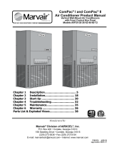
2. Attach the mast using the screws, as pictured below.
The high mast gasket and stainless steel screws are fitted
to the dispenser in the factory.
High mast assembly
complete with
bracket
High mast gasket
Side of display cabinet
High mast
reinforcing bracket
3 x M8 x 30 stainless steel
socket head screw
(6 mm Allen or Hex
key required for installation)
3 x M8 x 30 stainless steel
socket head screw
(6 mm Allen or Hex
key required for installation)
3 x M8 spring washers
3 x M8 flat washers

Electrical Installation
CNG Cable Requirements
Compac Industries Ltd.
Page 15
www.compacngv.com
Electrical Installation
CNG Cable Requirements
Cable requirements are as follows:
Cable Type
Requirement
Power
3 Core Steel Wire Armour Cable 2.5mm2,
220 - 240 Volts. 50 Hz, +/-10%
Core 1: 230 Volt Supply (Active).
Core 2: Neutral.
Core 3: Earth.
Power Consumption
25w Idle, 200W with all solenoids active.
Comms
Standard comms: 2 Core Steel Wire Armour Cable 1.5 mm2. Maximum
cable length 100 m. 12 V current loop.
Optional RS485 comms: 4 core Steel Wire Armour (SWA) 1.5 mm two
twisted pair.
Make sure that there is at least a two metre cable tail on both
the incoming underground 230 V and comms cables to reach the C4000
flameproof box.

Connecting Mains Power and Communication
Electrical Installation
Compac Industries Ltd.
Page 16
www.compacngv.com
Connecting Mains Power and Communication
In sites where the electrical supply is unstable, it is
recommended that a power conditioner or UPS is installed.
To connect the dispenser:
1. Wire the power and comms to the C4000 Termination Board, as shown
in the diagram below.
2. Connect the earth lead of the supply cable to the earth stud in the
flameproof junction box.
All cables must be terminated with approved flameproof
glands. The thread is 20 mm.
Figure 1. C4000 Power supply wiring

Electrical Commissioning
Compac Industries Ltd.
Page 17
www.compacngv.com
Electrical Commissioning
This procedure outlines how to perform an electrical operational test
before carrying out full mechanical commissioning, making sure that the
dispenser is functioning correctly. Check for any damage that may have
occurred in transit. Check all terminals, plugs, and chips to make sure
that they are securely in place.
Damage to electronics occurs most commonly from
vibration and jarring.
Before beginning this test, check that no gas pressure has been applied
to the dispenser inlets. The factory set-up information should be
programmed into the dispenser but all K-factor and Parameter switch
settings should be checked and confirmed before commissioning tests
are carried out.
To perform an electrical operational test:
1. Make sure that the inlet shut-off valves are closed (these are the
valves in the inlet lines at the base of the dispenser, but they are not
part of the dispenser).
2. Turn on the power supply to the dispenser.
The displays and backlighting will illuminate, and the displays read
PA:uS:E, then count down for one minute.
The dispenser is in a ready state once the countdown is finished
and the display shows 0.00.
3. With the dispenser in a ready state, check that the C4000
Microprocessor Power LED (D1) is turned on
If the dispenser is receiving information, Comms RXD
LED (D6) will poll. If the dispenser responds to polls for its
respective pump number/s, Comms TXD LED (D7) will also poll.
Diagnostic LED (D18) slowly flashing. (If the dispenser is
connected to an operational Controller, it flashes slowly but
erratically. If the dispenser is not connected to a Controller, it
flashes slowly and consistently.)
Watchdog LED (D5) is turned off
4. Press the Start button.
The display will show 888888 and the solenoids energise, initiating
a fill. Check that Diodes D8, D10 and D11 turn on, indicating a
signal is being sent to the triacs to open the solenoid valves.
The diagnostic LED (D18) flashes quickly when the start button is
pushed or the nozzle removed from the holster to initiate a fill. When
the button is released or nozzle returned to the holster it will return
to the normal state and flash slowly.
5. Verify solenoid operation by listening for a click, or by using a
screwdriver tip or some other metallic tool to check for a magnetic
field present on the solenoid coils.
The solenoids will switch off after one minute. This is a default time-
out setting in the software for situations when there is no gas flow
registered.
6. Press the Stop button. The solenoids switch off and the fill ends.
When you release the Stop button, the dispenser resets and returns
to a ready state.

Mechanical Commissioning
Compac Industries Ltd.
Page 18
www.compacngv.com
Mechanical Commissioning
At the mechanical commissioning stage, the dispenser should not be
pressurised.
If you find any leaks during commissioning, immediately close
all of the valves and de-gas the dispenser (see page 40).
To perform a mechanical test:
1. Make sure that the inlet shut-off valves are closed. (These are the
valves in the inlet lines at the base of the dispenser, but they are not
part of the dispenser.)
2. Check all dispenser fittings, especially the inlet connections, to make
sure that they are tight.
Always de-gas the lines before tightening any fittings.
Never tighten fittings while they are under pressure.
3. Check that the outlet supply valve to hose 1 on the side of the
dispenser (or hose 2 if you are working on side 2) is closed and the
nozzle valve is closed.
4. Turn on the dispenser and wait for it to power up.
The dispenser initially displays PA:uSE. When it is ready, 0.00 is
displayed.
5. Press the Start button.
If you are commissioning a dual hose dispenser, press
the Start button on either side. This opens the dispenser's solenoids.
The dispenser automatically shuts off after approximately one minute if
no flow is detected.
6. Slowly open the inlet shut-off valves and listen for leaks. If you hear
leakage, shut off the inlets immediately. If the dispenser shuts off
during this process, shut off the inlet valves, restart the dispenser, and
continue.
7. Once the inlet valves are fully open, allow the dispenser to time out on
the 1 minute no-flow timer and shut the solenoid valves, or manually
shut it down and close the solenoid valves by pressing the Stop button.
8. Press the Start button on the dispenser.
If you are commissioning a dual hose dispenser, only
press the Start button for one of the hoses.
9. Slowly open the outlet isolation valve on the side of the dispenser and
listen for leaks. If you hear leakage, shut the valve immediately.
If the dispenser shuts off during this process then shut the outlet supply
valve, restart the dispenser, and continue.
10. Repeat steps 8 and 9 for the second hose on a dual hose dispenser.
11. Once the outlet isolation valves are fully open, allow the dispenser to
time out on the 1 minute no-flow timer and shut the solenoid valves, or
manually shut it down and close the solenoid valves by pressing the
Stop button.
The dispenser and hose(s) are now fully pressurised.
12. Use soapy water to check all fittings (including the hose fittings) for
leaks.
Always de-gas the lines before tightening any fittings.
Never tighten fittings while they are under pressure.
13. Complete a few fills on a test cylinder, checking for leaks or unusual
operation.

Dispenser Set-up
Parameter Switch
Compac Industries Ltd.
Page 19
www.compacngv.com
Dispenser Set-up
Parameter Switch
The Parameter switch is located on the C4000
processor board and allows you to adjust the
unit price, hose number, sequencing rate, and
password.
The Parameter switch also enables you to view
the Dispenser Software Version and End of
Sale Indicators.
Figure 2: Parameter and K-Factor
switches.

Parameter Switch
Dispenser Set-up
Compac Industries Ltd.
Page 20
www.compacngv.com
Menu Options
Menu Options
Listed below is the order in which the Parameter switch menu options are
presented. There are different menu options depending on the current
setting of the C configuration code (see page 35).
The X indicates that you can achieve the displayed menu option,
regardless of what the indicated part is set to. You may need to change the
C configuration in order to access the parameter code you require.
C Configuration
Set-Up Code
Code Description
CXXX61
P
Software Program version
Pr
Unit Price
SE9
CNG Sequencing rate
(FAS,nOr,SLO)
Pn
Hose Number
Code
Dispenser Passcode
CXXX62
P
Software Program version
PrA
Unit Price Side A
PrB
Unit Price Side B
PnA
Hose Number Side A
PnB
Hose Number Side B
Code
Dispenser Passcode
Dispenser Software Version
The dispenser software version (P) is the version number of the software
currently loaded in the dispensers C4000.
See Dispenser Software Upgrade/Replacement (see page 64) for
instructions on Upgrading dispenser software
To Identify the Software Program Version
Number
1. Make sure that the dispenser is idle, with the nozzle in its holster.
2. Press and release the Parameter switch once or until P is displayed.
The system enters a diagnostic mode whereby it displays the software
program version and performs a display segment test. It cycles through
this program for approximately 10 seconds before reverting to the
normal display.
When displaying program version data, the display panel shows P in the
Dollars screen and XXXXX, in the Kilograms screen where XXXXX is the
abbreviated program version number. For example: Software version
HIA29.26.0CNG will read 29260
/