
®
PN 688744
February, 1998
© 1998 Fluke Corporation, Inc. All rights reserved. Printed in U.S.A.
All product names are trademarks of their respective companies.
5520A
Multi-Product Calibrator
Programmers Guide


1
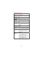
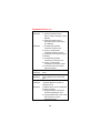
Table of Contents
Types of Commands ........................................... 3
Device-Dependent Commands......................... 3
Common Commands ....................................... 3
Query Commands ............................................ 3
Compound Commands..................................... 3
Coupled Commands ........................................ 3
Overlapped Commands ................................... 3
Sequential Commands..................................... 3
Commands for RS-232 Only............................. 3
Command Syntax................................................ 4
General Syntax Rules ...................................... 4
Units Accepted in Parameters and Responses. 5
Incoming Character Processing ....................... 6
Terminator Characters ..................................... 7
Response Message Data Types....................... 7
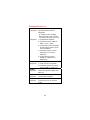
Checking 5520A Status ....................................... 8
Status Register Summary ................................ 8
STB and SRE .................................................. 9
ESR and ESE ................................................ 10
ISR, ISCE, and ISCR ..................................... 11
Service Request Enable Register (SRE) ........ 12
Output Queue ................................................ 12
Error Queue................................................... 12
Command Summary.......................................... 13
Common Commands ..................................... 13
Error Mode Commands .................................. 14
External Connection Commands .................... 15
Oscilloscope Commands................................ 16
Output Commands......................................... 18
Pressure Measurement Commands ............... 20
RS-232 Host Port Commands ........................ 21
RS-232 UUT Port Commands ........................ 21
Setup and Utility Commands.......................... 22
Status Commands ......................................... 24
Thermocouple (TC) Measurement Commands 25
Command List ................................................... 26

2
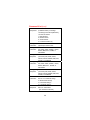
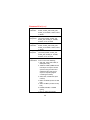
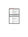
Warning
The 5520A Calibrator (hereafter
referred to as “The Calibrator”) can
produce voltages up to 1000 V rms and
must be programmed with caution to
prevent hazardous voltages from being
produced without sufficient warning to
the operator.
Write programs carefully and test them
extensively to ensure safe operation of
the Calibrator. Fluke suggests that you
include error-catching routines in your
programs. These error-catching
routines will help you identify
programming errors that may cause the
calibrator to behave other than
intended. You can program the
Calibrator to cause an SRQ when an
error is detected by setting the Service
Request Enable (SRQ) register. The
following skeleton program includes
error-catching code:
10 PRINT @4, “*CLS” ! Clear status
20 PRINT @4, “*SRE 8” ! Set SRE Error Avail.
30 ON SRQ GOTO 1000 ! Enable SRQ Function
100 ! Body of program here
900 STOP ! End of program
1000 REM Start of SRQ Handler ! Start routine
1010 PRINT @4, “FAULT?” ! Request fault code
1020 INPUT @4, A% ! Input fault code
1030 PRINT @4, “EXPLAIN? ”;A%! Request fault text
1040 INPUT @4, A$ ! Input fault text
1050 PRINT “Fault ”;A$“ detected” ! Print message
1060 PRINT @4, “STBY” ! Place 5520A in standby
1070 STOP

3
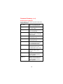
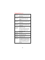
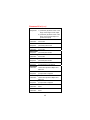
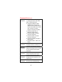
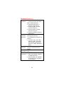
Types of Commands
Device-Dependent Commands
Commands unique to 5520A.
Common Commands
Commands defined by the IEEE 488.2 standard.
Query Commands
Commands ending with a ?.
Compound Commands
Two or more commands in a single command line.
Coupled Commands
Commands that could interfere with each other.
Overlapped Commands
Commands requiring more time to execute.
Sequential Commands
Commands that execute immediately.
Commands for RS-232 Only
IEEE-488 RS-232 Equivalent
GTL LOCAL command
GTR REMOTE command
LLO LOCKOUT command
SRQ SRQSTR command
SDC, DCL ^C (<Ctrl> C) character [clear the
device]
GET ^T (<Ctrl> T) character [execute a
group trigger]
SPE, SPD ^P (<Ctrl> P) character [print the
serial poll string]
Also: SP_SET SPLSTR SRQSTR
SP_SET? SPLSTR? SRQSTR?

4
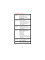
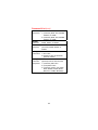
Command Syntax
General Syntax Rules
1. Separate parameters with commas.
2. Numeric parameters up to 15 significant digits
and exponents in the range ±1.0E ± 20.
3. Null parameters cause an error, e.g., the
adjacent commas in OUT 1V, ,2A.
4. Expressions, for example 4 + 2 ∗ 13, are not
allowed as parameters.
5. Binary Block Data can be in one of two IEEE
488.2 formats:
Indefinite Length Format Accepts data bytes
after #0 until the ASCII Line Feed character is
received with an EOI signal (for RS-232, a line
feed or carriage return will terminate the block).
Definite Length Format The data bytes are
preceded by #n and an n-digit number, which
identifies how many data bytes follow.
6. One space after a command is required. You
can insert extra spaces or tabs between
commands and arguments.

5
Command Syntax (cont)
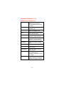
Units Accepted in Parameters and
Responses
Units Meaning
HZ Frequency in hertz
KHZ Frequency in kilohertz
MHZ Frequency in megahertz
UV Volts in microvolts
MV Volts in millivolts
V Volts in volts
KV Volts in kilovolts
UA Current in microamperes
MA Current in milliamps
A Current in amps
PCT Percent
PPM Parts-per-million
DBM Volts in decibels referenced to 1
milliwatt into 600Ω load
OHM Resistance in ohms
KOHM Resistance in kilohms
MOHM Resistance in megohms
NF Capacitance in nanofarads
PF Capacitance in picofarads
UF Capacitance in microfarads
MF Capacitance in millifarads
F Capacitance in farads
CEL Temperature in degrees Celsius
FAR Temperature in degrees Fahrenheit

6
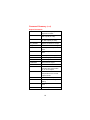
Command Syntax (cont)
Units Accepted in Parameters and
Responses (cont)
Units Meaning
NS Period in nanoseconds
US Period in microseconds
MS Period in milliseconds
S Period in seconds
PSI Pressure in pound-force per square
inch
MHG Pressure in meters of mercury
INHG Pressure in inches of mercury
INH2O Pressure in inches of water
FTH2O Pressure in feet of water
MH2O Pressure in meters of water
BAR Pressure in bar
PAL Pressure in pascal
G/CM2 Pressure in grams per centimeter
squared
INH2O60F Pressure in inches of water at 60
degrees Fahrenheit
Incoming Character Processing
1. The most significant data bit (DIO8) is ignored.
2. All data is taken as 7-bit ASCII.
3. Lower-or upper-case characters.
4. ASCII characters less than 32 (Space) are
discarded, except for characters 10 (LF) and
13 (CR), and in the *PUD command argument.

7
Command Syntax (cont)
Terminator Characters
ASCII
Function # Code Control C Code
Carriage
Return
13 Chr(13) <Ctrl> M \n
Line Feed 10 Chr(10) <Ctrl> J \r
Backspace 8 Chr(8) <Ctrl> H \b
Form Feed 12 Chr(12) <Ctrl> L \f
EEE-488 Interface The Calibrator sends the
ASCII character Line Feed with the EOI control
line held high as the terminator for response
messages.
RS-232 Interface The Calibrator returns an EOL
(End of Line) character with each response,
selectable as CR, LF or both CRLF.
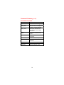
Response Message Data Types
Data Type Description
Integer Decimal numbers to 32768.
Floating Numbers plus an exponent.
String ASCII characters within
double or single quotes
(“string” or ‘string’).
Binary Block Data Defined by the IEEE-488.2.

8
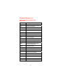
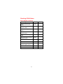
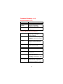
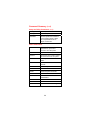
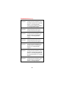
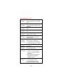
Checking 5520A Status
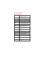
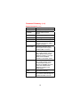
Status Register Summary
Status Register Read Write
Serial Poll Status Byte
(STB)
*STB?
Service Request Enable
Register (SRE)
*SRE? *SRE
Event Status Register
(ESR)
*ESR?
Event Status Enable
Register (ESE)
*ESE? *ESE
Instrument Status Register
(ISR)
ISR?
Instrument Status Change
Register (ISCR)
ISCR?
ISCR 1 to 0 transition ISCR0?
ISCR 0 to 1 transition ISCR1?
Instrument Status Change
Enable Register (ISCE)
ISCE? ISCE
ISCE 1 to 0 transition ISCE0? ISCE0
ISCE 0 to 1 transition ISCE1? ISCE1

9
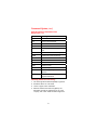
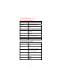
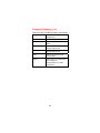
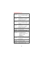
Checking 5520A Status (cont)
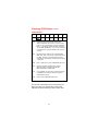
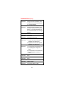
STB and SRE
76543210
0 RQS
MSS ESB MAV EAV ISCB 0 0
RQS
MSS
ESB
MAV
EAV
ISCB
Requesting service. The RQS bit is set to 1
whenever bits ESB, MAV, EAV, or ISCB change
from 0 to 1 and are enabled (1) in the SRE. When
RQS is 1, the 5520A asserts the SRQ control line
on the IEEE-488 interface. You can do a serial poll
to read this bit to see if the 5520A is the source of
an SRQ.
Master summary status. Set to 1 whenever bits
ESB, MAV, EAV, or ISCB are 1 and enabled (1) in
the SRE. This bit can be read using the *STB?
command in serial remote control in place of doing
a serial poll.
Set to 1 when one or more enabled ESR bits are 1.
Message available. The MAV bit is set to 1
whenever data is available in the 5520A’s
IEEE-488 interface output buffer.
Error available. An error has occurred and an error
is available to be read from the error queue by
using the ERR? query.
One or more enabled ISCR bits are 1.
ol01f.eps
For RS-232, transmitting the ^P character (hold
down the <Ctrl> key and press P) returns the
SPLSTR (Serial Poll String) and the status byte.

10
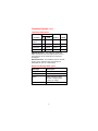
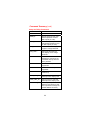
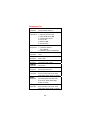
Checking 5520A Status (cont)
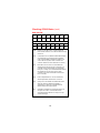
ESR and ESE
PON
CME
EXE
DDE
QYE
OPC
Power on. This bit is set to 1 if line power has
been turned off and on since the last time the ESR
was read.
Command error. The 5520A’s IEEE-488 interface
encountered an incorrectly formed command.
(The command ERR? fetches the earliest error
code in the error queue, which contains error
codes for the first 15 errors that have occurred.)
Execution error. An error occurred while the
5520A tried to execute the last command. This
could be caused, for example, by a parameter
being out of range. (The command ERR? fetches
the earliest error in the error queue, which
contains error codes for the first 15 errors that
have occurred.)
Device-dependent error. An error related to a
device-dependent command has occurred.
Query error. The 5520A was addressed to talk
when no response data was available or
appropriate, or when the controller failed to
retrieve data on the output queue.
Operation complete. All commands previous to
reception of a *OPC command have been
executed, and the interface is ready to accept
another message.
15 14 13 12 11 10 9 8
00000000
76543210
PON 0 CME EXE DDE QYE 0 OPC
ol02f.eps

11
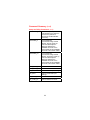
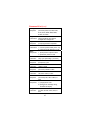
Checking 5520A Status (cont)
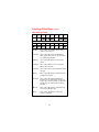
ISR, ISCE, and ISCR
RPTBUSY
SETTLED
REMOTE
UUTBFUL
UUTDATA
HIVOLT
MAGCHG
TMPCAL
OPER
Set to 1 when a calibration report is being
printed to the serial port.
Set to 1 when the output has stabilized to
within speclfication or the TC measurement
has settled and is available.
Set to 1 when the 5520A is under remote
control.
Set to 1 when data from the UUT port has
filled up the UUT buffer.
Set to 1 when there ia data available from the
UUT port.
Set to 1 when the 5520A is programmed to a
voltage above 33 Volts.
Set to 1 when the output magnitude has
changed as a result of another change (e.g.
RTD_TYPE). This bit is always 0 in the ISR. It
changes to 1 only in the ISCR0 and ISCR1
registers.
Set to 1 when the 5520A is using temporary
(non-stored) calibration data.
Set to 1 when the 5520A is in operate, 0
when it is in standby.
15 14 13 12 11 10 9 8
00 0
76543210
0000
ol03f.eps

12
Checking 5520A Status (cont)
Service Request (SRQ) Line
IEEE-488 Bus control line that asserts to notify
the controller that it requires some type of service.
RS-232 Sends the SRQSTR string over the serial
interface when service is required.
Service Request Enable Register (SRE)
The SRE enables or masks the bits of the Serial
Poll Status Byte. The SRE is cleared at power up.
Output Queue
Whenever a query is processed, the output queue
is loaded. If the queue is empty, the Calibrator
does not respond to the INPUT statement. The
Message Available (MAV) bit in the Serial Poll
Status Byte is 1 if there is something in the output
queue and 0 if the output queue is empty. The
output queue contains a maximum of 800
characters.
Error Queue
Whenever a command error, execution error, or
device-dependent error occurs, its error code is
placed in the error queue where it can be read by
the ERR? command. The error queue contains a
maximum of 16 entries.

13
Command Summary
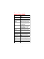
Common Commands
*CLS Clears ESR, ISCR0, ISCR1, error
queue, RQS, and terminates
pending *OPC or *OPC?
*ESE Loads ESE register.
*ESE? Returns ESE contents.
*ESR? Returns ESR contents.
*IDN? Returns instrument identification.
*OPC Sets OPC bit in ESR to 1 when
device operations are complete.
*OPC? Returns 1 after operations are done.
*OPT? Returns hardware/software
options.
*PUD Stores a string in nonvolatile
memory.
*PUD? Returns contents of *PUD
memory.
*RST Resets to power-up state.
*SRE Loads SRE register.
*SRE? Returns SRE contents.
*STB? Returns the status byte.
*TRG Triggers a measurement return
value.
*TST? Initiates self test; return 0 for
pass.
*WAI Waits until commands are
executed.

14
Command Summary (cont)
Error Mode Commands
EDIT Sets edit field.
EDIT? Returns edit field setting.
ERR_UNIT Sets the UUT error display unit
or ppm/% change threshold.
ERR_UNIT? Returns the selected UUT
error display unit or change
threshold.
INCR Increments or decrements
output.
MULT Multiplies reference
magnitude.
NEWREF Sets reference to output value.
OLDREF Sets output to previous
reference.
OUT_ERR? Returns UUT computed error.
REFOUT? Returns reference value.

15
Command Summary (cont)
External Connection Commands
CUR_POST Selects terminals for current
output.
CUR_POST? Returns terminals for current
output.
EARTH Selects earth ground is isolated
or tied.
EARTH? Returns earth ground isolated
or tied.
EXTGUARD Connects or disconnects the
internal guard shield from the
LO binding post.
EXTGUARD? Returns whether the internal
guard shields are connected
or disconnected from earth
(chasis) ground.
LOWS Selects low terminals open or
tied.
LOWS? Returns low terminals open or
tied.
RTD_TYPE Sets RTD sensor type.
RTD_TYPE? Returns RTD sensor type.
TC_REF Sets internal/external reference
value.
TC_REF? Returns TC reference value.
TC_TYPE Sets TC sensor type.
TC_TYPE? Returns TC sensor type.
TSENS_TYPE Sets temperature sensor type.
TSENS_TYPE? Returns temperature sensor
type.

16
Command Summary (cont)
Oscilloscope Commands
See Chapter 8 of the 5520A Operators Manual for
usage information.
OL_TRIP? Returns the detected state of
scope overload protection.
OUT_IMP Sets the output impedance of
the SCOPE BNC.
OUT_IMP? Returns the output impedance
of the SCOPE BNC.
RANGE Sets the 5520A range when in
OVERLD, PULSE, or MEASZ
scope modes.
SCOPE Sets the calibrator output to an
oscilloscope mode.
SCOPE? Returns the present
oscilloscope mode.
TDPULSE Activates or deacvitates the
tunnel diode pulser drive for
the -SC600 EDGE mode.
TDPULSE? Returns whether the tunnel
diode pulser drive for the
-SC600 EDGE mode is active.
TLIMIT Sets the time limit for -SC600
OVERLD mode to stay in
operate.
TLIMIT? Returns the time limit for
-SC600 OVERLD mode to
stay in operate.
TLIMIT_D Sets the power-up and reset
default for the time limit for
-SC600 OVERLD mode to
stay in operate.

17
Command Summary (cont)
Oscilloscope Commands (cont)
TLIMIT_D? Returns the power-up and reset
default for the time limit for
-SC600 OVERLD mode to stay
in operate.
TMWAVE Selects the waveform for
MARKER mode.
TMWAVE? Returns the timemark waveform
setting for MARKER mode.
TRIG Sets the frequency of the signal
at the TRIG OUT BNC.
TRIG? Returns the frequency of the
signal at the TRIG OUT BNC.
VAL? Returns the last thermocouple,
pressure, or, for the -SC600,
impedance measurement value.
VIDEOFMT Selects the format for VIDEO
mode.
VIDEOFMT? Returns the VIDEO mode format.
VIDEOMARK Sets the VIDEO mode line
marker location.
VIDEOMARK? Returns the VIDEO mode line
marker location.
ZERO_MEAS Zeros the pressure module or
sets the zero offset for
capacitance measurement using
the -SC600.
ZERO_MEAS? Returns the zero offset for the
pressure module or capacitance
measurement using the -SC600.

18
Command Summary (cont)
Output Commands
CFREQ? Returns the frequency for
capacitance modes.
DBMZ Sets the impedance used for
dBm outputs (ac volts).
DBMZ? Returns the impedance used
for dBm outputs (ac volts).
DC_OFFSET Applies dc offset to ac output.
DC_OFFSET? Returns the dc offset voltage.
DPF Sets displacement power
factor.
DPF? Returns displacement power
factor.
DUTY Sets squarewave duty cycle.
DUTY? Returns duty cycle.
FUNC? Returns output function.
HARMONIC Sets harmonic output.
HARMONIC? Returns harmonic location.
LCOMP Activates or deactivates
inductive load compensation
for ac current output.
LCOMP? Returns whether inductive load
compensation for ac current
output is active.
OPER Activates 5520A output.
OPER? Returns operate/standby
setting.
OUT Sets output and reference
point.
OUT? Returns output.
Page is loading ...
Page is loading ...
Page is loading ...
Page is loading ...
Page is loading ...
Page is loading ...
Page is loading ...
Page is loading ...
Page is loading ...
Page is loading ...
Page is loading ...
Page is loading ...
Page is loading ...
Page is loading ...
Page is loading ...
Page is loading ...
Page is loading ...
Page is loading ...
Page is loading ...
Page is loading ...
Page is loading ...
Page is loading ...
Page is loading ...
Page is loading ...
Page is loading ...
Page is loading ...
-
 1
1
-
 2
2
-
 3
3
-
 4
4
-
 5
5
-
 6
6
-
 7
7
-
 8
8
-
 9
9
-
 10
10
-
 11
11
-
 12
12
-
 13
13
-
 14
14
-
 15
15
-
 16
16
-
 17
17
-
 18
18
-
 19
19
-
 20
20
-
 21
21
-
 22
22
-
 23
23
-
 24
24
-
 25
25
-
 26
26
-
 27
27
-
 28
28
-
 29
29
-
 30
30
-
 31
31
-
 32
32
-
 33
33
-
 34
34
-
 35
35
-
 36
36
-
 37
37
-
 38
38
-
 39
39
-
 40
40
-
 41
41
-
 42
42
-
 43
43
-
 44
44
-
 45
45
-
 46
46


Fluke Calibration 5520A Service Programmer's Manual
- Type
- Programmer's Manual
- This manual is also suitable for
Ask a question and I''ll find the answer in the document
Finding information in a document is now easier with AI
Related papers
-
Fluke Calibration 5520A User guide
-
-
-
-
-
-
-
-
-
Other documents
-
Fluke 5502A User manual
-
YASKAWA Z1000 CIMR-ZU*A Series Quick Start Up Manual
-
-
 Newtons4th PPA 5500 KinetiQ Communications Manual
-
Fluke Calibrador de Processos Multifunções de Precisão 726 User manual
-
 PRECISION DIGITAL PD9500 User manual
-
Omega CL3001 Owner's manual
-
Fluke 724 Calibration Manual
-
-
Fluke 718 Tryckkalibrator User manual

