Page is loading ...

92-1412 Rev. 150925
PIPEMASTER™ Model PFM816
Operation
Manual
92-1456 Rev. 230201
PIPEMASTER™ Model PFM1632

ABOUT TRI TOOL TECHNOLOGIES
At Tri Tool, we are committed to your success through
relentless innovation and powerful partnership. We
insist on developing tools and equipment that exceed
your expectations of performance, precision, safety, and
durability. As a full-service engineering rm, we are here to
support you every step of the way.
For more information on engineered solutions, products,
and trainings, visit tritool.com or contact our engineers at
+1(916) 288-6100.

92-1456 Rev. 230201
PIPEMASTER™ Model PFM1632
TABLE OF CONTENTS
Tri Tool Inc. Warranty 2
Tool Bit Resharpening Policy 3
About The Manual 4
Safety 6
General Description 8
Specications 9
Hydraulic Schematic 13
Operation 15
Cutting Speeds and Feeds 26
Tooling 28
Standard Head: Jaw Block Pads and Assemblies 32
Extension Head: Jaw Block Pads And Assemblies 33
Maintenance 34
Troubleshooting 37
Accessories 39
Illustrated Parts Breakdown 40
ABOUT TRI TOOL TECHNOLOGIES
At Tri Tool, we are committed to your success through
relentless innovation and powerful partnership. We
insist on developing tools and equipment that exceed
your expectations of performance, precision, safety, and
durability. As a full-service engineering rm, we are here to
support you every step of the way.
For more information on engineered solutions, products,
and trainings, visit tritool.com or contact our engineers at
+1(916) 288-6100.

TRI TOOL INC.
92-1456 Rev. 2302012
TRI TOOL INC. Warranty
LIMITED WARRANTY: All products manufactured by Seller are warranted to be free from
defects in materials and workmanship under normal use. The period of this warranty shall
be three years from the date of shipment for all products, except for welding and Non-
Standard Products which shall be one year from the date of shipment. The Buyer shall
bear all shipping, packing and insurance costs and all other costs to and from a designated
repair service center. All return goods must be authorized in advance and communicated
upon issuance of a Return Material Authorization (RMA) by Seller. The product will be
returned to the Seller accompanied by a RMA number and associated paperwork, freight
prepaid and billed to the Buyer. This warranty is not transferable and will not apply to
tool bits or other consumables, or to any Goods to have been (i) mishandled, misused,
abused or damaged by Buyer or any third party; (ii) altered without the express permission
in writing by Seller, (iii) repaired by a party other than Seller without Seller’s prior written
approval; or (iv) improperly stored, installed, operated, or maintained in a manner
inconsistent with Seller’s instructions. This warranty does not apply to defects attributed to
(i) normal wear and tear or (ii) failure to comply with Seller’s safety warnings.
No warranty for any parts or other supplies provided to seller by buyer, whether or not they
are incorporated into goods. Goods supplied by seller which are designed or manufactured
by a third party are subject strictly to the third party’s warranty for those goods. Seller
makes no warranty and disclaims all statutory or implied warranties for these goods,
including the implied warranties of merchantability, freedom from patent infringement and
tnessforaparticularpurpose.
Neither this warranty nor any other warranty, expressed or implied, including implied
warrantiesofmechanicalability,tnessforaparticularuse,ormerchantability,shall
extend beyond the warranty period. No responsibility is assumed for any incidental or
consequential damages. Some states do not allow limitations on how long an implied
warranty lasts and some states do not allow the exclusion or limitations incidental or
consequential damages, so the above limitation of exclusion does not apply to all Buyers.
ThiswarrantygivestheBuyerspeciclegalrights.Otherrightsvaryfromstatetostate.
Warranty Claims and Remedies
Buyer must promptly notify Seller in writing during the applicable warranty period, of
any defective Goods covered by Seller’s warranties under the Limited Warranty section
herein,andnolaterthanfteen(15)calendardaysafterdiscoveryofthedefect.Seller
has no obligation to honor any warranty claim made after the expiration of the warranty
period. However, despite the expiration of the warranty period, Seller, at its reasonable
discretion,mayacceptwarrantyclaimssubmitteduptofteen(15)calendardaysafter
the expiration of the warranty period provided that Buyer provides Seller with credible
and persuasive documentary evidence that the defect was discovered during the
warrantyperiod.Nowarrantyclaimssubmittedafterthisfteen(15)daycalendarperiod
will be considered by Seller.

Model PFM1632 PIPEMASTER™
92-1456 Rev. 230201 3
IfthedefectclaimedbyBuyercannotbereproducedorotherwiseveriedbySeller,the
GoodswillbereturnedtoBuyerunmodiedatBuyer’sexpense.
ThewarrantyperiodforrepairedorreplacedGoodsshallbe(i)ninety(90)daysor(ii)the
unexpired portion of the original warranty period. Under no circumstances is Seller liable
for recall, retrieval, removal, dismantling, re-installation, redeployment, or re-commissioning
of any defective Goods or any costs associated therewith.
Tool Bit Resharpening Policy
Buyer’snoticeofadefectiveGoodsmustidentifythespecicGoodsaffected,andthe
nature of the defect. It is required when returning the defective Goods, that it is suitably
packed, fully insured, and transportation and insurance prepaid in accordance with
instructions issued by Seller. Seller, at its sole option, will either repair or replace any
Goods authorized for return to Seller. Such repair, replacement, or credit shall be Buyer’s
sole remedy for defective Goods. Buyer must promptly provide Seller with all information
requestedregardingtheidentieddefect.
Buyer is required to check all tool bits prior to returning and ensure they are packaged well
for shipment. The price structure is available from the Seller’s sales coordinator. Seller
cannot resharpen badly gouged, chipped, or broken tool bits. Seller will return tool bits that
are not suitable for resharpening with the tool bits that were resharpened upon Buyer’s
request. Buyer is responsible for all shipping charges to and from Seller.

TRI TOOL INC.
92-1456 Rev. 2302014
1. ABOUT THE MANUAL
ORIGINAL INSTRUCTIONS
Copyright
©Copyright Tri Tool Inc. Proprietary property of Tri Tool Inc. No reproduction, use, or
duplication of the information shown hereon is permitted without the express written
consent of Tri Tool Inc.
Disclaimer
The instructions and descriptions in this manual were accurate when the manual was
written. However, the information in the manual is subject to change without notice. Check
for updated information before you start any job. The Tri Tool Inc. web site has the most
current information.
Do not operate or work on this equipment unless you have read and understood the
instructions in this Manual. Failure to follow the instructions or follow the safety instructions
could result in serious injury or death. This manual describes conditions and hazards that
are common and anticipated during equipment operation. No manual can address all
conditions which may occur.
Safety Symbols
The manual may contain one or more safety symbols. These symbols and the associated
text warn you of potentially hazardous conditions. Examples of the safety symbols and the
associated text follow:
DANGER
DANGER: Indicates a hazardous situation that, if not avoided, will result in serious
injury or death.
WARNING
WARNING: Indicates a hazardous situation that, if not avoided, could result in serious
injury or death.
CAUTION
CAUTION: Indicates a hazardous situation that, if not avoided, could result in minor or
moderate injury, or cause property damage.

Model PFM1632 PIPEMASTER™
92-1456 Rev. 230201 5
GLASSES
SAFETY GLASSES: Indicates a hazardous situation that requires the use
of safety glasses.
HOT SURFACE
HOT SURFACE: Indicates a hazardous situation that hot
surfaces may be present.
SHOCK HAZARD
ARC FLASH & SHOCK HAZARD: High voltage. Entry by authorized
personnel only. Appropriate PPE and tools required when working on this
equipment.
GLOVES
GLOVES: Indicates a hazardous situation that requires glasses.
READ MANUAL
READ MANUAL: Read manual before use, refer to manual for Tri Tool
machine being used.
DISCONNECT
FROM POWER
DISCONNECT FROM POWER: Disconnect main plug from electrical outlet
before performing all maintenance.

TRI TOOL INC.
92-1456 Rev. 2302016
2. SAFETY PRECAUTIONS
In General
Use standard safety equipment such as: hard hats, safety shoes, safety harnesses,
protective clothes, and other safety devices when appropriate.
Operatethistoolonlyinaccordancewithspecicoperatinginstructions.
WARNING
WARNING: Do not override the dead-man switch on the power unit. Locking down,
obstructing, or in any way defeating the dead-man switch on the power drive unit may
result in serious injury.
Personal Protective Equipment
Use standard safety equipment such as: hard hats, safety shoes, safety harnesses,
protective clothes, and other safety devices when appropriate.
Wear safety glasses.
Do not wear loose clothing or jewelry.
Wear nonskid footwear.
Put long hair in a cap or a net to make sure hair does not get tangled in equipment.
Personnel
Only personnel who are trained or are being trained may operate the equipment.
Keep the operation manual available where the equipment is used.
The operator must read the operation manual before using the equipment.
The equipment must be operated in accordance with the manual information.
The operator must follow the safety precautions in this manual and good engineering
practices to reduce the risk of injury.
Before using the equipment, the operator must ensure that all safety messages on the
equipment are legible.
Work Area
Keep the work area clean.
Keep the area well lit.
Keep items such as electrical cords, cables, rags, rigging straps, away from rotating
equipment.
Donotusepower-cuttingtoolsinthepresenceofammableliquidsandgases.
Do not let visitors or untrained personnel near tools that are in use.

Model PFM1632 PIPEMASTER™
92-1456 Rev. 230201 7
Ensure all observers wear eye protection.
Keep proper footing at all times.
Area Equipment
Secure the pipe with clamps, vises, chains or straps.
Ensure that both sides of the pipe at the cut site is fully supported so that the pipe will
not move after the cut is completed. Long lengths of pipe may be under load and the
separation of the pipe can release pressure. This pressure can cause both sides of the pipe
to move.
Tool Care
Keep tools in good operating condition. Sharp tool bits perform better and are safer than
dull tool bits.
Do not use damaged tools. Always check your tools for damage especially if a tool has
malfunctioned, been dropped or hit, check it for damage.
Before you start operating the equipment, do no-load tests and feed function checks.
Tool Use
Use the right tool and tool bit for the job. Contact Tri Tool to help with your application.
Keep the tool bits fully engaged in the tool bit holders. Loose bits are sharp and can cause
cuts or punctures.
Disconnect power supply during setup and maintenance. Use all ‘Stop’ or Shut off’ features
available when changing or adjusting tool bits, maintaining the tool, or when the tool is not
in use.
Remove adjusting keys and wrenches before applying power to the equipment. Check the
tool before turning it on to make sure that all keys and wrenches have been removed.
Do not force tools. Tools and tool bits function better and safer when used at the
recommended speeds.
Do not reach into rotating equipment.
Do not reach into the rotating head stock to remove chips, to make adjustments, or to
checkthesurfacenish.
Handle chips with care. Chips have very sharp edges and are hot. Do not try to pull chips
apart with bare hands.
Store tools properly. Disconnect tools from the power source, remove the tool bits, and
store in a safe place.

3. GENERAL DESCRIPTION
The Model PFM 1632 PIPEMASTER® is a Portable ID Mount Machine Tool for beveling,
facing and/or counter-boring 16” (406.4 mm) through 32” (812.8 mm) pipe.
Forsmoothpowerdeliverythatresultsinoptimalsurfacenish,themachinehasTwin
Hydraulic Motor Drives that power Helical Drive Gears which are attached to the Main
Spindle.
The machine has Hydraulic Feed Cylinders, which advance the Cutting Head into the pipe.
The Cylinders are operated with slow and rapid feed controls.
A large diameter Mandrel Shaft provides optimum stability during heavy cutting operations.
One Hydraulically Actuated Mandrel Head, with Extended Mounting Ring Assemblies and
Mounting Pads, covers the complete mounting range of the tool.
The Lifting Frame does not require removal or separate Lay Down Stands. The tool can be
lifted for mounting in a horizontal, vertical-up, or vertical-down position for prepping on site
pipes.
TRI TOOL INC.
92-1456 Rev. 2302018

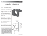
4. SPECIFICATIONS
48.09"
(1221.6 mm)
2.34"
(59.4mm)
52.25"
(1327.2 mm)
40.00"DIA.
(1016.0 mm)
Rotating Parts
8.57"
(217.8 mm) 107.34"
(2726.5 mm)
64.00"
(1625.6 mm)
Figure: 1. Model PFM1632 Pipemaster
Weight (Approx.): 5200 lbs (2,358.7 kg)
Available Feed Travel: 5.50"(139.7mm)
Clearance and Dimensions
Maximum Rotating Head DIA: 40.00"(1016mm)
Length (parallel to axis of pipe): 107.34"(2726.5mm)
Cutting Capacities
Basic Pipe Sizes: Mostschedulesof16"through32"pipe.
Basic Tube Sizes
Upto1.88"(47.8mm)walltubingwithamaximumODof32.00"(812.8mm)anda
minimumIDof13.90"(353.1mm)maybebeveledwiththeStandardMandrel.
Model PFM1632 PIPEMASTER™
92-1456 Rev. 230201 9

Wall Thickness Capacity
Wallthicknessofstandardpipescheduleswithwallthicknessesupto1.88"(47.8mm)in
the range listed. Tubing or pipe with greater wall thickness may be handled provided the ID
isequalorgreaterthan13.90"(353.1mm)andtheODisequalorlessthan32.00"(812.8
mm). Contact Tri Tool Inc. for procedures to use with heavier walled tubing or pipe.
Material Cutting Capabilities
Mild steels, chrome steels (Rc 35 max), API X42 through X85, stainless steel, copper-nickel
alloys,andaluminumwithoutlimitationsexceptsizeandwallthicknessasspeciedinthe
previous paragraphs.
Inconel and other high temperature alloys may require special procedures as a function of
wall thickness and type of end preparations. Contact Tri Tool’s Engineering Department for
details.
Cutting Head Speeds
Dual Hydraulic Drive: Maximum Cutting Head Speed 42 RPM
Feed
DualHydraulicPoweredCylinderswithfastfeedcontrolinbothdirectionsandne
adjustment feed for cutting.
Mounting
Hydraulically actuated cylinder expands Mandrel Pins and Jaw Blocks.
Drive System
DualHydraulicDriveMotorfor16"(406.4mm)to32"(812.8mm)pipe.
Requires separate Hydraulic power supply. Ref: HPU 75-60/5 Unit.
Power Requirement
60 GPM @ 2000 PSI Warranty (Limited)
5 GPM @ 2000 PSI Warranty (Limited)
TRI TOOL INC.
92-1456 Rev. 23020110

WARRANTY (LIMITED)
Parts and/or equipment are warranted against defects in material and workmanship for one
year from date of purchase. Full details supplied on
request and/or with tools.
Spare parts and Standard Tool Bit Inserts and Holders are available from stock.
Engineeringdesignservicesforcustomtoolsandspecialfunctionmodicationsare
available from the factory.
All Tri Tool and Allied Equipment Products are subject to design improvements and
specicationchangesatanytimewithnoobligationtounitsalreadysold.
Model PFM1632 PIPEMASTER™
92-1456 Rev. 230201 11

This Page is Intentionally Left Blank

Model PFM 1632 PIPEMASTER®
92-1456 Rev. 230201 13
5. HYDRAULIC SCHEMATIC
G4
DRIVE RAPID
FEED
FEED
CLAMP
JOG
60 GPM PUMP
TRI TOOL INC
HPU 70-60/5
(75 HP Motor w/
Tandem Pumps)
5 GPM PUMP
Return Reservoir
P
G5
T
DRIVE
PRESSURE
G3
CLAMP
PRESSURE
DVP
A2
B2
G2
DVA
B3
DVB
A3
P
A
T
B
FEED
CYLINDERS
B1
A1
CLAMP
CYLINDER
DRIVE
MOTORS
P B A
CAGE
SAFETY VALVE
IN
OUT
G1
PCV1
PCV2 PCV3 PCV4 PCV5 PCV6
CV3
PCV7
CV2
CV1CV5CV4
PSV1
TRI TOOL INC
D-30995
Figure: 3. Hydraulic Schematic

This Page is Intentionally Left Blank

6. OPERATION
ADJUSTMENTS
TOOL HOLDER HEIGHT ADJUSTMENT
4. Loosen the Tool Holder
retaining shoulder screw.
2. Rotate tracking wheel until
it is at it’s highest outward
point.
1. Loosen the tracking
wheel shoulder screw.
3. Loosen the 2 cap
screws of the tool
holder retaining bar.
Thismeasurementshouldbe.250"higherthanthe
radiusoftheIDofthepipeminus3.875"
5. Slide the tool holder
to bring it to the
measured height, if
between gear rack
teeth, go to the next
higher tooth.
6. Set all other tool
holders at the same
height and tighten all
screws.
Model PFM1632 PIPEMASTER™
92-1456 Rev. 230201 15

1. Before any adjustment can be made, all
hex screws must be loosened and the
inside cup brush must be loosened.
2. Rotate axial adjustment screw clockwise
until it stops.
3. Push the tool bit holder until it bottoms in
the tool slot and tighten all hex screws.
Measure height for step 'B'.
6. Use a feeler gauge to
measure gap between tool
bit and tracking wheel to
adjust the land thickness
of the prep.
4. Loosen the
tracking wheel
shoulder bolt.
5. Rotate tracking
wheel eccentric
shaft to adjust the
land thickness.
7. Tighten the tracking
wheel shoulder bolt.
8. Reset and tighten cup brush.
STEP ‘A’ - ADJUSTING RADIUS TOOL HOLDER ASSEMBLY
B
TRI TOOL INC.
92-1456 Rev. 23020116

STEP ‘B’ - ADJUSTING THE INNER BEVEL TOOL HOLDER ASSEMBLY
1. Before any adjustment can be
made, all hex screws must be
loosened and the inside cup brush
must be loosened.
2. Rotate axial adjustment screw to
adjust tool holder height and after
adjustment is done tighten all hex
screws.
7. Take this measurement for Step 'C'.
3. Adjust this height to match
measurement
taken in step 'A'.
5. Use a feeler gauge
to adjust this
height. (Add the
land thickness to
the radius of the 'J'
bevel minus the
radius of the
insert.) .Rotate
tracking wheel to
adjust accordingly.
Example:
radius + land
thickness – insert
3.2 mm + 1.2 mm
– 2.3 = 2.1 mm
4. Loosen the tracking
wheel shoulder screw.
6. Tighten the tracking wheel shoulder
screw.
7. Reset and tighten the cup brush.
Model PFM1632 PIPEMASTER™
92-1456 Rev. 230201 17

STEP ‘C’ - ADJUSTING THE OUTER BEVEL TOOL HOLDER ASSEMBLY
1. Before any adjustment can be made, all
hex screws must be loosened and the
inside cup brush must be loosened.
2. Rotate axial adjustment screw to adjust
tool holder height and after adjustment is
done tighten all hex screws.
3. Adjust this height to match measurement
taken in
step 'B'.
4. Loosen the tracking
wheel shoulder screw.
5. Rotate the tracking
wheel cam to adjust
tool bit radial height
to split the chip load
equally between the
2 bevel bits.
6. Tighten the
tracking wheel
shoulder screw.
7. Reset and tighten the
cup brush.
Pipe
(Ref. Only)
#3
STEP ‘C’ - ADJUSTING THE OUTER BEVEL TOOL HOLDER ASSEMBLY
Pipe
(Ref. Only)
#3
STEP ‘C’ - ADJUSTING THE OUTER BEVEL TOOL HOLDER ASSEMBLY
TRI TOOL INC.
92-1456 Rev. 23020118
/