Extech Instruments MN10 User manual

Category
Multimeters
Type
User manual

Extech Instruments MN10 is a versatile multimeter that measures AC/DC voltage, DC current, resistance, performs diode and battery tests, and features a non-contact voltage detector for convenient and safe electrical work. With its rugged design for heavy-duty use, this meter is a reliable tool for various applications, including electrical troubleshooting, automotive diagnostics, and more.

Extech Instruments MN10 is a versatile multimeter that measures AC/DC voltage, DC current, resistance, performs diode and battery tests, and features a non-contact voltage detector for convenient and safe electrical work. With its rugged design for heavy-duty use, this meter is a reliable tool for various applications, including electrical troubleshooting, automotive diagnostics, and more.

User's Guide
Pocket MultiMeter
Model MN10
MN10-en-GB_V1.3 09/16
2
Introduction
Congratulations on your purchase of the Extech MN10 Pocket Multimeter. This meter measures
AC/DC Voltage, DC Current, Resistance, Diode Test, and Battery test. It features a rugged design for
heavy duty use This meter is shipped fully tested and calibrated and, with proper use, will provide
years of reliable service.
Safety
This symbol adjacent to another symbol, terminal or operating device indicates
that the operator must refer to an explanation in the Operating Instructions to
avoid personal injury or damage to the meter.
This WARNING symbol indicates a potentially hazardous situation, which if not
avoided, could result in death or serious injury.
This CAUTION symbol indicates a potentially hazardous situation, which if not
avoided, may result damage to the product.
This symbol advises the user that the terminal(s) so marked must not be
connected to a circuit point at which the voltage with respect to earth ground
exceeds 500 VAC or VDC.
This symbol adjacent to one or more terminals identifies them as being associated
with ranges that may, in normal use, be subjected to particularly hazardous
voltages. For maximum safety, the meter and its test leads should not be handled
when these terminals are energized.
This symbol indicates that a device is protected throughout by double insulation or
reinforced insulation.
WARNING
CAUTION
MAX
500V
MN10-en-GB_V1.3 09/16
3
SAFETY INSTRUCTIONS
This meter has been designed for safe use, but must be operated with caution. The rules listed below
must be carefully followed for safe operation.
1. NEVER apply voltage or current to the meter that exceeds the specified maximum:
Input Protection Limits
Function Maximum Input
V DC or V AC 500VDC/AC
mA AC/DC 200mA AC/DC
Resistance, Diode Test 500VDC/AC
2. USE EXTREME CAUTION when working with high voltages.
3. DO NOT measure voltage if the voltage on the "COM" input jack exceeds 500V above earth
ground.
4. NEVER connect the meter leads across a voltage source while the function switch is in the
current, resistance, or diode mode. Doing so can damage the meter.
5. ALWAYS discharge filter capacitors in power supplies and disconnect the power when making
resistance or diode tests.
6. ALWAYS turn off the power and disconnect the test leads before opening the covers to replace
the fuse or batteries.
7. NEVER operate the meter unless the back cover and the battery and fuse covers are in place
and fastened securely.
8. If the equipment is used in a manner not specified by the manufacturer, the protection provided
by the equipment may be impaired.
Controls and Jacks
1. NCV indicator lamp
2. LCD Display
3. Power button
4. Function switch
5. COM jack
6. Data Hold button
7. Battery compartment (rear)
8. Positive jack
Symbols and Annunciators
Diode test Ohms
Low Battery V Volts
µ micro A Amps
m milli AC Alternating current
A Amps DC Direct current
k kilo
MN10-en-GB_V1.3 09/16
4
Operating Instructions
WARNING: Risk of electrocution. High-voltage circuits, both AC and DC, are very dangerous and
should be measured with great care.
1. ALWAYS switch the meter OFF when the meter is not in use using the power on/off button.
2. If “1” appears in the display during a measurement, the value exceeds the range you have
selected. Change to a higher range.
NOTE: On some low AC and DC voltage ranges, with the test leads not connected to a device, the
display may show a random, changing reading. This is normal and is caused by the high-input
sensitivity. The reading will stabilize and give a proper measurement when connected to a circuit.
NON-CONTACT VOLTAGE (NCV)
The meter can detect the presence of AC voltage (from 100 to 600VAC) simply by being held very
near to a voltage source.
WARNING: Test the AC voltage detector on a known live circuit before each use.
WARNING: Before using the meter in the AC Voltage Detector mode, verify that the battery is fresh
by confirming characters appear on the LCD when the function dial is turned to any position. Do
not attempt to use the meter as an AC Voltage Detector if the battery is weak or bad.
The NCV function works on any rotary switch position.
1. Turn the meter on.
2. The NCV function works with the meter’s function switch set to any position.
3. Be sure to test the NCV function on a known live circuit before use.
4. Hold the top of the meter very close to the voltage source.
5. If voltage is present, the red LED indicator directly above the meter’s LCD display
will solidly illuminate.
DC VOLTAGE MEASUREMENTS
CAUTION: Do not measure DC voltages if a motor on the circuit is being switched ON/OFF.
Large voltage surges may occur that can damage meter.
1. Set the function switch to the highest V DC position.
2. Insert the black test lead banana plug into the negative (COM) jack.
Insert the red test lead banana plug into the positive (V) jack.
3. Touch the black test probe tip to the negative side of the circuit.
Touch the red test probe tip to the positive side of the circuit.
4. Read the voltage in the display. Reset the function switch to successively lower V
DC positions to obtain a higher resolution reading. The display will indicate the
proper decimal point and value. If the polarity is reversed, the display will show (-)
minus before the value.
MN10-en-GB_V1.3 09/16
5
AC VOLTAGE MEASUREMENTS
WARNING: Risk of Electrocution. The probe tips may not be long enough to contact the live parts
inside some 240V outlets for appliances because the contacts are recessed deep in the outlets. As
a result, the reading may show 0 volts when the outlet actually has voltage on it. Make sure the
probe tips are touching the metal contacts inside the outlet before assuming that no voltage is
present.
CAUTION: Do not measure AC voltages if a motor on the circuit is being switched ON or OFF.
Large voltage surges may occur that can damage the meter.
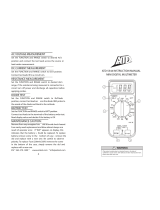
1. Set the function switch to the highest V AC position.
2. Insert the black test lead banana plug into the negative (COM) jack.
Insert red test lead banana plug into the positive (V) jack.
3. Touch the black test probe tip to the negative side of the circuit.
Touch the red test probe tip to the positive side of the circuit.
4. Read the voltage in the display. Reset the function switch to successively lower V
AC positions to obtain a higher resolution reading. The display will indicate the
proper decimal point and value.
DC CURRENT MEASUREMENTS
1. Insert the black test lead banana plug into the negative (COM) jack.
2. Set the function switch to the 200mA or 2000A DC range position.
3. Insert the red test lead banana plug into the mA jack.
4. Remove power from the circuit under test, then open up the circuit at the point
where you wish to measure current.
5. Touch the black test probe tip to the negative side of the circuit.
Touch the red test probe tip to the positive side of the circuit.
6. Apply power to the circuit.
7. Read the current in the display. The display will indicate the proper decimal point
and value.
RESISTANCE MEASUREMENTS
WARNING: To avoid electric shock, disconnect power to the unit under test and discharge all
capacitors before taking any resistance measurements. Remove the batteries and unplug the line
cords.
1. Set the function switch to the highest position.
2. Insert the black test lead banana plug into the negative (COM) jack
Insert the red test lead banana plug into the positive  jack.
3. Touch the test probe tips across the circuit or part under test. It is best to
disconnect one side of the part under test so the rest of the circuit will not
interfere with the resistance reading.
4. Read the resistance in the display and then set the function switch to the lowest
position that is greater than the actual or any anticipated resistance. The
display will indicate the proper decimal point and value.
MN10-en-GB_V1.3 09/16
6
DIODE CHECK
.
1. Set the function switch to the position
2. Insert the black lead banana plug into the negative (COM) jack
Insert the red test lead banana plug into the positive () jack.
3. Connect the red test lead to the anode of the diode and the black lead to the
cathode.
4. The forward voltage drop in mV will be displayed. If the leads are reversed, the
display will indicate “I”.
BATTERY TEST
1. Insert the black test lead banana plug into the negative COM jack and the red test lead banana
plug into the positive V jack.
2. Select the 9V BAT position using the function switch.
3. Connect the red test lead to the positive side of the 9V battery and the black test lead to the
negative side of the 9V battery.
4. Read the voltage in the display (> 8.2V indicates good; < 7.2 indicates a bad; 7.2V to 8.2V
indicates a weak)
MN10-en-GB_V1.3 09/16
7
Maintenance
This MultiMeter is designed to provide years of dependable service, if the following care instructions
are performed:
1. KEEP THE METER DRY. If it gets wet, wipe it off.
1. USE AND STORE THE METER IN NORMAL TEMPERATURES. Temperature extremes can
shorten the life of the electronic parts and distort or melt plastic parts.
2. HANDLE THE METER GENTLY AND CAREFULLY. Dropping it can damage the electronic parts
or the case.
3. KEEP THE METER CLEAN. Wipe the case occasionally with a damp cloth. DO NOT use
chemicals, cleaning solvents, or detergents.
4. USE ONLY FRESH BATTERIES OF THE RECOMMENDED SIZE AND TYPE. Remove old or
weak batteries so they do not leak and damage the unit.
5. IF THE METER IS TO BE STORED FOR A LONG PERIOD OF TIME, the batteries should be
removed to prevent damage to the unit.
BATTERY REPLACEMENT
WARNING: To avoid electric shock, disconnect the test leads from any source of voltage before
removing the back cover or the battery cover.
1. Disconnect the test leads from the meter.
2. Remove the Phillips head screw located on the back of the instrument and remove the battery
cover.
3. Replace the 12V battery.
4. Secure the fuse/battery compartment cover.
5. Dispose of the old battery as required by local regulations.
The end user is legally bound (EU Battery ordinance) to return all used batteries, disposal
in the household garbage is prohibited! Bring used batteries / accumulators to collection
points in your community or wherever batteries / accumulators are sold!
Disposal: Follow the valid legal stipulations in respect of the disposal of the device at the
end of its lifecycle
WARNING: To avoid electric shock, do not operate your meter until the battery cover is in place and
fastened securely.
FUSE REPLACEMENT
1. Disconnect the test leads from the meter.
2. Remove the 3 Phillips head screws securing the meter’s rear cover and lift the cover off.
3. Gently remove the fuse and install the new fuse into the holder.
4. Always use fuses of the proper size and value 0.2A/250V fast blow
5. Secure the rear cover.
WARNING: To avoid electric shock, do not operate your meter until the rear cover is in place and
fastened securely.
MN10-en-GB_V1.3 09/16
8
Specifications
Function Range Resolution Accuracy (reading)
DC Voltage
(V DC)
200mV 0.1mV
(0.5% rdg + 2d)
2000mV 1mV
20V 0.01V
200V 0.1V
500V 1V
AC Voltage
(V AC) (50/60Hz)
200V 0.1V
(1.2% rdg + 10d
500V 1V
DC Current
(A DC)
2000
A 1
A
(1.2% rdg + 2d)
200mA
100
A
(1.5% rdg + 2d)
Resistance
200
0.1
(0.8% rdg + 4d)
2000
1
20k
0.01k
200k
0.1k
2000k
1k
(1.5% rdg + 2d)
Battery Test 9V 10mV
(1.2% rdg + 2d)
NOTE: Accuracy specs consist of two elements:
(% reading): Accuracy of measurement circuit.
(+ digits): Accuracy of analog to digital converter.
NOTE: Accuracy is stated at 65
o
F to 83
o
F (18
o
C to 28
o
C) and < 75% RH.
Diode Test Test current of 1mA maximum, open circuit voltage 2.8V DC typical
Battery Test current 9V (6mA)
Input Impedance 1M
ACV Bandwidth 50Hz to 60Hz
DCA voltage drop 200mV
Display 3 ½ digit, 2000 count LCD
Over-range “1” is displayed
Polarity Automatic (no indication for positive polarity); Minus (-) sign for negative
polarity.
Measurement Rate 2 times per second, nominal
Low Battery is displayed
Battery One 12V (VA23A, MS21) battery
Fuse mA, µA ranges; 0.2A/250V fast blow
Operating Temp. 32ºF to 122ºF (0ºC to 50ºC)
Storage Temp. -4
o
F to 140
o
F (-10
o
C to 60
o
C)
Operating Humidity < 70%
Storage Humidity < 80%
Operating Altitude 7000ft. (2000) meters maximum.
Weight 3.6 oz. (102g)
Size 4.3” x 2.1” x 1.3” (108mm x 53mm x 32mm)
Safety For indoor use and in accordance with Overvoltage Category II, Pollution
Degree 2. Category II includes local level, appliance, portable equipment,
etc., with transient overvoltages less than Overvoltage Category III.
Copyright©20122016FLIRSystems,Inc.
Allrightsreservedincludingtherightofreproductioninwholeorinpartinanyform
www.extech.com
  • Page 1 1
  • Page 2 2
  • Page 3 3
  • Page 4 4
  • Page 5 5
  • Page 6 6
  • Page 7 7
  • Page 8 8

Extech Instruments MN10 User manual

Category
Multimeters
Type
User manual

Extech Instruments MN10 is a versatile multimeter that measures AC/DC voltage, DC current, resistance, performs diode and battery tests, and features a non-contact voltage detector for convenient and safe electrical work. With its rugged design for heavy-duty use, this meter is a reliable tool for various applications, including electrical troubleshooting, automotive diagnostics, and more.

Ask a question and I''ll find the answer in the document

Finding information in a document is now easier with AI