Page is loading ...

CONTENTS
1. INTRODUCTION .............................................…….........
1
2. SAFTY INSTRUCTION...................……...………….…....
2
3. CABLE CONNECTION..........................……..……..….....
4
4. SYSTEM DESCRIPTION.............……........…….......…...
5
5. INVERTER OPERATION ................................................
11
6. TROUBLE SHOOTING GUIDE.......................….….....…
16
7. OPERATION MODES OF THE INVERTER ...……..........
18
8. SPECIFICATION OF INVERTER....................................
20
9. NEW LCD SETTINGS.................................... .................
24

1
1. INTRODUCTION
1.1 General Description
The pure sine wave Inverter, a powerful all-in-one solution, delivers
unsurpassed clean true sine wave output power and combines this with a
selectable multistage battery charging current. Applicable for any kind of
loads, such as air conditioner, home appliances, consumer electronic and
office equipments. This series features a durable & continuous 24 operation.
The built-in 5-stage intelligent charger automatically charges any type of
batteries without the risk of overcharge. The compact & modular design
makes utility interactive installations easier and more cost effective. It is a
high quality product that offers the best price/performance ratio in the
industry.
1.2 Key features
1. Multiple microprocessor design base.
2. Compatible with both linear & non-linear load.
3. Stronger charger to support batteries of 600AH up.
4. 24 hours operation on the inverter.
5. DC start and automatic self-diagnostic function.
6. THD less than 3%.
7. High efficiency design to save electricity.
8. Low heat dissipation in long time operation
9. Design to operate under harsh environment
10 3U 19” Rack Mount or WALL Mounted design
1.3 Important Notices
1. Read instructions carefully before operating the Inverter.
2. INVERTER power connect instruction should be followed.
3. Please don‘t open the case to prevent danger.
5. Retain the load within the rating of INVERTER to prevent faults.
6. Keep the INVERTER clean and dry.

2
2. SAFTY INSTRUCTION
2.1 Transporting
1. Disconnect all power cables if necessary.
2. Be careful not to damage the INVERTER while transporting.
3. Don‘t move the INVERTER upside down.
4. Please transport the INVERTER system only in the original packaging (to
protect against shock and impact).
2.2 Positioning
1. Do not put the INVERTER on rugged or declined surface.
2. Do not install the INVERTER system near water or in damp environments.
3. Do not install the INVERTER system where it would be exposed to direct
sunlight or near heat.
4. Do not block off ventilation openings in the INVERTER system’s housing
and don’t leave objects on the top of the INVERTER.
5. Keep the INVERTER far away from heat emitting sources.
6. Do not expose it to corrosive gas.
7. Ambient temperature : 0℃ - 40℃
2.3 Installation
1. Connect the INVERTER system only to an earthed shockproof socket
outlet.
2. Place cables in such a way that no one can step on or trip over them.

3
2.4 Operation
1. Do not disconnect the mains cable on the INVERTER system or the
building wiring socket outlet during operations since this would cancel the
protective earthing of the INVERTER system and of all connected loads.
2. The INVERTER can be started up by only DC power source (or batteries).
The output terminals may be live even when the INVERTER is not connected
to the AC supply.
3. Ensure that no fluids or other foreign objects can enter the INVERTER
system.
2.5 Maintenance and Service
1. Caution - risk of electric shock.
Even after the unit is disconnected from the mains power supply (building
wiring socket outlet), components inside the INVERTER system are still
connected to the battery and are still electrically live and dangerous. Before
carrying out any kind of servicing and/or maintenance, disconnect the
batteries and verify that no current is present.
2. Batteries may cause electric shock and have a high short-circuit current.
Please take the precautionary measures specified below and any other
measures necessary when working with batteries:
- remove wristwatches, rings and other metal objects
- use only tools with insulated grips and handles.

4
3. CABLE CONNECTION
3.1 Inspection
1. The system may be installed and wired only by qualified electricians in
accordance with applicable safety regulations.
2. When installing the electrical wiring, please note the nominal amperage of
your incoming feeder.
3. Inspect the packaging carton and its contents for damage. Please inform
the transport agency immediately should you find signs of damage.
Please keep the packaging in a safe place for future use.
4. Please ensure that the incoming feeder is isolated and secured to prevent
it from being switched back on again.
3.2 Connection
The INVERTER is connected with terminal blocks to AC main and the
loads, please use a proper rating of the power cord.

5
4. SYSTEM DESCRIPTION
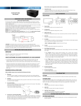
4.1 Front Panel Description for LCD Model
1. LCD Display: This indicates the INVERTER operation information,
including INVERTER status, input/output voltage, input/output frequency,
battery voltage, battery capacity left, output load, inside temperature, and
the times of history events.
2. Up-key: Use to select upward the INVERTER status on LCD Display.
3. Down-key: Use to select downward the INVERTER status on LCD Display.
Beside, press it simultaneously with the Up-key to switch off the
INVERTER.
4. Enter-Key: It is pressed with the Down-key to turn on the INVERTER. In
battery operation mode, press it with Up-key at the same time to disable
the buzzer. Beside, it is pressed to confirm and enter the item selected.
5. Fault LED (red): To indicate the INVERTER is in fault condition because of
inverter shutdown or over-temperature.

6
6. Warning LED (yellow): To indicate the INVERTER is in the status of
overload, bypass and battery back-up.
7. Normal LED (green): To indicate the INVERTER is operating normally.
8. ON/TEST/MUTE key: It should be pressed with the control key
simultaneously to switch on INVERTER, do INVERTER auto-test in
normal AC mode and turn off the buzzer in battery operation.
4.2 Outline Description
1.2KVA Rack Mount Type

7
2.4KVA / 3.6KVA Rack Mount Type

8
1.2KVA Wall Mounted Type

9
2.4KVA / 3.6KVA Wall Mounted Type

10
5KVA / 6KVA / 8KVA Wall Mounted Type

11
5. INVERTER OPERATION
5.1 Check Prior to Start Up
1. Ensure the INVERTER is in a suitable positioning.
2. Check input cord is secured.
3. Make sure the load is disconnected or in the “OFF” position.
4. Check if input voltage meets the INVERTER rating required.
5.2 Storage Instruction
Disconnect input power in rear panel if you will not use it for long period. If the
INVERTER is stored over 3 months, please keep supplying power to the
INVERTER for at least 24 hours to ensure battery fully recharged.
5.3 Operation Procedure for LCD Model
Please follow the instructions below for INVERTER operation.
1. Once the AC source is connected,
the LCD Display shall light up
immediately (8~10 seconds in main
menu of greeting context) to standby
for INVERTER startup.
2. By pressing the Enter-key and the Down-key simultaneously for 3 seconds,
the INVERTER will start up after two beeps and Normal LED lights up to
indicate the power is from its bypass AC main to the load.
3. When the Down-key and the Up-key are pressed simultaneously for 3
seconds, the INVERTER will be turned off after two beeps.

12
4. LCD Display Menu
Use Up/Down key to select menu-displays of the LCD described below.
This screen will refresh once the system power is enabled.
Rated Spec
Status
Voltage
Frequency

13
Battery Status
Output Power
Temperature
History Record

14
5. Input Voltage Range Setting
After INVERTER startup, press the Down-key to find the screen and then
press Enter-key for setting.
Input Voltage Adjust
A. In this screen, press Enter-key to
enter the following steps for input
voltage and frequency adjustment.
B. The cursor (→) will pop up to
indicate the input voltage and
frequency newly selected.
C. Use Up or Down-key to adjust the
input LOW voltage (if 220V
configure, 120V~200V is selectable;
if 110V configure, 60V~100V is
selectable). Press Enter-key to
confirm voltage and then the cursor
will move to input HIGH voltage
selection (if 220V configure,
250V~280V is selectable; if 110V
configure, 125V~140V is
selectable).
D. Once the correct voltage is
selected, press Enter-key again to
save the selection.

15
6. Output Voltage / Frequency Setting
Output Voltage & Frequency Adjust
A. In this screen, press Enter-key to
enter the following steps for output
voltage and frequency adjustment.
B. The cursor (→) will pop up to
indicate the output voltage and
frequency newly selected.
C. Use Up or Down-key to adjust the
output voltage (if 220V configure,
220V, 230V, and 240V is
selectable; if 110V configure, 100,
110V, 115V, and 120V is
selectable). Press Enter-key to
confirm voltage and then the cursor
will move to frequency selection.
The output frequency (50Hz or
60Hz) can be adjusted by the same
key operation.
D. Once the correct voltage is
selected, press Enter-key again to
save the selection.

16
7. AC/DC Prior Setting (Option) Functioning only under AC (Line) Mode .
AC/DC Prior Adjust
A. In this screen, press Enter-key to
enter the following steps for AC/DC
prior adjustment.
B. The cursor (→) will pop up to
indicate the AC/DC prior.
C. Use Up or Down-key to adjust
AC/DC prior.
D. Press Enter-key again to save the
selection.
E. Turn off the unit and then restart it
to enable the setting

17
8. Green Power On/Off & Load & Time Setting (Option) Functioning only
under INVERTER Mode.
Green Power On/Off & Load & Time Adjust
A. In this screen, press Enter-key
twice to enter the following steps for
Green Power On/Off adjustment.
B. The cursor (→) will pop up to
indicate the Green Power On/Off.
C. Use Up or Down-key to select the
Green Power On/Off. Press
Enter-key to confirm, and then the
cursor will move to the time
adjustment. The time period
(15Sec., 30Sec., 45Sec., and
60Sec. is selectable) for next
detecting can be adjusted by the
same key operation.
D. Press Enter-key again to save the
selection.

18
9. Battery Shutdown Voltage & Current Setting (48V/ 24V)
Battery Shutdown Voltage & Current
Adjust
A. In this screen, press Enter-key to
enter the following steps for
battery shutdown voltage
adjustment.
B. The cursor (→) will pop up to
indicate the battery shutdown
voltage.
C. Use Up or Down-key to adjust the
battery shutdown voltage (if 48V
configure, HIGH: 42V, MIDDLE:
40V, LOW: 38V is selectable; if
24V configure, HIGH: 21V,
MIDDLE: 20V, LOW: 19V is
selectable).
D. Once the correct voltage is
selected, press Enter-key again
to save the selection.

19
10. Battery Charging Current Setting
Battery Charging Current Adjust
A. In this screen, press Enter-key
twice to enter the following
steps for battery charging
current adjustment.
B. The cursor (→) will pop up to
indicate the battery charging
current.
C. Use Up or Down-key to adjust
the battery charging current
(LOW: 100AH, MIDDLE:
300AH, HIGH: 600AH is
selectable).
D. Once the correct battery
charging current is selected,
press Enter-key again to save
the selection.
/