Page is loading ...

KVS Series Power Amplifier
Obtaining Other Language Versions: To obtain information in another language about the use of this product, please
contact your local Crown Distributor. If you need assistance locating your local distributor, please contact Crown at 574-294-8000.
This manual does not include all of the details of design, production, or variations of the equipment. Nor does it cover every possi-
ble situation which may arise during installation, operation or maintenance.
The information provided in this manual was deemed accurate as of the publication date. However, updates to this information may
have occurred. To obtain the latest version of this manual, please visit the Crown website at www.crownaudio.com.
Trademark Notice: Crown, Crown Audio, and Amcron are registered trademarks of Crown International. Other trademarks are
the property of their respective owners.
Later versions of this manual and additional information about this product may be available at the Crown website at www.crownau-
dio.com.
Some models may be exported under the name Amcron®
©2015 by Harman International, 1718 W. Mishawaka Rd., Elkhart, Indiana 46517-9439 U.S.A. Telephone: 574-294-8000.
Crown
574-294-8000Crown
Crownwww.crownaudio.com
Crownwww.crownaudio.com
CrownCrown AudioAmcronHarman International
©2015 Harman International1718 W. Mishawaka Rd., Elkhart, Indiana 46517-9439 U.S.A.
574-294-8000
Operation Manual
操作手册
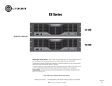
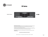
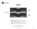
KVS
KVS300
KVS500
KVS700
KVS1000
5044907 01/15

KVS Series Power Amplifier KVS
2
Operation Manual
Important Safety Instructions .................................................3
1. Welcome ......................................................................4
2. Setup ..........................................................................5
2.1 Unpacking ................................................................................................................. 5
2.3 Ensure Proper Cooling ..............................................................................................6
2.2 Installing the amplifier ..............................................................................................6
3. Front Panel ...................................................................7
4. Back Panel ....................................................................8
5. Wiring .........................................................................9
5.1 Stereo (Dual) Wiring Using the Speakon
®
Connectors 1 ...........................................9
5.2 Stereo (Dual) Wiring Using the Speakon
®
Connectors 2 ...........................................9
5.3 Stereo (Dual) Wiring Using the Binding Post Connectors .......................................10
5.4 Bridge Wiring Using the Speakon
®
Connectors ......................................................10
5.5 Bridge Wiring Using the Binding Post Connectors .................................................. 11
5.6 Parallel Wiring Using the Speakon
®
Connectors .....................................................11
5.7 Parallel Wiring Using the Binding Post Connectors ................................................12
6. Specification ............................................................... 13
7. Warranty ................................................................... 14
...................................................................3
1. ...........................................................................4
2. ...........................................................................5
2.1 ......................................................................................................................................... 5
2.2 ................................................................................................................................ 6
2.3 ....................................................................................................................... 6
3. ........................................................................7
4. ........................................................................8
5. ........................................................................ 9
5.1 Speakon
®
1 ........................................... 9
5.2 Speakon
®
2 ........................................... 9
5.3 ...........................................................10
5.4 Speakon
®
...................................................................... 10
5.5 ......................................................................................11
5.6 Speakon
®
............................................................................... 11
5.7 ...............................................................................................12
6. ......................................................................... 13
7. ......................................................................... 14
Content

KVS KVS Series Power Amplifier
3
Operation Manual
1. Read these instructions.
2. Keep these instructions.
3. Heed all warnings.
4. Follow all instructions.
5. Do not use this apparatus near water.
6. Clean only with a dry cloth.
7. Do not block any ventilation openings. Install
in accordance with the manufacturer’s
instructions.
8. Do not install near any heat sources such
as radiators, heat registers, stoves, or other
apparatus (including amplifiers) that produce
heat.
9. Do not defeat the safety purpose of the po-
larized or grounding-type plug. A polarized
plug has two blades with one wider than the
other. A grounding-type plug has two blades
and a third grounding prong. The wide blade
or the third prong is provided for your safety.
If the provided plug does not fit into your
outlet, consult an electrician for replacement
of the obsolete outlet.
10 . Protect the power cord from being walked
on or pinched, particularly at plugs, con-
venience receptacles, and the point where
they exit from the apparatus.
11. Only use attachments/accessories specified
by the manufacturer.
12. Use only with a cart, stand, tripod, bracket,
or table specified by the manufacturer, or
sold with the apparatus. When a cart is
used, use caution when moving the cart/
apparatus combination to avoid injury from
tip-over.
13. Unplug this apparatus during lightning
storms or when unused for long periods of
time.
14. Refer all servicing to qualified service
personnel. Servicing is required when the
apparatus has been damaged in any way,
such as powersupply cord or plug is dam-
aged, liquid has been spilled or objects have
fallen into the apparatus, the apparatus has
been exposed to rain or moisture, does not
operate normally, or has been dropped.
15. Use the mains plug to disconnect the appa-
ratus from the mains.
16. Warning: to reduce the risk of fire
or electric shock, do not expose
this apparatus to rain or moisture.
17. Do not expose this equipment to dripping or
splashing and ensure that no objects filled
with liquids, such as vases, are placed on
the equipment.
18. The mains plug of the power supply cord
shall remain readily operable.
TO PREVENT ELECTRIC SHOCK DO NOT
REMOVE TOP OR BOTTOM COVERS.
NO USER SERVICEABLE PARTS INSIDE.
REFER SERVICING TO QUALIFIED SERVICE
PERSONNEL.
TO COMPLETELY DISCONNECT THIS
EQUIPMENT FROM THE AC MAINS,
DISCONNECT THE POWER SUPPLY
CORD PLUG FROM THE AC RECEPTA-
CLE. THE MAINS PLUG OF THE POWER
SUPPLY CORD SHALL REMAIN READILY
OPERABLE.
WATCH FOR THESE SYMBOLS:
Warning: The lightning bolt triangle is
used to alert the user to the risk of electric
shock.
Cauotion: The exclamation point triangle is
used to alert the user to important operat-
ing or maintenance instructions.
This device is designed and evaluated
under the condition of 2000 meters tall
above sea level; and, it can be only used
in locations below 2000 meters tall above
sea level. Using the device above 2000
meters altitude would result in high safety
risk.
The device is designed and evaluated
under the condition of non-tropical cli-
mate; and, it can be only used in locations
in non-tropical climate areas. Using the
device in tropical climate areas would
result in high safety risk.
1.
2.
3.
4.
5.
6.
7.
8.
9.
10.
11.
12.
13.
14.
15.
16.
17.
18.
19.
注意这些符号
警告:
注意:
2000m
2000m 2000m
IEC60065-2001
GB8898-2011
EMC
GB13837-2012
GB17625.1-2012
16A
≤2000
m
≤2000
m
Important Safety Instructions

KVS Series Power Amplifier KVS
4
Operation Manual
1.
KVS CROWN
KVS
•
• 2U
•
• XLR Speakon
®
• 6 LED
Crown Amplifier Application Guide
www
.
crownaudio
.
com Crown
1. Welcome
The KVS Series of power amplifiers from Crown represent a new era in affordable, quality power amplification. The line
consists of four models in a uniform, rugged chassis, incorporating the best of reliable design principles and innovative
features.
Modern power amplifiers are sophisticated pieces of engineering products, which are capable of producing extremely high
power. If we need to have them providing years of reliable service, we must treat them seriously and have them correctly
installed.
In addition, KVS Series amplifiers include a number of features which require some explanation before they can be used to
their maximum advantage.
Please take time to study this manual so that you can obtain the best possible service from your amplifier.
Features:
• Simple, reliable design incorporates many popular features.
• Housed in a rugged, all-steel 2U chassis.
• Efficient forced-air fans prevent excessive thermal buildup.
• Electronically balanced XLR inputs. Touch-proof binding post and Speakon
®
outputs.
• Features precision detented level controls, power switch, power LED, and six LEDs which indicate signal, clip, and fault
for each channel.
How to Use This Manual
This manual provides you with the necessary information to safely and correctly setup and operate your amplifier. It does
not cover every aspect of installation, setup, or operation that might occur under every condition. For additional information,
please consult Crown’s Amplifier Application Guide (available at www.crownaudio.com), Crown Technical Support, your
system installer or retailer.
We strongly suggest you read all instructions, warnings and cautions contained in this manual. Also, for your protection,
please send in your warranty registration card today. And save your bill of sale - it's your official proof of purchase.

KVS KVS Series Power Amplifier
5
Operation Manual
2. Setup
2.
2.1 Unpacking
Please unpack and inspect your KVS amplifier for any damage that may have occurred during transit. If damage is found,
notify the transportation company immediately. Only you can initiate a claim for shipping damage, though Crown will
be happy to help as needed. If the product arrived showing signs of damage, save the shipping carton for the shipper’s
inspection.
We also recommend that you save all packing materials so you will have them if you ever need to transport the unit.
Never ship the unit without the factory carton and packing materials.
Package contains:
• One KVS amplifier;
• One Power Cord (compatible to retailer’s location);
• One operation manual (this manual);
• One product registration form (at the end of this manual);
• One warranty card (at the end of this manual);
• Rack mount brackets and screws.
For installation, you will need (not supplied):
• Input wiring cables
• Output wiring cables
• Rack for mounting amplifier (or a stable surface for stacking)
NOTE: Before you start to set up your amplifier, make sure you read and observe the Important
Safety Instructions found at the beginning of this manual.
2.1
Crown
• KVS
•
•
•
•
•
•
•
•

KVS Series Power Amplifier KVS
6
Operation Manual
2.3 Ensure Proper Cooling
When using an equipment rack, mount units directly on top of each other. Close any open spaces in rack with blank panels.
DO NOT block front or rear air vents. The side walls of the rack should be a minimum of two inches (5.1 cm) away from the
amplifier sides, and the back of the rack should be open.
CAUTION: Before you begin installing your amplifier, make sure it is disconnected from
the power source, with the power switch in the “off” position and all level controls turned
completely down (counterclock wise).
2.2
19 48.3
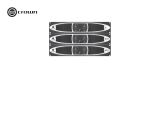
2.2 Installing the amplifier
NOTE: Before you begin, make sure your amplifier is disconnected from the power source,
with the power switch in the “off” position and all level controls turned completely down
(counterclockwise).
Use a standard 19-inch (48.3 cm) equipment rack. See above diagram for amplifier dimensions. You may also stack
amplifiers without using a cabinet.
NOTE: Amplifiers should be supported at both the front and rear of the rack. When stack the
amplifier with rack, flat plate or rails must be placed under amplifier to provide stable support.
Fault
Clip
Signal
POWER
KVS
POWER AMPLIFIER
12
12
0
0
10
10
0
0
10
10
19 in.
48.2 cm
3.5 in.
8.9 cm
15.6 in.
39.5 cm
2.
2. Setup (continued)
2.3
2 5.1cm

KVS KVS Series Power Amplifier
7
Operation Manual
3.
3. Front Panel
A
E F G H I
B C D
A.
B. / LED
LED
C. LED
LED
D.
E.
F. LED
LED
•
•
•
G.
H. LED
LED- 40 dBu
I.
A. Gain (Level) Controls:
Two black rotary level controls, one for each channel.
B. Clip/Thermal Indicator:
Two yellow LEDs, one for each channel, illuminate when
thermal compression begins due to excessive temperature
conditions or flash when audio distortion occurs.
C. Fault Indicator:
Two red LEDs, one for each channel, illuminate when
amplifier is in protect mode. Also illuminates briefly during
normal power-up when amplifier is first switched on.
D. Bracket:
Attached in the package with amplifier.
E. Installation Hole:
Install the amplifier to the rack.
F. Power Indicator:
Green and blue LED indicators. Blue LED indicates amplifier
has been turned on and AC power is available..
G. Power Button:
Turns amplifier power on and off.
H. Signal Presence Indicators:
Two green LEDs, one for each channel, flash when
the channel’s input signal exceeds -40 dBu.
I. Cooling Vents:
Front-to-rear forced airflow.
Fault
Clip
Signal
POWER
KVS
POWER AMPLIFIER
12
12
0
10
0
10

KVS Series Power Amplifier KVS
8
Operation Manual
PUSH
PUSH
PUSH
PUSH
INPUT
KVS
POWER AMPLIFIER
®
A.
B.
C.
1.4V 0.775V
D.
()
E.
F. 4 Speakon
®
2 4 Speakon 1
Speakon
G:
H:
I:
A. Circuit Breaker:
Provides overload protection.
B. Fans:
Provide front to back forced airflow for cooling.
C. Sensitivity Switch:
Select from 1.4V or 0.775V input sensitivity.
D. Mode Switch:
Select from Stereo-Dual, Parallel or Bridge operation.
E. AC Power Connector
F. 4-Pole Speakon
®
Output Connectors:
These two connectors accept 2-pole and 4-pole Speakon
®
connectors. The channel 1 connector is wired for both
channels so it can be used for bridge wiring or stereo wiring
of two speakers to a single Speakon.
G: Input Connector:
Balance XLR output connectors.
H: Output Connector:
Balance XLR output connectors.
I: Clip Switch:
Turn on or off the clip limitation..
4. Back Panel
A B C D
H IGFE
4.

KVS KVS Series Power Amplifier
9
Operation Manual
5.1 Stereo (Dual) Wiring Using the Speakon
®
Connectors 1
1. See figure 5.1, and set the Output Mode Switch to STEREO.
2. Wire the speakers to the CH1 and CH2 Speakon
®
connectors as shown.
WARNING: Before you start to set up your amplifier, make sure you read and observe the Important Safety
Instruc tions found at the beginning of this manual.
5.2 Stereo (Dual) Wiring Using the Speakon
®
Connectors 2
1. See figure 5.2, and set the Output Mode Switch to STEREO.
2. Wire the speakers to the CH1 Speakon
®
connectors as shown.
5. Wiring
5.
5.1 Speakon
®
1
1. 5.1 Output Mode Switch STEREO
2. CH1 CH2 Speakon
®
5.2 Speakon
®
2
1. 5.2 Output Mode Switch STEREO
2. CH1 Speakon
®
PUSH
PUSH
PUSH
PUSH
INPUT
KVS
POWER AMPLIFIER
CH1 Speakon®ਙ/Connector
CH2 Speakon®ਙ/Connector
Figure 5.1
5.1
Figure 5.2
5.2
PUSH
PUSH
PUSH
PUSH
INPUT
KVS
POWER AMPLIFIER
ਠֵ⭞CH1 Speakon®ਙ֒։༦
䗉࠰ᰬθ
When using CH1 Speakon® connector
for Stereo output,
1+ & 1-CH1䗉࠰/output
2+ & 2-CH2䗉࠰/output
CH1 Speakon®ਙ/Connector

KVS Series Power Amplifier KVS
10
Operation Manual
5. Wiring (continued)
5.
5.4 Bridge Wiring Using the Speakon
®
Connectors
Bridge mode doubles the output power of the amplifier.
1. See figure 5.4, and set the Output Mode Switch to BRIDGE.
2. Wire the speaker to the Speakon
®
connector as shown.
3. Only the Channel 1 Gain Control works in Bridge mode.
Note: Signal must be input via Channel 1 in Bridge mode.
5.4 Speakon
®
1. 5.4 Output Mode Switch BRIDGE
2. Speakon
®
3. 1
1
Figure 5.4
5.4
PUSH
PUSH
PUSH
PUSH
INPUT
KVS
POWER AMPLIFIER
5.3
1. 5.3 Output Mode Switch STEREO
2.
5.3 Stereo (Dual) Wiring Using the Binding Post Connectors
1. See figure 5.3, and set the Output Mode Switch to STEREO.
2. Wire the speakers to the binding post connectors as shown.
PUSH
PUSH
PUSH
PUSH
INPUT
KVS
POWER AMPLIFIER
Figure 5.3
5.3

KVS KVS Series Power Amplifier
11
Operation Manual
5. Wiring (continued)
5.6 Parallel Wiring Using the Speakon
®
Connectors
With this wiring, a signal sent to one of the input connectors is paralleled to both channels so that it is reproduced by both
speakers.
1. See figure 5.6, and set the Output Mode Switch to PARALLEL.
2. Wire the speakers to the Speakon
®
connectors as shown.
Figure 5.5
5.5
5.5 Bridge Wiring Using the Binding Post Connectors
Bridge mode doubles the output power of the amplifier.
1. See figure 5.5, and set the Output Mode Switch to BRIDGE.
2. Wire the speaker to the binding post connectors as shown.
3. Only the Channel 1 Gain Control works in Bridge mode.
Note: Signal must be input via Channel 1 in Bridge mode.
5.5
1. 5.5 Output Mode Switch BRIDGE
2.
3. 1
1
PUSH
PUSH
PUSH
PUSH
INPUT
KVS
POWER AMPLIFIER
PUSH
PUSH
PUSH
PUSH
INPUT
KVS
POWER AMPLIFIER
Figure 5.6
5.6
5.6 Speakon
®
1. 5.6 Output Mode Switch PARRALLEL
2. Speakon
®
5.

KVS Series Power Amplifier KVS
12
Operation Manual
5.7
1. 5.7 Output Mode Switch PARRALLEL
2.
5.
PUSH
PUSH
PUSH
PUSH
INPUT
KVS
POWER AMPLIFIER
Figure 5.7
5.7
5.7 Parallel Wiring Using the Binding Post Connectors
With this wiring, a signal sent to one of the input connectors is paralleled to both channels so that it is reproduced by both
speakers.
1. See figure 5.7, and set the Output Mode Switch to PARALLEL.
2. Wire the speakers to the binding post connectors as shown.
5. Wiring (continued)

KVS KVS Series Power Amplifier
13
Operation Manual
6.
6. Specification
KVS300 KVS500 KVS700 KVS1000
1kHz (EIA) 0.5%THD
4ohms ()
8ohms ()
8ohms
450W
300W
900W
750W
500W
1500W
1000W
700W
2000W
1450W
1000W
2900W
( 1W) 20Hz - 20kHz, +0/-1dB
( THD) < 0.5%, 20 Hz - 20kHz
( IMD)
4:1 60Hz 7kHz
– 30dB
= / < 0.35%
>10V/us
29dB 31dB 33dB 36dB
( 8ohms), 10Hz - 400Hz > 200
(,
20Hz - 20kHz, A)
> 100 dB
()
1kHz
20kHz
–75 dB
–59 dB
( 8ohms) 0.775V or 1.4V
()
20k ohms
XLR
4-POLE Speakon
®
0.775V 1.4V
LED
LED
/
LED
LED
: 10A, 250V
: CCC 3x1.5mm
2
/
(W x H x D)
19”x3.5”x15.6” (482 mm x 89 mm x 395 mm)
18.2 lb (8.2 kg) 20.0 lb (9.1 kg) 20.4 lb (9.3 kg) 21.5 lb (9.7 kg)
22.5 lb (10.2 kg) 24.3 lb (11.0 kg) 24.7 lb (11.2 kg) 25.7 lb (11.7 kg)
Minimum Guaranteed Power 1kHz
KVS300 KVS500 KVS700 KVS1000
1kHz (EIA), 0.5%THD
Stereo, 4 ohms (per ch.)
Stereo, 8 ohms (per ch.)
Bridge, 8 ohms
450W
300W
900W
750W
500W
1500W
1000W
700W
2000W
1450W
1000W
2900W
Performance
Signal Response (1W) 20Hz - 20kHz, +0/-1dB
Total Harmonic Distortion (THD) < 0.5%, 20 Hz - 20kHz
Intermodulation Distortion (IMD)
60 Hz and 7 kHz at 4:1, from full rated
output to –30 dB
= / < 0.35%
Slew Rate >10V/us
Voltage Gain 29dB 31dB 33dB 36dB
Damping Factor (8ohms), 10Hz - 400Hz > 200
Signal-to-Noise Ratio (below rated power,
20 Hz to 20 kHz, A-weighted)
> 100 dB
Crosstalk (below rated power)
At 1 kHz
At 20 kHz
–75 dB
–59 dB
Input Sensitivity (full rated power, 8ohms) 0.775V or 1.4V
Input Impedance (nominal)
Balanced
20k ohms
Connectors, Controls and Indicators
Input Connectors One balanced XLR
Output Connectors (Speaker Connectors) 4-POLE Speakon
®
and one pair Binding Post per channel
Front Panel Controls Power on/off switch, one gain control per channel
Rear Panel Controls
Output mode switch: stereo (dual), parallel or bridge
Input sensitivity switch: 0.775V or 1.4V
Power Indicator Blue and Green LED
Signal Indicator One green LED per channel
Clip (peak) Indicator One yellow LED per channel
Fault Indicator One red LED per channel
Cables
Adaptor: 10A, 250V
Cables: CCC 3x1.5mm
2
Construction
Protection
Protection against short circuits, no-load, on/off muting, RF interference. Stable into
reactive or mismatched loads
Ventilation Flow-through ventilation from front to back
Cooling Internal heat sinks with forced air. Fan cooled, speed regulated, thermal protection
Dimensions (W x H x D)
19”x3.5”x15.6” (482 mm x 89 mm x 395 mm)
Net Weight 18.2 lb (8.2 kg) 20.0 lb (9.1 kg) 20.4 lb (9.3 kg) 21.5 lb (9.7 kg)
Shipping Weight 22.5 lb (10.2 kg) 24.3 lb (11.0 kg) 24.7 lb (11.2 kg) 25.7 lb (11.7 kg)
4ohms () 1
8ohms 1
350W
700W
550W
1100W
800W
1600W
1200W
2400W
Stereo, 4ohms (per ch.) more than 1 mins
Bridge, 8ohms more than 1 mins
350W
700W
550W
1100W
800W
1600W
1200W
2400W

KVS Series Power Amplifier KVS
14
Operation Manual
7. Warranty
SUMMARY OF WARRANTY
Crown International, 1718 West Mishawaka Road, Elkhart,
Indiana 46517-4095 U.S.A. warrants to you, the ORIGINAL
PURCHASER and ANY SUBSEQUENT OWNER of each
NEW Crown product, for a period of one (1) years from the
date of purchase by the original purchaser (the warranty
period) that the new Crown product is free of defects in
materials and workmanship. We further warrant the new
Crown product regardless of the reason for failure, except
as excluded in this Warranty.
Warranty is only valid within the country in which the
product was purchased.
ITEMS EXCLUDED FROM THIS CROWN
WARRANTY
This Crown Warranty is in effect only for failure of a new
Crown product which occurred within the Warranty Period.
It does not cover any product which has been damaged
because of any intentional misuse, accident, negligence,
or loss which is covered under any of your insurance
contracts. This Crown Warranty also does not extend to the
new Crown product if the serial number has been defaced,
altered, or removed.
WHAT THE WARRANTOR WILL DO
We will remedy any defect, regardless of the reason for
failure (except as excluded), by repair, replacement, or
refund. We may not elect refund unless you agree, or
unless we are unable to provide replacement, and repair
is not practical or cannot be timely made. If a refund is
elected, then you must make the defective or malfunctioning
product available to us free and clear of all liens or other
encumbrances. The refund will be equal to the actual
purchase price, not including interest, insurance, closing
costs, and other finance charges less a reasonable
depreciation on the product from the date of original
purchase. Warranty work can only be performed at our
authorized service centers or at the factory. We will remedy
the defect and ship the product from the service center or
our factory within a reasonable time after receipt of the
defective product at our authorized service center or our
factory. All expenses in remedying the defect, including
surface shipping costs in the United States, will be borne
by us. (You must bear the expense of shipping the product
between any foreign country and the port of entry in the
United States including the return shipment, and all taxes,
duties, and other customs fees for such foreign shipments.)
HOW TO OBTAIN WARRANTY SERVICE
You must notify us of your need for warranty service within
the warranty period. All components must be shipped in
a factory pack, which, if needed, may be obtained from
us free of charge. Corrective action will be taken within
a reasonable time of the date of receipt of the defective
product by us or our authorized service center. If the
repairs made by us or our authorized service center are
not satisfactory, notify us or our authorized service center
immediately.
DISCLAIMER OF CONSEQUENTIAL AND
INCIDENTAL DAMAGES
YOU ARE NOT ENTITLED TO RECOVER FROM US ANY
INCIDENTAL DAMAGES RESULTING FROM ANY DEFECT
IN THE NEW CROWN PRODUCT. THIS INCLUDES ANY
DAMAGE TO ANOTHER PRODUCT OR PRODUCTS
RESULTING FROM SUCH A DEFECT. SOME STATES
DO NOT ALLOW THE EXCLUSION OR LIMITATIONS OF
INCIDENTAL OR CONSEQUENTIAL DAMAGES, SO THE
ABOVE LIMITATION OR EXCLUSION MAY NOT APPLY TO
YOU.
WARRANTY ALTERATIONS
No person has the authority to enlarge, amend, or modify
this Crown Warranty. This Crown Warranty is not extended
by the length of time which you are deprived of the use of
the new Crown product. Repairs and replacement parts
provided under the terms of this Crown Warranty shall carry
only the unexpired portion of this Crown Warranty.
DESIGN CHANGES
We reserve the right to change the design of any product
from time to time without notice and with no obligation
to make corresponding changes in products previously
manufactured.
LEGAL REMEDIES OF PURCHASER
THIS CROWN WARRANTY GIVES YOU SPECIFIC LEGAL
RIGHTS, YOU MAY ALSO HAVE OTHER RIGHTS WHICH
VARY FROM STATE TO STATE. No action to enforce this
Crown Warranty shall be commenced after expiration of the
warranty period.
THIS STATEMENT OF WARRANTY SUPERSEDES ANY
OTHERS CONTAINED IN THIS MANUAL FOR CROWN
PRODUCTS. 01/15
Crown 1718 West Mishawaka Road,
Elkhart, Indiana 46517-4095 U.S.A.
Crown
1
Crown
Amcron
Crown
CROWN
Crown
Crown
Crown
Crown
Crown
Crown
Crown
01/15
7.
- WORLDWIDE EXCEPT USA & CANADA
-

KVS KVS Series Power Amplifier
15
Operation Manual
Online registration is also available at http://crownweb.crownintl.com/webregistration.
Warranty is only valid within the country in which the product is purchased.
When this form is used to register your product, it may be mailed or faxed.
Crown Audio, Inc. Fax: 574-294-8329
1718 W Mishawaka Rd
Elkhart IN 46517
Please note that some information is required. Incomplete registrations will not be processed. * Indicates required information.
OWNER’S INFORMATION - PLEASE PRINT
* First name: ______________________ Middle initial: _____ * Last name: ________________________________
Company: _________________________________________________________________________________
* Mailing address: ____________________________________________________________________________
* City: ____________________________* State: ___________________________* Zip Code: ________________
* Country: __________________________ E-mail address: ___________________________________________
* Phone # (include area code): ___________________________ Fax #: __________________________________
* MODEL * SERIAL # * PURCHASE DATE
e.g. KVS300 e.g. 0000001017 month/day/year
________________________________ ____________________ ______ /_____ /_____
________________________________ ____________________ ______ /_____ /_____
________________________________ ____________________ ______ /_____ /_____
________________________________ ____________________ ______ /_____ /_____
Product purchased from: *(Business/Individual) ___________________________ Country: ________________________
Comments: ___________________________________________________________________________________
____________________________________________________________________________________________
____________________________________________________________________________________________
Crown Audio, Inc.
1718 W. Mishawaka Rd.
Elkhart, IN 46517-9439
Phone: 574-294-8000
Fax: 574-294-8329
www.crownaudio.com
PRODUCT REGISTRATION
PRODUCT INFORMATION
CUT ON THIS LINE

KVS Series Power Amplifier KVS
16
Operation Manual
http://crownweb.crownintl.com/webregistration
Crown Audio, Inc. 574-294-8329
1718 W Mishawaka Rd
Elkhart IN 46517
*
-
* _____________________________________________________________________________________
_____________________________________________________________________________________
* : _____________________________________________________________________________________
* ____________________________* : ___________________________* _____________________
* ____________________________ : _____________________________________________
* ___________________________ _________________________________
* KVS300 * 0000001017 * //
________________________________ ____________________ _________________
________________________________ ____________________ _________________
________________________________ ____________________ _________________
________________________________ ____________________ _________________
* /_______________________________________ _________________________
__________________________________________________________________________________________
________________________________________________________________________________________________
________________________________________________________________________________________________
请沿此线裁剪
Crown Audio
1718 W. Mishawaka Rd.
Elkhart, IN 46517-9439
: 574-294-8000
: 574-294-8329
www.crownaudio.com

KVS KVS Series Power Amplifier
17
Operation Manual
SRA
#: __________________(If sending product to Crown factory service.) Model: ____________________________________________ Serial Number: _____________________ Purchase Date: _____________
Individual or Business Name: _________________________________________________________________________________________________
___________________________________________________________
Phone
#: __________________________________________________ Fax #: ________________________________________ E-Mail: _______________________________________________________
Street Address (please, no P
.O. Boxes): _____________________________________________________________________________________________________________________________________________________
City: __________________________________________ State/Prov: ________________________________
Postal Code: _________________ Country: _________________________
Nature of problem: __________________________________________________________________________________________________________
_________________________________________________________
_
________________________________________________________________________________________________________________________________________________________________________________
_
________________________________________________________________________________________________________________________________________________________________________________
Other equipment in your system: _____________________________________________________________________________________________
____________________________________________________________
If warranty is expired, please provide method of payment. Proof of purchase may be required to validate warrant
y.
I have open account payment terms. Purchase order required. PO#: __________________________________ COD
Credit Card (Information below is required; however if you do not want to provide this information at this time, we will contact you when your unit is repaired for the information.)
Type of credit card: MasterCard Visa American Express Discover
Type of credit card account: Personal/Consumer Business/Corporate
Card # ______________________________________________ Exp. date: _____________ * Card ID #: __________________________
* Card ID # is located on the back of the card following the credit card #, in the signature area. On American Express, it may be located on the front of the card. This number is required to process the charge to your account. If you do not want to provide
it at this time, we will call you to obtain this number when the repair of your unit is complete.
Name on credit card: ____________________________________________________________________________
Billing address of credit card: __________________________________________________________________________
__________________________________________________________________________
__________________________________________________________________________
Shipping Address: Crown Audio Factory Service, 1718 W. Mishawaka Rd., Elkhart, IN 46517

KVS Series Power Amplifier KVS
18
Operation Manual


/