Page is loading ...

Dynamic Braking Module
Módulo de Freno Dinámico
Módulo de Frenagem Reostática
DBW04
User’s Manual
Manual del Usuario
Manual do Usuário
Motors | Automation | Energy | Transmission & Distribution | Coatings

User's Manual
Series: DBW04
Language: English
Document: 10003559586 / 00
Models: 380 A / 380...480 V
250 A / 500...690 V
Date: 06/2015

English
English
Summary of Reviews
English
Version Review Description
- 00 First edition

Contents
English
English
1 SAFETY INSTRUCTIONS .................................................................... 4
1.1 SAFETY WARNINGS IN THE MANUAL ....................................................4
1.2 SAFETY WARNINGS IN THE PRODUCT .................................................4
1.3 PRELIMINARY RECOMMENDATIONS ....................................................5
2 GENERAL INFORMATION .................................................................. 6
2.1 ABOUT THE MANUAL ...............................................................................6
2.2 TERMS AND DEFINITIONS USED IN THE MANUAL .............................6
2.3 ABOUT THE DBW04 .................................................................................. 7
2.4 DBW04 IDENTIFICATION LABEL ........................................................... 10
2.5 HOW TO SPECIFY THE DBW04 MODEL (SMART CODE) ...................11
2.6 RECEIVING AND STORAGE ................................................................... 11
3 INSTALLATION AND CONNECTION ................................................ 13
3.1 ENVIRONMENTAL CONDITIONS ........................................................... 13
3.2 MECHANICAL INSTALLATION ...............................................................13
3.3 ELECTRICAL INSTALLATION.................................................................15
3.3.1 Power Terminals, Grounding Points and Fuses .........................15
3.3.2 Dimensioning of the Braking Resistor .......................................17
3.3.3 Installation of the Braking Resistor ............................................17
3.3.4 Control Connections ....................................................................18
3.3.5 Master/Slave Connection .............................................................23
4 FIRST POWER-UP AND START-UP .................................................25
4.1 START-UP PREPARATION ......................................................................25
4.1.1 Cautions during Power-up/Start-up ............................................25
4.2 START-UP.................................................................................................25
5 FAULTS ............................................................................................... 26
5.1 OPERATION OF FAULTS .........................................................................26
5.2 INFORMATION NECESSARY FOR CONTACTING TECHNICAL
SUPPORT .......................................................................................................26
5.3 PREVENTIVE MAINTENANCE ...............................................................27
5.3.1 Cleaning Instructions ....................................................................28
6 OPTIONAL KITS AND ACCESSORIES ............................................29
6.1 OPTIONAL KITS .......................................................................................29
6.2 ACCESSORIES ........................................................................................29
7 TECHNICAL SPECIFICATIONS ........................................................30
7.1 POWER DATA ...........................................................................................30
7.2 ELECTRONICS / GENERAL DATA .........................................................30
7.2.1 Codes and Standards ....................................................................30
7.3 MECHANICAL DATA ................................................................................31
7.3.1 Weight ..............................................................................................31
7.3.2 Dimensions ..................................................................................... 31

4 | DBW04
Safety Instructions
English
English
1 SAFETY INSTRUCTIONS
This manual contains information necessary for the correct use of the dynamic braking module.
Only trained and qualified personnel should attempt to install, start-up, and troubleshoot this
type of equipment.
1.1 SAFETY WARNINGS IN THE MANUAL
The following safety warnings are used in the manual:
DANGER!
The procedures recommended in this warning have the purpose of protecting
the user against death, serious injuries and considerable material damage.
ATTENTION!
The procedures recommended in this warning have the purpose of avoiding
material damage.
NOTE!
The text intents to supply important information for the correct understanding
and good operation of the product.
1.2 SAFETY WARNINGS IN THE PRODUCT
The following symbols are attached to the product, serving as safety notices:
High voltages are present.
Components sensitive to electrostatic discharge.
Do not touch them.
Mandatory connection to the protective earth (PE).
Connection of the shield to the ground.
Hot surface.

DBW04 | 5
Safety Instructions
English
English
1.3 PRELIMINARY RECOMMENDATIONS
DANGER!
Only qualified personnel familiar with the DBW04 and associated equipment
should plan or implement the installation, start-up and subsequent maintenance
of this equipment.
These personnel must follow all the safety instructions included in this manual
and/or defined by local regulations.
Failure to comply with these instructions may result in life threatening and/or
equipment damage.
NOTES!
For the purposes of this manual, qualified personnel are those trained to be
able to:
1. Install, ground, power-up and operate the DBW04 according to this manual
and the effective legal safety procedures.
2. Use protective equipment according to the established standards.
3. Provide first aid.
DANGER!
Always disconnect the main power supply before touching any electrical device
associated with the dynamic braking module.
Several components may remain charged with high voltage and/or in movement
(fans), even after the AC power supply has been disconnected or turned off.
Wait at least 10 minutes to guarantee the fully discharge of capacitors.
Always connect the equipment frame to the ground protection (PE).
ATTENTION!
Electronic boards have components sensitive to electrostatic discharges. Do not
touch directly on components or connectors. If necessary, touch the grounded
metallic frame before or use an adequate grounded wrist strap.
Do not perform any high pot tests with the dynamic braking module.
If it is necessary, consult WEG.
NOTE!
Read this entire manual before installing or operating this braking module.

6 | DBW04
General Information
English
2 GENERAL INFORMATION
2.1 ABOUT THE MANUAL
This manual contains information regarding the proper installation and operation, start-up,
the main characteristics and shows how to troubleshoot the most common problems of the
DBW04 braking module.
The DBW04 is an accessory that enables the braking of motors driven by inverters, with reduced
time, providing faster dynamics when necessary.
2.2 TERMS AND DEFINITIONS USED IN THE MANUAL
DC Link: inverter intermediate circuit. DC voltage obtained from the rectification of the AC input
voltage or from an external power supply. It supplies the output inverter bridge, formed by IGBTs.
Inverter: circuit that transforms the direct voltage of the DC link into alternate voltage AC.
IGBT: Insulated Gate Bipolar Transistor - basic component of the output inverters. They work
as electronic switches in the modes: saturated (closed switch) and cut off (open switch).
Braking IGBT: works as a switch to turn on the braking resistors. It is controlled by the DC
link level.
PE: Protective Earth.
PWM: Pulse Width Modulation; modulation by pulse width; pulsed voltage generated by the
output inverter which feeds the motor.
Switching Frequency: it is the inverter bridge IGBTs commutation frequency, specified
normally in kHz.
Heatsink: it is a metal part designed for dissipating the heat generated by the power
semiconductors.
Amp, A: amperes.
°C: Celsius degree.
°F: Fahrenheit degree.
AC: alternating current.
DC: direct current.
CFM: "Cubic Feet per Minute"; it is a flow measurement unit.
cm: centimeter.
hp: "Horse Power" = 746 Watts (power measurement unit, normally used to indicate the
mechanical power of electric motors).
Hz: hertz.
l/s: liters per second.

DBW04 | 7
General Information
English
kg: kilogram = 1000 gram.
kHz: kilohertz = 1000 hertz.
m: meter.
miliampere = 0.001 ampere.
min: minute.
ms: millisecond.
Nm: Newton meter; torque measurement unit.
rms: "Root mean square"; effective value.
rpm: revolutions per minute; speed measurement unit.
s: second.
V: volts.
Ω: ohms.
2.3 ABOUT THE DBW04
The DBW04 dynamic braking module is used in applications with high-inertia loads, requiring
short braking times. It is also used in lifting applications that require speed control of the load.
In these cases, the power flows from the line to the motor while it is motorizing, see Figure 2.1
on page 7.
Frequency inverter
M J
+UD
-UD
Figure 2.1: Motorization step
In the next step, it is necessary to reduce the motor speed. The motor becomes a generator
and the power is returned to the DC link.
In order to avoid overvoltage, the energy is dissipated in a resistor by using the dynamic braking
module, as shown in Figure 2.2 on page 8.

8 | DBW04
General Information
English
Frequency inverter
DBW04
M J
+UD
+UD
BR
-UD
-UD
External
braking
resistor
+UD
Figure 2.2: Braking step
The DBW04 dynamic braking module has the following characteristics:
Supply of the electronics obtained directly from the DC link.
Controle microprocessado.
Self-contained operating mode.
Slave operating mode.
Disabling via external control.
Braking resistor temperature monitoring via thermostat.
Ground fault monitoring.
Module status signaling via LEDs.
Relay outputs for fault indication.

DBW04 | 9
General Information
English
External
braking
resistor
Heatsink fans
+UD
+UD
-UD
BR
LEDs
Braking
IGBT
Ground
fault
sensor
Capacitor
bank
Fiber optic
emitter
(synchronism
output N3)
Input for DIT
thermostat
Digital
input DI1
Digital outputs RL1
and RL2
Fiber optic
receiver
(synchronism
input N2)
PSB1
Power supply
board
CDB1
Control card with
CPU 32 bits "RISC"
GDB5 / CRG9
Gate-driver and gate
resistor boards
Power
control
220 V
ext.
Figure 2.3: General scheme of the module

10 | DBW04
General Information
English
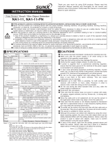
Figure 2.4: Main components of the DBW04 braking module
2.4 DBW04 IDENTIFICATION LABEL
The identification label of the DBW04 is located on the side of the module.
DBW04 Model
WEG part number
Manufacturing date
(12 corresponds to
week and I to year)
Serial number
Rated data
Figure 2.5: Example of identification label of the DBW04

DBW04 | 11
General Information
English
Figure 2.6: Location of the identification label
2.5 HOW TO SPECIFY THE DBW04 MODEL (SMART CODE)
To specify the model of the DBW04, fill out the respective fields for rated supply voltage and
rated output current in the intelligent code with the desired voltage and current values, as
example in Table 2.1 on page 11.
Table 2.1: Smart code
Braking Module Model
Example DBW04 0380 D 3848 S Z
Field
description
WEG braking
module series 04
Rated current - Inverter rated voltage Optional kit Character that
identifies the code end
Available
options
0380 = 380 A
(1)
0250 = 250 A
(2)
3848 = 380...480 V
(3)
5069 = 500...690 V
(4)
S = standard
product
(1) Available only for voltage of 380...480 V.
(2) Available only for voltage of 500...690 V.
(3) Available only for current of 380 A.
(4) Available only for current of 250 A.
Example: DBW040250D5069SZ corresponds to a braking module DBW04 of 250 A, for an
inverter with input voltage (power supply) from 500 V to 690 V.
2.6 RECEIVING AND STORAGE
The DBW04 is packaged and shipped in a cardboard box.
There is an identification label affixed to the outside of the package, identical to the one affixed
to the DBW04.

12 | DBW04
General Information
English
Verify whether:
The DBW04 nameplate corresponds to the purchased model.
Any damage occurred during transportation.
Report any damage immediately to the carrier that delivered your DBW04.
If the DBW04 is not installed soon, store it in a clean and dry location (temperature between -25 °C
and 60 °C (-13 °F and 140 °F)), with a cover to prevent dust accumulation inside it.

DBW04 | 13
Installation and Connection
English
3 INSTALLATION AND CONNECTION
This chapter describes the DBW04 electrical and mechanical installation procedures.
The guidelines and suggestions must be followed aiming personnel and equipment safety, as
well as the proper operation of the dynamic braking module.
3.1 ENVIRONMENTAL CONDITIONS
Avoid:
Direct exposure to sunlight, rain, high humidity, or sea-air.
Inflammable or corrosive gases or liquids.
Excessive vibration.
Dust, metallic particles, and oil mist.
Environment conditions for the operation of the inverter:
Temperature: -10 ºC to 45 ºC (14 °F to 113 °F) - nominal conditions (measured surrounding
the dynamic braking module).
From 45 ºC to 55 ºC (113 °F to 131 °F) - current derating of 2 % each °C (or 1.11 % each °F)
above 45 ºC (113 °F).
Air relative humidity: 5 % to 95 % non-condensing.
Altitude: up to 1000 m (3.300 ft) - nominal conditions.
From 1000 m to 4000 m (3.300 ft to 13.200 ft) - 1 % of current derating for each 100 m (or
0.3 % each 100 ft) above 1000 m (3.300 ft) altitude.
From 2000 m to 4000 m (6.600 ft to 13.200 ft) above sea level - maximum voltage reduction
(480 V for 380...480 V models) of 1.1 % for each 100 m (330 ft) above 2000 m (6.600 ft).
Pollution degree: 2 (according to EN50178 and UL508C), with non-conductive pollution.
Condensation must not originate conduction through the accumulated residues.
3.2 MECHANICAL INSTALLATION
Mount the module in the upright position on a flat surface.
Observe the clearances shown in Figure 3.1 on page 14 to allow the circulation of cooling air.
External dimensions and position of fixation points are presented in Section 7.3 MECHANICAL
DATA on page 31.
First put the screws on the surface where the module will be installed, install the module and
then tighten the screws. Four M6 screws are used (recommended torque: 8.5 N.m) for fixing
the module.
Do not install heat sensitive components just above the module.

14 | DBW04
Installation and Connection
English
100 mm (3.93 in)
130 mm (5.11 in)
40 mm (1.57 in)
40 mm (1.57 in)
50 mm (1.96 in)
Figure 3.1: Free spaces for ventilation
The DBW04 has a mechanical accessory for the mounting of connecting cables "+UD" and
"-UD," illustrated in Figure 3.2 on page 14. For further details, contact WEG.
Accessory to
assemble cables
Detail A
A
∅ 11.2 mm (0.44 in)
Figure 3.2: Accessory for the mounting cables of connections "+UD" and "-UD"

DBW04 | 15
Installation and Connection
English
3.3 ELECTRICAL INSTALLATION
DANGER!
The following information is merely a guide for proper installation. Comply with
applicable local regulations for electrical installations.
DANGER!
Make sure the AC power supply is disconnected before starting the installation.
3.3.1 Power Terminals, Grounding Points and Fuses
The connections of +UD and -UD (see Figure 3.3 on page 15) are performed by means of
two bolts M10 x 25 mm (0.98 in) (recommended torque: 30 N.m).
-UD +UD
Detail A
A
Figure 3.3: Input connections +UD and -UD
In Figure 3.4 on page 16 are presented the connections of the grounding and braking resistor.
The braking resistor is connected by means of bolts M10 x 25 mm (0.98 in) (recommended torque:
30 N.m). For the grounding, bolts M8 x 20 mm (0.78 in) are used (recommended torque: 10 N.m).

16 | DBW04
Installation and Connection
English
Braking resistor
BR
+UD
Figure 3.4: Connections of the grounding and braking resistor
Use cables with the gauge indicated in Table 3.1 on page 16 to connect the DBW04 braking
module.
Table 3.1: Connecting cables of the DBW04
Line
(V)
Current
(A)
Minimum Section of
the Resistor Cables
[mm
2
(AWG)]
Minimum Section of
the Cables for
+UD and -UD
[mm
2
(AWG)]
Minimum Section of
the Grounding Cable
[mm
2
(AWG)]
380-480 380 240 (2 x 4/0) 240 (2 x 4/0) 120 (4/0)
500-690 250 120 (4/0) 120 (4/0) 70 (2/0)
It is recommended to use fuses when the braking module is connected to a DC link with more
than one inverter. Two fuses must be installed, one for the +UD and another for the -UD. The
current of each fuse must be 630 Arms with i
2
t maximum of 1.440.000 A
2
s.
They must have an interruption capacity for direct voltage of 800 Vdc for the line 380...480 V,
1000 Vdc for the line 500...600 V and 1200 Vdc for the line 660...690 Vdc.

DBW04 | 17
Installation and Connection
English
3.3.2 Dimensioning of the Braking Resistor
For the proper dimensioning of the braking resistor, consider the application data, such as:
Desired deceleration time.
Load inertia.
Braking cycle.
In any case, the effective current and maximum braking current values presented in Table 7.1
on page 30 must be observed.
The maximum braking current defines the minimum ohm value allowed for the braking resistor.
The DC link voltage level for actuation of the rheostatic braking is defined by the setting of the
DIP Switch S2 (rheostatic braking actuation voltage), see Table 3.4 on page 22.
The braking resistor power is defined according to the deceleration time, load inertia and
resistive torque.
For most applications, it may be used a resistor with the ohm value indicated in Table 7.1 on
page 30 and power of 20 % of the rated power value of the driven motor.
Use resistors of STRIP or WIRE type in ceramic support, with proper insulation voltage and that
stand high instant powers in relation to the rated power.
For critical applications with very short braking times, high inertia loads (ex: centrifuges) or
with very short and frequent duty cycles, contact WEG, to define the most suitable resistor.
Note:
The effective braking current presented is just an orientative value, because it depends on the
braking cyclic ratio in the application. In order to obtain the effective braking current, use the
formula below, where t
br
is given in minutes and corresponds to the sum of the braking actuation
periods during the severest cycle of five minutes.
I
effective
= I
max
x
t
br
5
√
3.3.3 Installation of the Braking Resistor
Connect the braking resistor between the power terminals +UD and BR, see Figure 3.5 on
page 18.
Separate these power cables from the signal and control wiring. Dimension the cables according
to the application, observing the maximum and effective currents.
If the braking resistor is mounted within the inverter cabinet, take its energy into account when
dimensioning the ventilation of the cabinet.
In order to avoid the destruction of the resistor or risk of fire, include a thermal relay in series
with the resistor and/or a thermostat in contact with its housing, connected in such a way to
disconnect the input power supply of the inverter, as shown in Figure 3.5 on page 18.

18 | DBW04
Installation and Connection
English
NOTE!
Through the power contacts of the bimetallic overload relay circulates direct
current during the braking process.
External braking
resistor
Shield
Fuses
Contactor
Thermostat
Grid
Control
supply
DBW04
braking
module
+UD
BR
DC+DC-
XC4:1 (DIT-A)
XC4:2 (DIT-B)
XC4:4 (RL1-C1)
XC4:5 (RL1-NF1)
Frequency
inverter
Figure 3.5: Example of basic application circuit
3.3.4 Control Connections
The control connections (digital inputs/outputs), must be made at the CDB1 control board
terminal strip XC4. Refer to the Figure 3.7 on page 19.
Detail A
Scale 1:1
A
Figure 3.6: Location of the control board CDB1

DBW04 | 19
Installation and Connection
English
ATTENTION!
Provide independent conduits for the physical separation of signal, control
and power cables.
White LED: DC Voltage
Green LED: + 15 V
Green LED: DI Enable
N3: synchronism output (fiber optic emitter)
N2: synchronism input (fiber optic receiver)
Green LED: Brake On
Red LED: Fault
S1: line voltage:
S2: braking voltage
XP
P
N
XN
ON
ON
XC1
XC3
XC14
XC6
XC4
N2 N3
S1
S2
13
4
3
1
1
3 XC5 1
1314
41 41
NANA
K1
IN
N4
GND
OUT
K1
NF NF
B
1 2 3 4 5 6 7 8 9 10
B B B
CC
1 2
14
XC4
21
1
ON
XC2
5
1
CDB1
10772987
2 3 41
ON
Figure 3.7: Connection points of the CDB1 board
Table 3.2: Signals at connector XC4
XC4 Terminal Strip Function Specifications
1 DIT-A Braking resistor thermostat input NC - Normally closed contact
2 DIT-B
3 NO1 Digital output RL1:
with fault
Contact rating:
Maximum voltage: 240 Vac
Maximum current: 1 A
NC - Normally closed contact
C - Common
NO - Normally open contact
4 C1
5 NC1
6 NO2 Digital output RL2:
with ground fault
7 C2
8 NC2
9 DI1 Digital input 1:
General disable
Isolated digital input
High level ≥ 18 V
Low level ≤ 3 V
Input voltage ≤ 30 V
Input current: 11 mA @ 24 Vdc
10 COM1 Common point of the digital input DI1
Description of the control connections:
/