Electrolux EW30ES80RS Installation guide

Category
Microwaves
Type
Installation guide
INSTALLATION INSTRUCTIONS
30" ELECTRIC SLIDE-IN RANGE
P/N 318201633 (1602) Rev. C
English – pages 1-13
Spanish - pages 14-26
Français – pages 27-40
Printed in United States
Important Notes to the Installer
1. Read all instructions contained in these installation
instructions before installing range.
2. Remove all packing material from the oven and
the drawer compartments before connecting the
electrical supply to the range.
3. Observe all governing codes and ordinances.
4. Be sure to leave these instructions with the
consumer.
Important Note to the Consumer
Keep these instructions with your owner's guide for
future reference.
INSTALLATION AND SERVICE MUST BE PERFORMED BY A QUALIFIED
INSTALLER.
IMPORTANT: SAVE FOR LOCAL ELECTRICAL INSPECTOR'S USE.
READ AND SAVE THESE INSTRUCTIONS FOR FUTURE REFERENCE.
FOR YOUR SAFETY: Do not store or
use gasoline or other ammable vapors and liquids
in the vicinity of this or any other appliance.
Table of Contents
Important Safety Instructions .......................................... 2
Product & Cabinet Dimensions....................................3-4
To Avoid Breakage .......................................................... 5
Serial Plate Location....................................................... 6
Factory Connected Power Supply Cord ......................... 6
Power Supply Cord Kit ................................................... 6
Access to Terminal Block & Grounding Strap ................. 6
Electrical Connection to the Range .............................7-8
Cabinet Construction ................................................... 8-9
Range Installation ......................................................9-10
Leveling the range ........................................................ 10
Check Operation............................................................11
Anti-Tip Brackets Installation ................................... 12-13
CanadaUnited States
2
30" ELECTRIC SLIDE-IN RANGE INSTALLATION INSTRUCTIONS
• A child or adult can tip the range and
be killed.
• Verify the anti-tip device has been
installedtooororwallasper
installation instructions.
Tip Over Hazard
• Ensuretheanti-tipdeviceisre-engagedtoooror
wall when the range is moved.
• Do not operate the range without the anti-tip device
in place and engaged.
• Failure to follow these instructions can result in
death or serious burns to children and adults.
To check if the anti-tip bracket is installed
properly, use both arms and grasp
the rear edge of range back. Carefully
attempt to tilt range forward. When
properly installed, the range should not
tilt forward.
Refer to the anti-tip bracket installation instructions
supplied with your range for proper installation.
Cold temperatures can damage the
electronic control. When using the appliance for the
rsttime,orwhentheappliancehasnotbeenused
for an extended period of time, be certain the unit has
been in temperatures above 32°F (0°C) for at least 3
hours before turning on the power to the appliance.
Be sure your range is installed and grounded
properly by a qualied installer or service
technician.
• This range must be electrically grounded in
accordance with local codes or, in their absence,
with the National Electrical Code ANSI/NFPA No.
70—latest edition in United States or with CSA
Standard C22.1, Canadian Electrical Code, Part 1
in Canada.
• Theinstallationofappliancesdesignedfor
manufactured (mobile) home installation must conform
with Manufactured Home Construction and Safety
Standard, title 24CFR, part 3280 [Formerly the Federal
Standard for Mobile Home Construction and Safety,
title 24, HUD (part 280)] or when such standard
is not applicable, the Standard for Manufactured
Home Installation 1982 (Manufactured Home Sites,
Communities and Setups), ANSI Z225.1/NFPA
501A-latest edition, or with local codes in United States
and with CAN/CSA-Z240 MH in Canada.
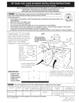
• Make sure the wall coverings around the range
can withstand the heat generated by the range.
• Before installing the range in an area covered with
linoleum or any other synthetic oor covering,
make sure the oor covering can withstand heat
at least 90°F (32,2°C) above room temperature
without shrinking, warping or discoloring. Do not
install the range over carpeting unless you place an
insulating pad or sheet of ¼" (0,64 cm) thick plywood
between the range and carpeting.
Never leave children alone or
unattended in the area where an appliance is in
use. As children grow, teach them the proper, safe
use of all appliances. Never leave the oven door open
when the range is unattended.
Stepping, leaning or sitting on the
door or drawer of this range can result in serious
injuries and can also cause damage to the range.
• Do not store items of interest to children in
the cabinets above the range. Children could be
seriously burned climbing on the range to reach items.
• To eliminate the risk of burns or re by reaching
over heated surface units, cabinet storage space
above the surface unit should be avoided. If
cabinet storage is to be provided the risk can be
reduce by installing a range hood that projects
horizontally a minimum of 5 inches beyond the
bottom of the cabinet.
• Do not use the oven as a storage space. This
creates a potentially hazardous situation.
• Never use your range for warming or heating the
room. Prolonged use of the range without adequate
ventilation can be dangerous.
• Do not store or use gasoline or other ammable
vapors and liquids near this or any other
appliance. Explosionsorrescouldresult.
• Reset all controls to the "off" position after using
a programmable timing operation.
This manual contains important safety symbols and instructions. Please pay attention to these symbols and
follow all instructions given.
This symbol will help alert you to situations that may cause serious bodily harm, death or
property damage.
This symbol will help alert you to situations that may cause bodily injury or property
damage.
IMPORTANT SAFETY INSTRUCTIONS
3
30" ELECTRIC SLIDE-IN RANGE INSTALLATION INSTRUCTIONS
Do not
install the unit in the
cabinet before reading
the next two pages.
A. HEIGHT
(Under Cooktop)
B. WIDTH
C. COOKTOP
WIDTH
D. TOTAL DEPTH TO FRONT OF
RANGE
35 3/4" (90,8 cm)
36 5/8" (93 cm)
30" (76,2 cm) 31 1/2" (80 cm) 28 5/16" (71,9 cm)
NOTE:
1
Do not pinch the power supply cord between the range and the wall.
2
Do not seal the range to the side cabinets.
3
24" (61 cm) minimum clearance between the cooktop and the bottom of the cabinet when the bottom
ofwoodormetalcabinetisprotectedbynotlessthan¼"(0,64cm)ameretardantmillboardor
covered with not less than No. 28 MSG sheet metal, 0,015" (0,4 mm) stainless steel, 0,024" (0,6 mm)
aluminum, or 0,020" (0,5 mm) copper.
30" (76,2 cm) minimum clearance when the cabinet is unprotected.
4
For cutouts less than 22 7/8" (58,1 cm), appliance will slightly show out of the cabinet.
5
Allow at least 19 ¼" (48,9 cm) clearance for door depth when it is open.
Open Door
(see note 5)
Side Panel
Product Dimensions
4
30" ELECTRIC SLIDE-IN RANGE INSTALLATION INSTRUCTIONS
G
E
½”min.
3/8”
min.
½”min.
13/16min.
4 1/4min.
1/8min.
1 5/8
min.
1 1/8"
(2,86 cm)
FRONT OF
CABINET
F
Ref.
22 7/8"(58,1 cm) min.
23 1/4"(59,05 cm) max.
(see Note 4)
IMPORTANT: Cabinet and countertop
width should match the cutout width.
***IMPORTANT: To avoid cooktop breakage for cutout width (E dimension) of more than 30 1/16" (76,4
cm), make sure the appliance is centered in the counter opening while pushing into it. Raise leveling
legs and the rear adjustable wheels at a higher position than the cabinet height (see page 5), insert
the appliance in the counter and then level. Make sure the unit is supported by the leveling legs at the
front and the wheels at the back and NOT by the cooktop itself.
E
E
E. CUTOUT WIDTH
(Countertop and cabinet)***
F. CUTOUT DEPTH
G. HEIGHT
OF COUNTERTOP
30±1/16"
(76,2±0,16 cm)
21 3/4" (55,2 cm) Min.
22 1/8" (56,2 cm) Max
24" (61 cm) Min. with backguard
35 7/8" (91,1 cm) Min.
36 5/8" (93 cm) Max.
Cabinet Dimensions
Shave Raised
Edge To Clear
Space for
31 1/2"
(80 cm)
Wide
Cooktop Rim.
Shaded
area shall
be clear
of any
openable
panel or
drawer.
Grounded Junction Box or Wall Outlet Should Be
Located 8" to 17" (20,3 - 43,2 cm) From Right
Cabinet and 2" to 4" (5,1-10,2 cm) From Floor
24" Min.
(61 cm) Min.
30" Min.
(76,2 cm) Min.
13"
(33 cm)
Locate Cabinet Doors 1" (2,5
cm) Min. From Cutout Opening
Approx. 1 7/8"
(4,8 cm)
18" Min.
(45,7 cm) Min.
30" Min.
(76,2 cm) Min.
(See Page 3, Note 3)
1 ½" Max.
(3,8 cm Max.)
Countertop
hatched surfaces
should be at &
leveled.
½" Min.
(1,3 cm) Min.
½" Min.
(1,3 cm) Min.
3/8" Min.
(0,95 cm) Min.
5
30" ELECTRIC SLIDE-IN RANGE INSTALLATION INSTRUCTIONS
Slide the unit into the cabinet. Make sure the center of the unit is
aligned with the center of the cabinet cut-out.
5
Remove the protective channels on each side of the cooktop (if
provided).
6
ThemetalangeundereachsideofthecooktopMUST be placed
over the cabinet countertop for proper unit support. The cooktop
should NOT rest directly on the countertop (see illustration 2) or else
it could cause damage to the cooktop voiding the warranty. Level the
unit if needed.
7
After the
installation, MAKE
SURE that the unit
is supported by
the leveling legs
and NOT by the
cooktop.
1
Thecounter-toparoundthecut-outshouldbeatandleveled(see
hatched area on illustration 1)
H1
H2
H3
H4
Illustration 1
Shave Raised
Edge to
Clear Space
for a 31½"
(80 cm) Wide
Cooktop.
1 ½" Max.
(3,8 cm Max.)
To avoid breakage: Do NOT handle or manipulate
the unit by the cooktop.
2
Before installing the unit,
measure the heights of
the two (2) cabinet sides
(H1-4), front and back
(see illustration 1) from
theoortothetopofthe
counter.
3
Level the range using the leveling legs and leveling
device(ifequipped)sothattheheightfromtheoor
to the underside of the cooktop glass frame is greater
than the tallest cabinet measurement by at least 1/16"
(0,16 cm) (see illustration 2).
4
If the appliance is equipped with leveling device: Remove and discard the two rear
leveling legs (in this case, they are only in place to stabilize the unit for the transport).
Illustration 2
To successfully
install the
range, the
initial level
height from
oorto
underside of
cooktop frame
should be at
least 1/16"
(0,16 cm) taller
than cabinet
sides as
measured in
step 2.
Metal
Flange
6
30" ELECTRIC SLIDE-IN RANGE INSTALLATION INSTRUCTIONS
Canada Style
Figure 1
3.
Power Supply Cord Kit (U.S.A.)
The user is responsible for connecting the power
supply cord to the connection block located behind the
back panel access cover.
This appliance may be connected by means of
permanent"hardwiring";exiblearmoredor
nonmetallic shielded copper cable (when local code
allow it) or by means of a power supply cord kit.
NOTE: Electric Slide-in Range is shipped from factory
with11/8"(2,9cm)dia.holeasshownongure3.Ifa
larger hole is required, punch out the knockout.
Risk of re or electrical shock
exists if an incorrect size range cord kit is used,
the Installation Instructions are not followed, or the
strain relief bracket is discarded.
For mobile homes, new installations or recreational
vehicles, use only a power supply kit designed for a
range at 125V/250V 50A recommended (minimum
40A). Cord must have either 3 (when local code
permits grounding through neutral) or 4 conductors.
Terminal on end of wires must be either closed loop or
open spade lug with upturned ends. Cord must have
strain-relief clamp.
Do not loosen the nuts which
secure the factory-installed range wiring to
terminal block while connecting range. Electrical
failure or loss of electrical connection may occur.
4.
Access to Terminal Block &
Grounding Strap (U.S.A.)
Electrical Shock Hazard
• Disconnect power to the circuit breaker or fuse
box before making the electrical connection.
• Electrical ground is required on this appliance.
• Do not connect to the electrical supply until
appliance is permanently grounded.
• This appliance must be connected to a
grounded, metallic, permanent wiring system,
or a grounding connector should be connected
to the grounding terminal or wire lead on the
appliance.
Failure to do any of the above could result in a
re, personal injury or electrical shock.
2.
Factory Connected Power
Supply Cord (Canada only)
This range is equipped with a factory-connected power
cord (see Figure 1). Cord must be connected to a
grounded 120/240 volt or 120/208 volt range outlet. If
nooutletisavailable,haveoneinstalledbyaqualied
electrician.
This appliance is manufactured
with the frame grounded by connection of a
grounding strap between the neutral power
supply terminal and the frame. If used in USA,
in a new branch circuit installation (1996 NEC),
mobile home or recreational vehicle, where
local code do not permit grounding through
neutral (white) wire or in Canada; remove the
grounding strap from the frame and cut the
other end, near the neutral terminal. Connect
the appliance in usual manner.
1.
Serial Plate Location
Youwillndthemodeland
serial number printed on the
serial plate. The serial plate is
located as shown.
Remember to record the serial
number for future reference.
Remove the wire cover here
for access to terminal block
Figure 2
7
30" ELECTRIC SLIDE-IN RANGE INSTALLATION INSTRUCTIONS
Four Conductor Wire Connection to Range
Where local codes DO NOT permit connection of the
frame grounding conductor to the neutral wire of the
copper power supply cord (see Figure 4):
1. Remove the screw holding the rear wire cover,
then remove the rear wire cover (access cover)
to expose range terminal connection block (see
Figure 2).
2. Remove the grounding strap. Remove the screw
that holds the strap against the appliance. Cut the
strap off at the terminal block, or bend the strap
back and forth to break it from the terminal block.
5.
Electrical Connection to the
Range (U.S.A.)
Three Conductor Wire Connection to
Range
If local codes permit connection of the frame grounding
conductor to the neutral wire of the copper power
supply cord (see Figure 3):
1. Remove the screw holding the rear wire cover,
then remove the rear wire cover (access cover)
to expose range terminal connection block (see
Figure 2).
2. Using the nuts supplied in the literature package,
connect the neutral of the copper power supply
cord to the center silver-colored terminal of the
terminal block, and connect the other wires to the
outer terminals. Match wires and terminals by color
(red wires connected to the right terminal, black
wiresconnectedtotheleftterminal)(seegure3).
3. Put back the rear wire cover using the screw
removed on step 1.
Figure 3
Silver Colored Terminal
1 1/8" (2,9 cm) Dia.
Direct Connection
Hole. Punch Out
Knockout for 1 3/8"
(3,5 cm) Dia. Cord
Kit Hole.
To 240 V
Receptacle
A User Supplied
Strain-relief Must
Be Installed at This
Location.
Black
Wire
Terminal
Block
Cord
Mounting
Plate
Neutral
(White Wire)
Grounding
Strap
Red Wire
DO NOT loosen the screws that attach the terminal
block to the appliance.
3. Using the nuts supplied with the literature package,
connect the ground wire (green) of the copper
power supply cord to the frame of the appliance with
the ground screw, using the hole in the frame where
the ground strap was removed (see Figure 4).
4. Connect the neutral of the copper power supply
cord to the center silver-colored terminal of the
terminal block, and connect the other wires to the
outer terminals. Match wires and terminals by color
(red wires connected to the right terminal, black
wires connected to the left terminal).
5. Put back the rear wire cover using the screw
removed on step 1.
Direct Electrical Connection to the Circuit
Breaker, Fuse Box or Junction Box
Disconnect power to the circuit breaker
or fuse box before making the electrical connection.
If the appliance is connected directly to the circuit
breaker,fuseboxorjunctionbox,useexible,armored
or nonmetallic sheathed copper cable (with grounding
wire). Supply a U.L. listed strain-relief at each end of
the cable. At the appliance end, the cable goes through
the Direct Connection Hole (see Figure 4) on the Cord
Mounting Plate. Wire sizes (copper wire only) and
connections must conform to the rating of the appliance.
Where local codes permit connecting the
appliance-grounding conductor to the neutral
(white) wire (see Figure 5):
Terminal Block
Silver Colored Terminal
Red
Wire
Neutral
(White Wire)
Ground (Bare
Copper Wire)
To 240 V
Receptacle
A User Supplied
Strain-relief Must
Be Installed at
This Location
Black Wire
1 1/8" (2,9
cm) Dia.
Direct
Connection
Hole. Punch
Out Knockout
for 1 3/8" (3,5
cm) Dia. Cord
Kit Hole.
Figure 4
8
30" ELECTRIC SLIDE-IN RANGE INSTALLATION INSTRUCTIONS
1. Be sure that no power is supplied on the cable from
residence.
2. DO NOT remove the grounding strap for 3-wire
installation.
3. In the circuit breaker, fuse box or junction box:
a) Connect the green (or bare copper) wire, the white
appliance cable wire, and the neutral (white) wire
together.
b) Connect the 2 black wires together.
c) Connect the 2 red wires together.
Where local codes DO NOT permit connecting
the appliance-grounding conductor to the neutral
(white) wire, or if connecting to 4-wire electrical
system (see Figure 6):
1. Be sure that no power is supplied on the cable
from residence.
2. Remove the grounding strap from the terminal
block and from the appliance frame.
3. In the circuit breaker, fuse box or junction box:
a) Connect the white appliance cable wire to the
neutral (white) wire.
b) Connect the 2 black wires together.
c) Connect the 2 red wires together.
d) Connect the green (or bare copper) grounding
wire to the grounding wire of the circuit breaker,
fuse box or junction box.
Figure 5 - 3-Wire (Grounded Neutral) Electrical
System (Example: Junction Box)
Cable from Residence
Junction
Box
White Wire
U.L.-listed Conduit
Connector (or CSA
listed)
Cable from
Appliance
Green
(or Bare Copper)
Wire
Red
Wires
Neutral
(white) Wire
Black
Wires
U.L.-listed Conduit
Connector (or CSA
listed)
Figure 6 – 4-Wire Electrical System
(Example: Junction Box)
Cable from Residence
Black
Wires
Junction
Box
White Wire
Cable from
Appliance
Green (or Bare
Copper) Wire
Red
Wires
White Wire
Green (or Bare
Copper) Wire
Min.
Cutout
Width
Formed or tile countertop
trimmed ¾" (1,9 cm) back at
front corners of countertop
opening.
Figure 7
6.
Cabinet Construction
6.1
To eliminate the risk of burns
orrebyreachingoverheatedsurfaceunits,donot
have cabinet storage space above the range. If there
is cabinet storage space above range, reduce risk
by installing a range hood that projects horizontally
a minimum of 5" (12,7 cm) beyond the bottom of the
cabinet.
6.2
Countertop Preparation
• Thecooktopsidesoftherangetoverthecutout
edge of your countertop.
• Ifyouhaveasquare nish (at) countertop, no
countertop preparation is required. Cooktop sides lay
directly on edge of countertop.
• Formed front-edged countertops must have
moldededgeshavedat3/4"(1,9cm)fromeach
front corner of opening (Figure 7).
• Tile countertops may need trim cut back 3/4" (1,9
cm) from each front corner and/or rounded edge
attened(Figure7).
If the existing cutout width is greater than 30
1/16" (76,4 cm), reduce the ¾" (1,9 cm) dimension.
• Countertop must be level. Place a level on the
countertop,rstsidetoside,thenfronttoback.If
the countertop is not level, the range will not be
level. The oven must be level for satisfactory baking
results.Cooktopsidesofrangetoveredgesof
countertop opening
9
30" ELECTRIC SLIDE-IN RANGE INSTALLATION INSTRUCTIONS
Figure 8
Figure 9
Range
Anti-Tip Bracket
Floor Mount
Floor
Rear of Range
Wall
Mount
Wall
1. Drawacenterline(CL)ontheoorwheretherange
shouldbeinstalled.Alsodrawalineontheoorat
the range back position if there is no wall.
2. Unfoldpapertemplateandplaceitatontheoor
with the right rear corner positioned exactly on the
intersection of the center and back lines you just
drew before. (Use the diagram below to locate
brackets if template is not available. (Figure 8))
3. Markontheoor(orwall)thelocationofthe
mounting holes shown on the template. For easier
installation, 3/16" (0,48 cm) diameter pilot holes 1/2"
(1,27cm)deepcanbedrilledintotheoor(orwall).
4. Removetemplateandplacebracketonoor.Lineup
holesinbracketwithmarksonoor/wallandattach
with screws provided. Bracket must be secured to
solidoororwall(Figure9).Ifattachingtoconcrete
oor,rstdrill3/16"(0,48cm)dia.pilotholesusing
masonry drill bit.
5. Be sure the 4 levelling legs are at the highest
position they can be.
6. Slide range into place making sure structure of the
range is trapped by the anti-tip bracket (Figure 9).
Lower the range by adjusting the levelling legs until
the underside of the cooktop is sitting level on the
countertop. Refer to “Levelling the Range” section.
7. After installation, verify that the anti-tip bracket is
engaged by grasping the top rear edge of the range
and carefully attempt to tilt it forward to make sure
range is properly anchored.
7.
Anti-Tip Brackets Installation
7.1
Models Equipped with Leveling Device
To reduce the risk of tipping of the
range,therangemustbesecuredtotheoorby
properly installed anti-tip bracket and screws packed
with the range. These parts are located in the oven.
Failure to install the anti-tip bracket will allow the range
to tip over if excessive weight is placed on an open door
or if a child climbs upon it. Serious injury might result
from spilled hot liquids or from the range itself.
Follow the instructions below to install the anti-tip
brackets.
If range is ever moved to a different location, the anti-
tip brackets must also be moved and installed with the
range.
Tools Required:
Adjustable Wrench
Ratchet
Drill & 1/8" (0,32 cm) bit
5/16" (0,8 cm) Nutdriver
Level
Theanti-tipbracketattachestotheoor(orbackwall)
at the back of the range to prevent range from tipping.
Whenfasteningbrackettotheoor,besurethatscrews
do not penetrate electrical wiring or plumbing. The
screws provided will work in either wood or concrete.
(
C
L = Center line)
10
30" ELECTRIC SLIDE-IN RANGE INSTALLATION INSTRUCTIONS
B. Drill Pilot Holes and Fasten Bracket - Drill a 1/8"
(0,3 cm) pilot hole where screws are to be located. If
bracket is to be mounted to the wall, drill pilot hole at
an approximate 20° downward angle. If bracket is to be
mountedtomasonryorceramicoors,drilla3/16"(0,5
cm) pilot hole 1-3/4" (4,4 cm) deep. The screws provided
may be used in wood or concrete material. Use a 5/16"
(0,8cm)nut-driveroratheadscrewdrivertosecurethe
bracket in place.
C. Level and position the range - Slide range to its
nalposition.Inserttherangelevelinglegintheanti-tip
bracket. Visually verify if the anti-tip bracket is engaged.
Lower the range by adjusting the 4 leveling legs
alternatively until the range is level. Check if the range
is level by placing a spirit level on the oven rack. Take
2 readings with the spirit level placed diagonally; take a
reading in one direction and then in the other direction.
Level the range if necessary by adjusting the leveling
legs.
Leg
Leveler
Raise
Lower
FASTEN BRACKET
(W
ALL OR FLOOR MOUNTING)
Leveling leg
Wall mount
Floor Mount
Anti-Tip Bracket
Rear of Range
Wall Plate
7.2
Models Equipped with Leveling Legs
To reduce the risk of tipping of the
range,therangemustbesecuredtotheoorbythe
properly installed anti-tip bracket and screws packed
with the range. Failure to install the anti-tip bracket will
allow the range to tip over if excessive weight is placed
on an open door or if child climbs upon it. Serious injury
might result from spilled hot liquids or from the range
itself.
If range is ever moved to a different location, the anti-
tip bracket must also be moved and installed with the
range.
Instructions are provided for installation in wood or
cementoor.Whenfasteningtooor,besurethat
screws do not penetrate electrical wiring or plumbing.
A. Locate the Bracket Using the Template - Locate
the bracket position (right or left side) by placing the
templatesymmetricallytothecenterofthenalrange
position. Mark the location of the screw holes, shown on
template.
Figure 12
Figure 13
Figure 14
Figure 11
Figure 10
Range side
11
30" ELECTRIC SLIDE-IN RANGE INSTALLATION INSTRUCTIONS
IMPORTANT
If Accessories Needed :
Installation With Backguard
The cutout depth of (21 3/4" (55,2 cm) Min., 22 1/8"
(56,2 cm) Max.) needs to be increased to 24" (61
cm) when installing a backguard.
Installation With End Panel
A End Panel kit can be ordered through a Service
Center.
Installation With Side Panels
A Side Panels kit can be ordered through a Service
Center. Note: Install cabinet doors 32" (81,3 cm) min.
apart so as not to interfere with range door opening.
8.
Range
Installation
Important Note:
Door removal is not
a requirement for
installation of the
range, but is an added
convenience. Refer to
the Use and Care Guide
for oven door removal instructions.
Standard Installation
8.1
The range cooktop overlaps the countertop at
thesidesandtherangerestsontheoor.The
cooktop is 31½" (80 cm) wide.
8.2
Install base cabinets 30" (76,2 cm) apart. Make
sure they are plumb and level before attaching
cooktop. Shave raised countertop edge to clear
31½" (80 cm) wide range top rim.
8.3
Install cabinet doors 32" (81,3 cm) min. apart so
as not to interfere with range door opening.
8.4
Cutout countertop exactly as shown on page 4.
Model equipped with leveling device or Model
equipped with leveling legs
For models equipped with Leveling Device:
8.5
Make sure the front leveling legs and the rear
leveling device are setup higher than the height
of the cabinet.
8.6
Install the anti-tip bracket at
this point before placing the range at its nal
position. Follow the installation instructions
on page 9 or on the anti-tip bracket template
supplied with the range.
8.7
To provide an optimum installation, the top
surface of the countertop must be level and
at(lieonthesameplane)aroundthe3sides
that are adjacent to range cooktop. Proper
adjustmentstomakethetopatshouldbemade
or gaps between the countertop and the range
cooktop may occur.
8.8
To reduce the risk of damaging
your appliance, do not handle or manipulate it by the
ceramic glass. Manipulate with care.
8.9
Position range in front of the cabinet opening.
8.10
Make sure the cooktop glass that overhangs the
countertop clears the countertop before sliding
range into position. If necessary, raise the unit by
lowering the leveling legs.
8.11
Slide the range into the cutout opening and
center it before leveling it.
8.12
Level the range (see section 9). Theoor
where the range is to be installed must be level.
Follow the instructions under "Leveling the
Range- Models Equipped with Leveling Device".
8.13
On models with a leveling device, remove the
rear legs and discard. Adjust the leveling legs
on the front of the appliance so that the cooktop
glass clears the countertop. Level the appliance
(see Leveling the range: Models Equipped
with Leveling Device). The glass should not be
supported by the countertop or any hatched or
shaved areas of the countertop.
For models equipped with Leveling Leg only (no
leveling device):
8.5
Make sure the four leveling legs (front and rear)
are setup higher than the height of the cabinet.
8.6
Install the anti-tip bracket at
this point before placing the range at its nal
position. Follow the installation instructions
on page 10 or on the anti-tip bracket template
supplied with the range.
8.7
To provide an optimum installation, the top
surface of the countertop must be level and
at(lieonthesameplane)aroundthe3sides
that are adjacent to range cooktop. Proper
adjustmentstomakethetopatshouldbemade
or gaps between the countertop and the range
cooktop may occur.
8.8
To reduce the risk of damaging
your appliance, do not handle or manipulate it
by the ceramic glass. Manipulate with care.
8.9
Position range in front of the cabinet opening.
8.10
Make sure that the glass which overhangs the
countertop clears the countertop. If necessary,
raise the unit by lowering the leveling legs.
8.11
Level the range(seesection9).Theoor
where the range is to be installed must be level.
Follow the instructions under "Leveling the
Range-Models Equipped with Leveling Legs".
8.12
Slide the range into the cutout opening.
Figure 15
12
30" ELECTRIC SLIDE-IN RANGE INSTALLATION INSTRUCTIONS
9.
Leveling the range
9.1
Models Equipped with Leveling Device
Level the range after installation in the cutout
opening.
1. Open the range drawer. The leveling screws control
the height of the rear wheels.
2. Adjust the appliance wheels and legs as follows
until the underside of the cooktop surface is sitting
level on the countertop (Figure 16).
a. To adjust the front legs, use a wrench on
the leg base and turn clockwise to lower or
counterclockwise to raise.
b. To adjust the rear wheels, use a ratchet
or a nutdriver and turn the leveling screws
counterclockwise to lower or clockwise to raise.
3. Check if the range is level by installing an oven rack
in the center of the oven and placing a level on the
rack (Figure 17).
4. Take 2 readings with the level placed diagonally in
one direction and then the other. Level the range,
if necessary, by adjusting the leveling legs and
wheels.
5. If the range cannot be level, contact a carpenter to
correctsaggingorslopingoor.
Figure 16
9.2
Models Equipped with Leveling Legs
Level the range and set cooktop height before
installation in the cut-out opening.
1. Install an oven rack in the center of the oven.
2. Place a level on the rack (see Figure 17). Take 2
readings with the level placed diagonally in one
direction and then the other. Level the range, if
necessary, by adjusting the 4 leg levelers with a
wrench (see Figure 16).
3. Taking care to not damage the countertop, slide
range into cutout opening and double check for
levelness.
Figure 17
13
30" ELECTRIC SLIDE-IN RANGE INSTALLATION INSTRUCTIONS
11.
Check Operation
Refer to the Use and Care Manual packaged with
the range for operating instructions and for care and
cleaning of your range.
Do not touch the elements. They may
be hot enough to cause burns.
Remove all packaging from the oven before testing.
11.1
Operation of Surface Elements
Turn on each of the four surface elements and check to
see that they heat. Check the surface element indicator
light(s), if equipped.
11.2
Operation of Oven Elements
The oven is equipped with an electronic oven control.
Each of the functions has been factory checked before
shipping. However, it is suggested that you verify the
operation of the electronic oven controls once more.
Refer to the Use and Care Manual for operation.
Follow the instructions for the Clock, Timer, Bake, Broil,
Convection (some models) and Clean functions.
Bake–After setting the oven to 350°F (177°C) for
baking, the lower element in the oven should become
hot and heat the bottom of the oven cavity.
Broil–When the oven is set to BROIL, the upper
element in the oven should become red.
Clean–When the oven is set for a self-cleaning cycle,
the upper element should become red during the
preheat portion of the cycle. After reaching the self-
cleaning temperature, the lower element will become
red.
Convection (some models)–When the oven is set to
CONV. BAKE/ROAST at 350°F (177°C), or when the
oven is preheating for a BAKE function, the elements
cycle off on and off alternately and the convection fan
will turn. The convection fan will stop turning when
the oven door is opened during convection baking or
roasting.
Warmer (some models)–Set the control to HI and
check to see the drawer is heating.
When All Hookups are Complete
Make sure all controls are left in the OFF position.
Model and Serial Number Location
The serial plate is located on the oven front frame
behind the oven door (see section 1).
When ordering parts for or making inquiries about your
range, always be sure to include the model and serial
numbers and a lot number or letter from the serial plate
on your range.
Before You Call for Service
Read the Before you call list and operating instructions
in your Use and Care Manual. It may save you time
and expense. The list includes common occurrences
that are not the result of defective workmanship or
materials in this appliance.
Refer to the warranty and service information in your
Use and Care Manual for our phone number and
address. Please call or write if you have inquiries about
your range product and/or need to order parts.
Decorative Trim
Screw (3)
Distance
between the
oorand
the surface
underneath
the cooktop
frame.
Figure 18
10.
Decorative Rear Trim
Installation (some models)
1. Disconnect the power from the range.
2. Make sure the range is leveled.
3. Pull range toward you.
4. Takethedistancebetweentheoorandthe
surface underneath the cooktop frame.
5. Mark that distance on the wall where the
decorative trim will be installed.
6. Draw a line.
7. Place the top of the decorative trim under that line.
8. Usingthescrewsprovidedxthedecorativetrim
into the wall.
9. Slide the range back into position and reconnect
the power source (the bottom of the cooktop
should be located over the decorative trim).
  • Page 1 1
  • Page 2 2
  • Page 3 3
  • Page 4 4
  • Page 5 5
  • Page 6 6
  • Page 7 7
  • Page 8 8
  • Page 9 9
  • Page 10 10
  • Page 11 11
  • Page 12 12
  • Page 13 13
  • Page 14 14
  • Page 15 15
  • Page 16 16
  • Page 17 17
  • Page 18 18
  • Page 19 19
  • Page 20 20
  • Page 21 21
  • Page 22 22
  • Page 23 23
  • Page 24 24
  • Page 25 25
  • Page 26 26
  • Page 27 27
  • Page 28 28
  • Page 29 29
  • Page 30 30
  • Page 31 31
  • Page 32 32
  • Page 33 33
  • Page 34 34
  • Page 35 35
  • Page 36 36
  • Page 37 37
  • Page 38 38
  • Page 39 39
  • Page 40 40

Electrolux EW30ES80RS Installation guide

Category
Microwaves
Type
Installation guide

Ask a question and I''ll find the answer in the document

Finding information in a document is now easier with AI