Page is loading ...
Serial number:
99046144C
WWW.BROAN.COM WWW.BROAN.CA
WW
WW.BR
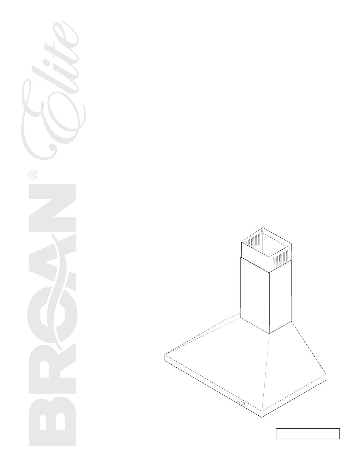
CHIMNEY
RANGE HOOD
EW48 Series
INSTALLATION, USE
AND CARE MANUAL

2
TO REDUCE THE RISK OF FIRE, ELECTRIC SHOCK OR
INJURY TO PERSONS, OBSERVE THE FOLLOWING:
1. Use this unit only in the manner intended by the manufacturer.
If you have questions, contact the manufacturer at the address
or telephone number listed in the warranty.
2. Before servicing or cleaning unit, switch power off at service
panel and lock service disconnecting means to prevent
power from being switched on accidentally. When the service
disconnecting means cannot be locked, securely fasten a
prominent warning device, such as a tag, to the service panel.
3. Installation work and electrical wiring must be done by
qualified personnel in accordance with all applicable codes
and standards, including fire-rated construction codes and
standards.
4. Sufficient air is needed for proper combustion and exhausting
of gases through the flue (chimney) of fuel burning equipment
to prevent backdrafting. Follow the heating equipment
manufacturer’s guidelines and safety standards such as
those published by the National Fire Protection Association
(NFPA) and the American Society for Heating, Refrigeration
and Air Conditioning Engineers (ASHRAE) and the local code
authorities.
5. When cutting or drilling into wall or ceiling, do not damage
electrical wiring and other hidden utilities.
6. Ducted fans must always be vented to the outdoors.
7. Do not use this unit with any solid-state speed control device.
8. To reduce the risk of fire, use only metal ductwork.
9. This unit must be grounded.
10. When applicable local regulations comprise more restrictive
installation and/or certification requirements, the aforementioned
requirements prevail on those of this document and the installer
agrees to conform to these at his own expense.
TO REDUCE THE RISK OF A RANGE TOP GREASE FIRE:
a) Never leave surface units unattended at high settings. Boilovers
cause smoking and greasy spillovers that may ignite. Heat oils
slowly on low or medium settings.
b) Always turn hood ON when cooking at high heat or when
flambeing food (i.e.: Crêpes Suzette, Cherries Jubilee,
Peppercorn Beef Flambé).
c) Clean ventilating fans frequently. Grease should not be allowed
to accumulate on fan, filters or in exhaust ducts.
d) Use proper pan size. Always use cookware appropriate for the
size of the surface element.
1. For indoor use only.
2. For general ventilating use only. Do not use to exhaust
hazardous or explosive materials and vapors.
3. To avoid motor bearing damage and noisy and/or unbalanced
impeller, keep drywall spray, construction dust, etc. off power unit.
4. Your hood motor has a thermal overload which will automatically
shut off the motor if it becomes overheated. The motor will
restart when it cools down. If the motor continues to shut off
and restart, have the hood serviced.
5. The minimum hood distance above cooktop must not be less
than 24". For best capture of cooking impurities, the bottom
of the hood should be at a maximum of 30" above cooking
surface.
6. Two installers are recommended because of the large size and
weight of this unit.
7. To reduce the risk of fire and to properly exhaust air, be sure to
duct air outside — Do not exhaust air into spaces within walls
or ceiling or into attics, crawl space or garage.
8. Because of the high exhausting capacity of this unit, you
should make sure enough air is entering the house to replace
exhausted air by opening a window close to or in the kitchen.
9. To reduce the risk of fire and electrical shock, the Broan Elite
EW48 Series models should only be installed with their own
built-in blower.
10. When used in recirculation mode, to reduce the risk of fire and
shock, use only conversion kit model ARKEW48.
11. Please read specification label on product for further information
and requirements.
WARNING
!
CAUTION
WARNING
!
TO REDUCE THE RISK OF INJURY TO PERSONS IN THE
EVENT OF A RANGE TOP GREASE FIRE, OBSERVE
THE FOLLOWING*:
1. SMOTHER FLAMES with a close-fitting lid, cookie sheet or
metal tray, then turn off the burner. BE CAREFUL TO PREVENT
BURNS. IF THE FLAMES DO NOT GO OUT IMMEDIATELY,
EVACUATE AND CALL THE FIRE DEPARTMENT.
2. NEVER PICK UP A FLAMING PAN — You may be burned.
3. DO NOT USE WATER, including wet dishcloths or towels —
This could cause a violent steam explosion.
4. Use an extinguisher ONLY if:
A. You own a Class ABC extinguisher and you know how to
operate it.
B. The fire is small and contained in the area where it started.
C. The fire department has been called.
D. You can fight the fire with your back to an exit.
* Based on “Kitchen Fire Safety Tips” published by NFPA.
In U.S.A., register your range hood online at www.broan.com
In Canada, register your range hood online at www.broan.ca
INTENDED FOR DOMESTIC COOKING ONLY
INSTALLER: LEAVE THIS MANUAL WITH HOMEOWNER.
HOMEOWNER: USE AND CARE INFORMATION ON PAGE 10.
READ AND SAVE THESE INSTRUCTIONS
! !
3
1. P REPARE INSTALLATION. . . . . . . . . . . . . . . . . . . . . . . . . . . . 3
2. SELECT INSTALLATION TYPE . . . . . . . . . . . . . . . . . . . . . . . . . 3
3. BUILD FRAMEWORK . . . . . . . . . . . . . . . . . . . . . . . . . . . . . . 4
4. I
NSTALL UPPER FLUE MOUNTING BRACKET (DUCTED INSTALLATION ONLY) 4
5. INSTALL PLENUM (NON-DUCTED INSTALLATION ONLY) . . . . . . . . . 4
6. REMOVE GREASE FILTER(S). . . . . . . . . . . . . . . . . . . . . . . . . 5
7. I NSTALL THE HOOD. . . . . . . . . . . . . . . . . . . . . . . . . . . . . . . 5
8. CONNECT WIRING . . . . . . . . . . . . . . . . . . . . . . . . . . . . . . . 6
9. D
UCT CONNECTION . . . . . . . . . . . . . . . . . . . . . . . . . . . . . . 7
10. PREPARE THE DECORATIVE FLUE. . . . . . . . . . . . . . . . . . . . . . 8
11. INSTALL THE DECORATIVE FLUE. . . . . . . . . . . . . . . . . . . . . 8-9
12. R
EINSTALL GREASE FILTER(S) . . . . . . . . . . . . . . . . . . . . . . . 9
13. OPERATION . . . . . . . . . . . . . . . . . . . . . . . . . . . . . . . . . . 10
14. CARE . . . . . . . . . . . . . . . . . . . . . . . . . . . . . . . . . . . . . 10
15. REPLACEMENT PART S . . . . . . . . . . . . . . . . . . . . . . . . . . . . 11
16. WARRANTY . . . . . . . . . . . . . . . . . . . . . . . . . . . . . . . . . . 12
TABLE OF CONTENTS
1. PREPARE INSTALLATION
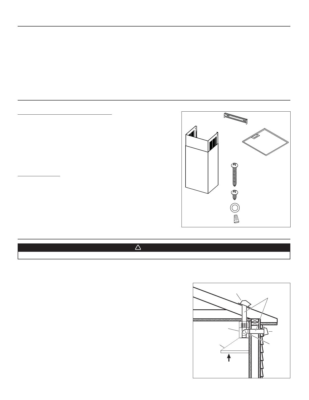
NOTE: Before proceeding to the installation, check the contents of the box. If items are missing or damaged, contact the retailer.
Make sure that the following items are included:
- Hood
- Decorative flue assembly (lower and upper flues)
- Upper flue mounting bracket
- Aluminum grease filter(s) (1 for 24-in. width hood, 2 for 30-in. and
36-in. width hoods)
- Installation instructions
- Parts bag: 6 M4 x 38 Phillips 9 mm round head mounting screws,
2 M4 x 12 Phillips 9 mm round head screws,
2 washers and 3 wire connectors
Parts sold separately:
- Ducts, elbows, wall and roof caps.
- Optional flue extension for ceilings of 9 ft. or more: models AEEW48SS
(stainless steel), AEEW48BLS (black stainless steel) or AEEW48WH (white).
- Non-duct kit model ARKEW48, mandatory for non-ducted installation.
NOTE: During installation, protect countertop and/or cooktop.
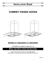
2. SELECT INSTALLATION TYPE
2.1 NON-DUCTED INSTALLATION
The ARKEW48 non-duct kit is required for a non-ducted installation.
2.2 DUCTED INSTALLATION
Plan where and how the ductwork will be installed.
A straight, short duct run will allow the hood to perform most efficiently. Long duct
runs, elbows and transitions will reduce the performance of the hood. Use as few
of them as possible. Larger ducting may be required for longer duct runs.
Install wall or roof cap. Connect 6” round metal ductwork to cap and work back
towards the hood location. Use 2” metal foil duct tape to seal the joints.
2.3 ALL INSTALLATIONS
The minimum hood distance above cooktop is 24”. A maximum of 30” above
cooktop is recommended for best capture of cooking impurities.
Distances over 30” are at the installer and users discretion providing that ceiling
height and decorative flue length allow it.
NOTE: Ceilings of 9 ft. or more require flue extension model AEEW48SS (stainless
steel), AEEW48BLS (black stainless steel) or AEEW48WH (white).
6” ROUND
DUCT
ROOF CAP
6” ROUND
ELBOW
WALL
CAP
HOOD
DECORATIVE
FLUE
HH0281A
24” MINIMUM ABOVE
COOKING
SURFACE
WARNING
!
When performing installation, servicing or cleaning the unit, it is recommended to wear safety glasses and gloves.
HR0224A
(1) DECORATIVE FLUE
ASSEMBLY
(1) UPPER FLUE
MOUNTING
BRACKET
(1 OR 2) GREASE FILTER(S)
(6) M4
X 38 PHILLIPS
ROUND HEAD SCREWS
(2) M4
X 12 PHILLIPS
ROUND HEAD SCREWS
(2) WASHERS
(3) WIRE CONNECTORS
4
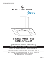
3. BUILD FRAMEWORK
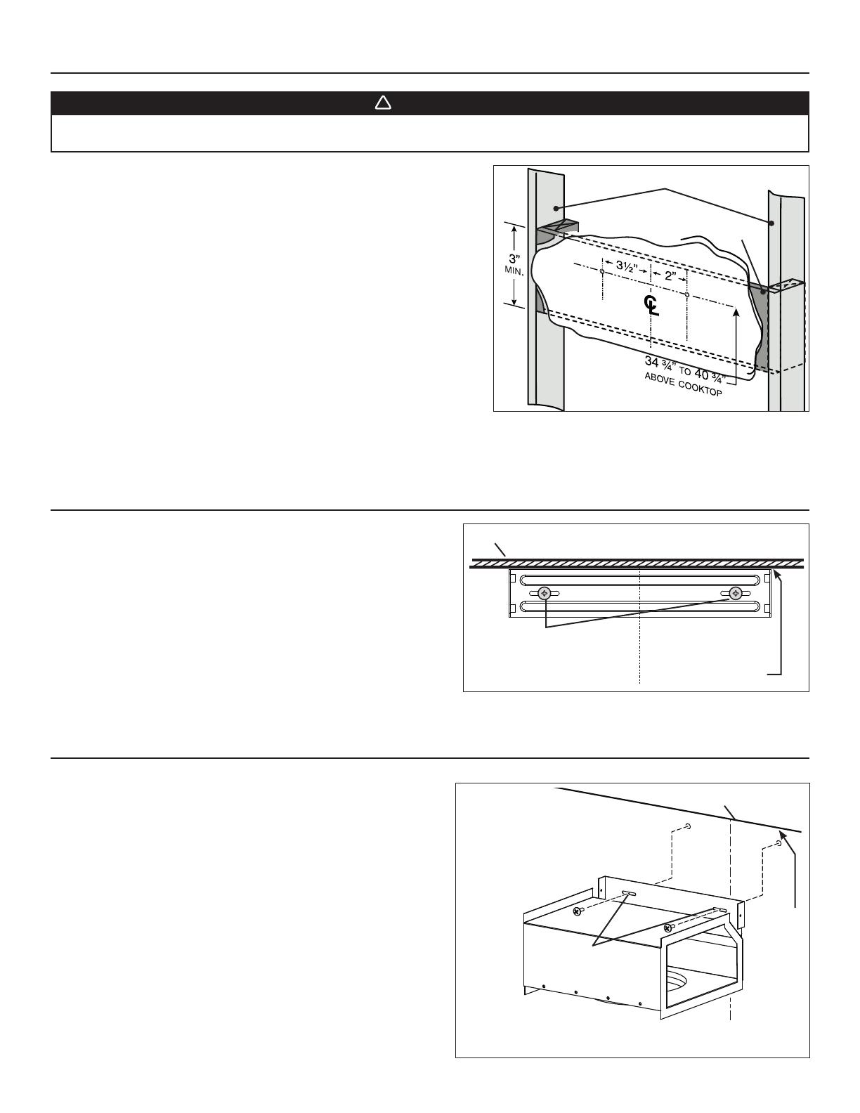
HD1151A
FRAMING BEHIND DRYWALL
WALL STUDS
34 ¾” = BOTTOM OF HOOD 24” ABOVE COOKTOP
40 ¾” = BOTTOM OF HOOD 30” ABOVE COOKTOP
WARNING
!
• When cutting or drilling into wall, do not damage electrical wiring and other hidden utilities.
• When building framework, always follow all applicable construction codes and standards.
Construct wood wall framing that is even with the surface of wall studs.
Wood wall framing must be at least 1/2” thick and 3” high. Fasten wood wall
framing to wall studs for a solid installation.
Make sure that the height of the framing will allow the retaining screws to be
secured to the framing within the dimensions shown.
After wall surface is finished, using a level, draw a vertical line up to the
ceiling starting from the center of the planned hood location. Measure and
mark the retaining screw locations using the measurements given in illustration
at right. Insert 2 M4 x 38 Phillips 9 mm round head mounting screws in wall
framing; do not completely tighten the screws at this time.
4. INSTALL UPPER FLUE MOUNTING BRACKET (DUCTED INSTALLATION ONLY)
Center the upper flue mounting bracket with the center line previously
drawn in step 3 and place it flush with the ceiling. Use the upper flue
mounting bracket as a template to mark the position of its screws.
Secure the upper flue mounting bracket to the wall using 2 M4 x 38
Phillips 9 mm round head mounting screws. Make sure that the bracket
is tight against the wall.
5. INSTALL PLENUM (NON-DUCTED INSTALLATION ONLY)
Center the plenum with the center line previously drawn in step 3 and
place it flush with the ceiling. Use the plenum mounting slots as a
template to mark the position of its screws.
Secure the plenum to the wall using 2 M4 x 38 Phillips 9 mm round
head mounting screws. Make sure that the plenum is tight against the
wall.
C
L
HD1150
CENTER OF INSTALLATION
UPPER FLUE MOUNTING
BRACKET SLOTS
MOUNTING BRACKET
FLUSH WITH CEILING
CEILING
L
C
HD1158
CEILING
PLENUM
FLUSH WITH
CEILING
CENTER OF
INSTALLATION
PLENUM
MOUNTING
SLOTS
5
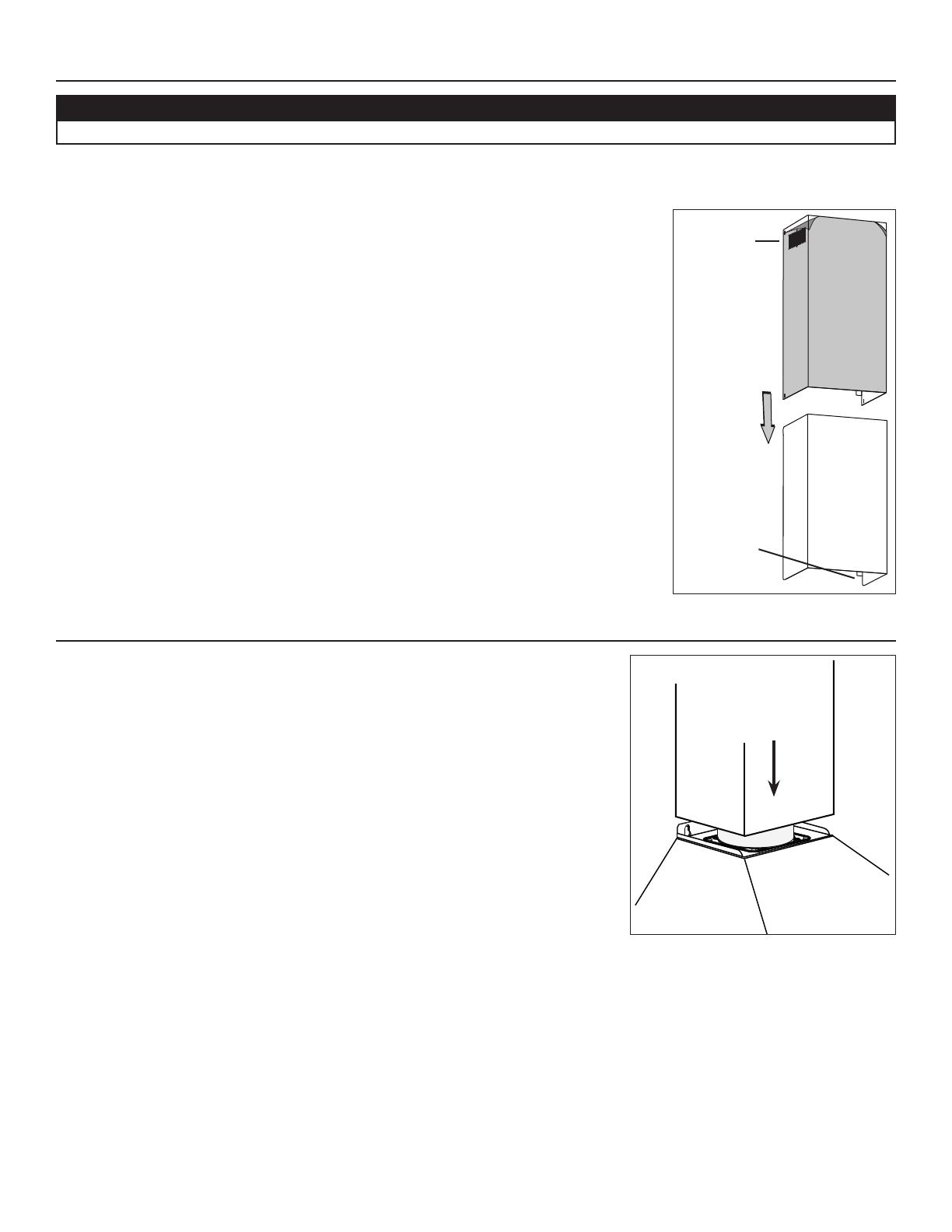
7. INSTALL THE HOOD
1. Align the hood with the center line previously marked on the wall. Gently
lower the hood until it securely engages the screws on the wall.
2. Level the hood and completely tighten the screws on the wall.
3. Secure the hood to the wall by inserting 2 M4 x 38 Phillips 9 mm round head
mounting screws and 2 washers in the lower back of the hood (see back view
at right). Tighten both screws completely.
WARNING
!
BE CAREFUL when installing the decorative flue and hood, they may have sharp edges.
HOLE LOCATIONS
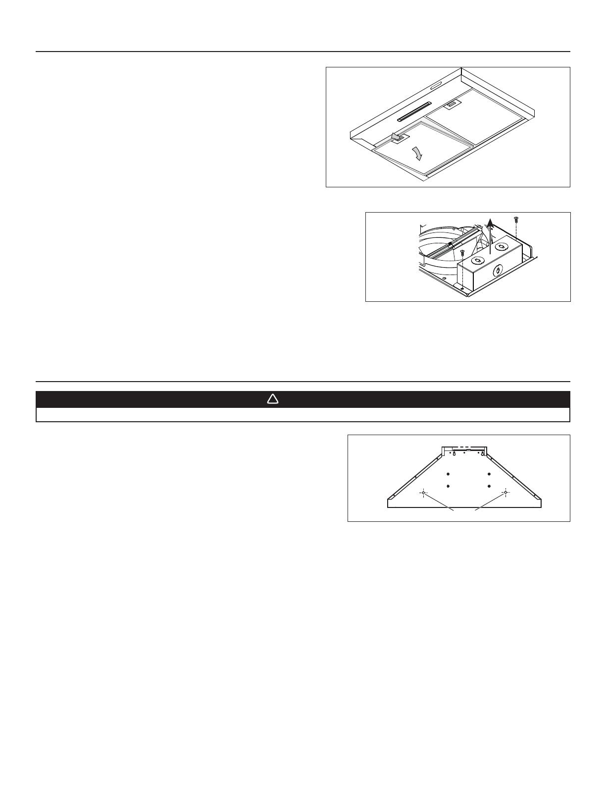
6. REMOVE GREASE FILTER(S)
Lay the back side of the hood flat on a table. Use a piece of cardboard to
avoid damaging the table or the hood.
To remove the grease filter(s), pull down on the metal latch tab and tilt
each filter downward. Set filters aside.
NOTE: There is only one filter on 24-in. width hoods.
HD1148
Detach the junction box cover from the top of the hood by removing both retaining
screws. Set aside the cover and the screws.
HO0296
6
WARNING
!
Risk of electric shock. Electrical wiring must be done by qualified personnel in accordance with all applicable
codes and standards. Before connecting wires, switch power off at service panel and lock service disconnecting
means to prevent power to be switched on accidentally.
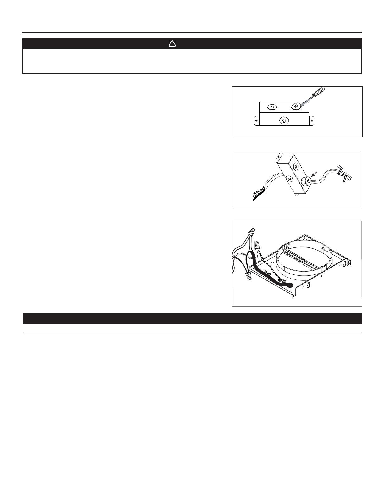
8. CONNECT WIRING
HE0361
Remove a knockout from the junction box cover top previously set aside.
HR0226
Install a UL approved strain relief (not included) on the house power cable at 4"
from the cable end. Run the power cable in the junction box cover opening, then
use the strain relief to secure the house power cable to the junction box cover.
Connect power cable to range hood wiring using included wire connectors.
Connect BLACK to BLACK, WHITE to WHITE and GREEN or BARE WIRE to
GREEN. DO NOT FORGET TO CONNECT THE GROUND.
Reinstall the junction box cover. Make sure all wires are inside the junction box
cover.
HD1157
STRAIN RELIEF
CAUTION
Make sure not to pinch any wire when reinstalling the junction box cover.
7
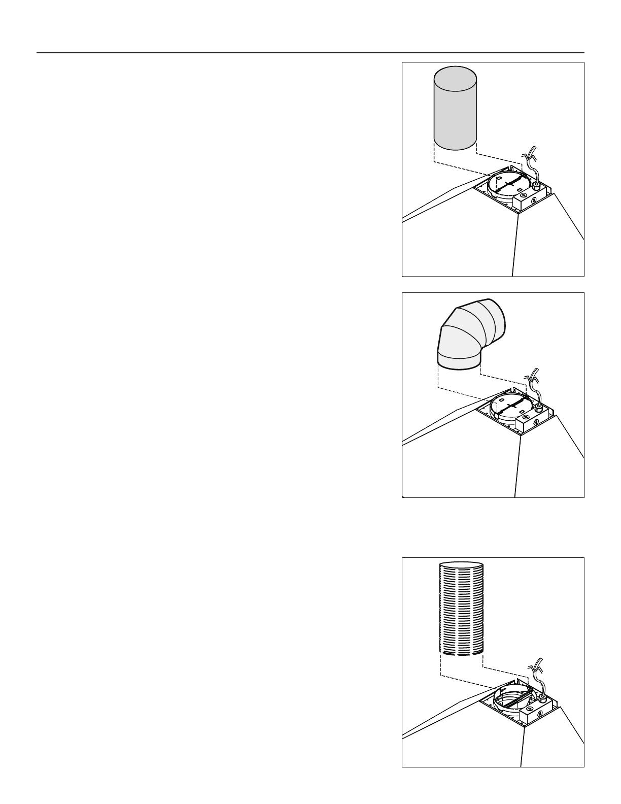
9. DUCT CONNECTION
VERTICALLY DUCTED INSTALLATION:
Slide a 6” round metal duct section over the adapter/damper on the hood up to the roof
cap. Use metal foil duct tape to seal the joint.
HORIZONTALLY DUCTED INSTALLATION:
Measure and install 6” round metal ductwork to wall cap and 90° elbow over duct collar
then install the 90° elbow over the adapter/damper on the hood. Use metal foil duct tape
to seal the joints.
NON-DUCTED INSTALLATION:
Remove the damper flaps. Measure the length of 6” round flexible duct (included in the non-
duct kit) required from the top of the hood to the plenum. Slide the 6” round flexible metal
duct over the adapter on the hood. Use metal foil duct tape to seal the joint.
8
10. PREPARE THE DECORATIVE FLUE
LOUVERS
HO0290
LOWER FLUE
REAR NOTCH
Peel off both corners at the top of the upper flue.
NOTE: For non-ducted installation only, remove enough plastic film to clear the louvers.
Gently slide upper flue inside lower flue, louvers end up.
NOTE: Upper flue can be reversed to hide louvers in some applications depending on installation
heights.
NOTE: Both lower and upper flues are included with the hood, but for ceilings of 9 ft. or more, discard the provided lower and upper flues
and use the optional flue extension, part no. AEEW48SS (stainless steel), AEEW48BLS (black stainless steel) or AEEW48WH
(white) (sold separately).
Remove the upper flue from inside the lower flue. Remove protective plastic film covering the lower
flue only.
11. INSTALL THE DECORATIVE FLUE
Carefully slide in place decorative flue base (notches end first) in the groove on the top of the
hood.
HO0291
CAUTION
DO NOT REMOVE the protective plastic film covering the upper flue yet.
9
DUCTED INSTALLATION:
Slide up the upper flue until it is aligned with its mounting bracket. The bracket must be
inside the flue. Secure the upper flue to its bracket using 2 M4 x 12 Phillips 9 mm
round
head screws.
NOTE: Duct not shown in illustration to ease understanding.
Remove protective plastic film covering the upper flue and the hood.
HO0292
UPPER FLUE MOUNTING BRACKET
FRONT VIEW
UPPER
FLUE
HO0293
NON-DUCTED INSTALLATION:
Slide up the upper flue until it is aligned with the plenum. Secure the upper flue to the
plenum using 2 M4 x 12 Phillips 9 mm round head screws.
Remove protective plastic film covering the upper flue and the hood.
11. INSTALL THE DECORATIVE FLUE (CONTINUED)
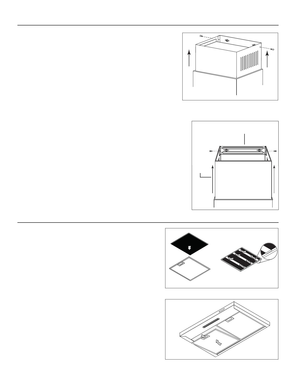
12. REINSTALL GREASE FILTER(S)
ALL INSTALLATIONS:
To reinstall the grease filters, align rear filter tabs with slots in the hood. Pull
down the metal latch tab, push each filter into position and release. Make
sure filters are securely engaged after installation.
HD1149
NON-DUCTED INSTALLATION:
Install a charcoal filter on each aluminum grease filter back (A). Hold the
charcoal filter in place by inserting both ends of the 3 metal strips in each
aluminum grease filter frame (B).
HA0145
AB

10
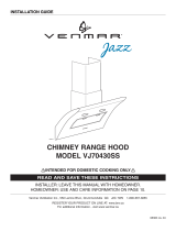
13. OPERATION
Always turn your hood on before you begin cooking to establish an air flow in the kitchen. Let the blower run for a few minutes to clear the
air after you turn off the range. This will help keep the whole kitchen cleaner and brighter.
123
HC0088
1) Blower Speed key + OFF 2) Master ON/OFF key 3) Light Intensities + OFF key
1. BLOWER ON/SPEED INCREASE KEY (DOUBLE FUNCTION KEY):
Press the Blower ON/Speed increase push button to activate the blower at low speed. Press twice for medium speed and once more for
high speed. The LED indicator below the key will light according to the speed level chosen (one LED = low speed, 2 LEDs = medium
speed, 3 LEDs = high speed). Press once more to turn OFF the blower; the LED indicators will then shut off.
2. MASTER ON/OFF KEY
When blower and light are ON, press the Master ON/OFF to turn OFF both blower and light. When blower and light are OFF, press this
key to turn ON the blower to the previous speed setting and turn ON the light at the previous light intensity.
3. LIGHT INTENSITIES + OFF KEY:
Press this key once to turn ON the light on low intensity, one LED indicator will light. Press once more to turn the light on high intensity
(both LED indicators will light). Press another time to turn OFF the light (both LED indicators will then shut off).
14. CARE
Grease Filter(s)
Grease filter(s) should be cleaned frequently. Use a warm dishwashing detergent solution to clean the filter(s). Grease filter(s) are
dishwasher safe.
Clean all-metal filters in the dishwasher using a non-phosphate detergent. Discoloration of the filters may occur if using phosphate
detergents, or as a result of local water conditions - but this will not affect filter performance. This discoloration is not covered by the
warranty. To minimize or prevent discoloration, hand wash filters using a mild detergent.
Non-ducted Filters
Change the non-duct recirculation filters every 6 months. Purchase S99010473 for 24-in and 30-in range hoods or S99010474 for 36-in
range hoods.
Hood Cleaning
Stainless Steel Cleaning:
Avoid when choosing a detergent:
- Any cleaners that contain bleach will attack stainless steel.
- Any products containing: chloride, fluoride, iodide, bromide will deteriorate surfaces rapidly.
- Any combustible products used for cleaning such as acetone, alcohol, ether, benzol, etc., are highly explosive and should never be
used close to a range.
Do:
• Regularly wash with clean cloth or rag soaked with warm water
and mild soap or liquid dish detergent.
• Always clean in the direction of original polish lines.
• Always rinse well with clear water (2 or 3 times) after cleaning.
Wipe dry completely.
• You may also use a specialized household stainless steel
cleaner.
Don’t:
• Use any steel or stainless steel wool or any other scrapers to
remove stubborn dirt.
• Use any harsh or abrasive cleansers.
• Allow dirt to accumulate.
• Let plaster dust or any other construction residues reach the
hood. During construction/renovation, cover the hood to make
sure no dust sticks to stainless steel surface.
Painted finish cleaning:
Clean with warm water and mild detergent only. If discoloration occurs, use a finish polish such as automotive polish. (DO NOT use rough
abrasive cleaner or porcelain cleaner.)

11
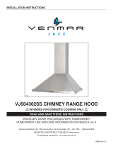
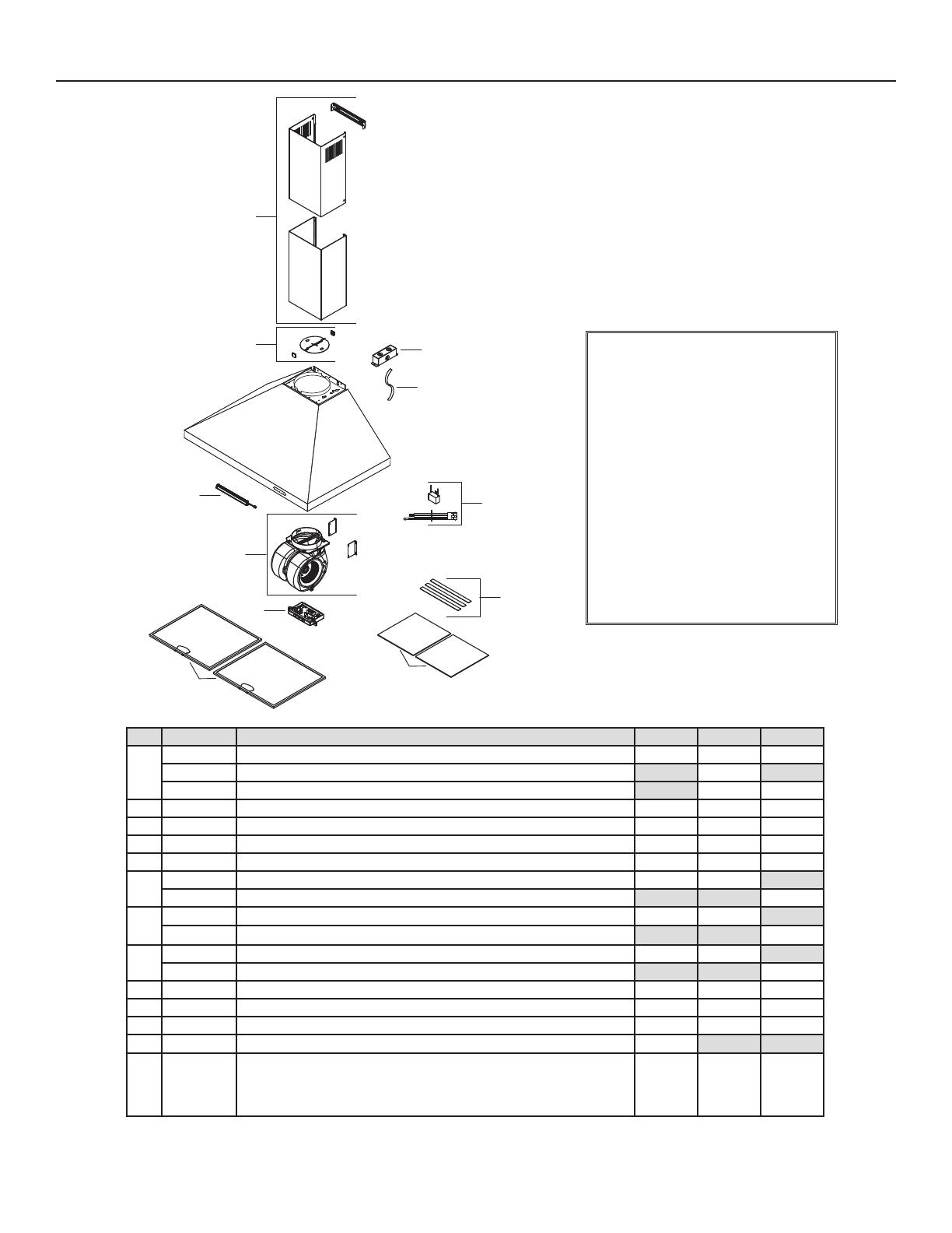
15. REPLACEMENT PARTS
B
C
D
E
F
G
I
J
K
L
HL0455
H
REPLACEMENT PARTS AND REPAIRS
In order to ensure your unit remains in good
working condition, you must use Broan-
NuTone LLC or Venmar Ventilation ULC
genuine replacement parts only. Broan-NuTone
LLC or Venmar Ventilation ULC genuine
replacement parts are specially designed for
each unit and are manufactured to comply
with all the applicable certification standards
and maintain a high standard of safety. Any
third party replacement part used may cause
serious damage and drastically reduce the
performance level of your unit, which will result
in premature failing. Broan-NuTone LLC and
Venmar Ventilation ULC recommend to contact
a certified service depot for all replacement
parts and repairs.
KEY NO.PART NO.DESCRIPTION 24" 30" 36"
1
S97021438 D
ECORATIVE UPPER AND LOWER FLUES (STAINLESS STEEL) WITH BRACKET 111
S97021439 DECORATIVE UPPER AND LOWER FLUES (WHITE)1
S97021440 DECORATIVE UPPER AND LOWER FLUES (BLACK STAINLESS STEEL)11
2 S99527461 DAMPER ASSEMBLY 111
3 S99010479 LED MODULE 111
4 S97021444 M
OTOR AND BLOWER ASSEMBLY 111
5 S97021443 ELECTRONIC BOARD 111
6
S99010476 ALUMINUM GREASE FILTERS (SET OF 2) 1 1
S99010477 ALUMINUM GREASE FILTERS (SET OF 2) 1
7
S99010473 NON-DUCT RECIRCULATION FILTERS (SET OF 2) (METAL STRIPS NOT INCLUDED)11
S99010474 NON-DUCT RECIRCULATION FILTERS (SET OF 2) (METAL STRIPS NOT INCLUDED)1
8
S99010480 M
ETAL STRIPS FOR NON-DUCT RECIRCULATION FILTERS S99010473 (SET OF 3) 1 2
S99010481 M
ETAL STRIPS FOR NON-DUCT RECIRCULATION FILTERS S99010474 (SET OF 3) 2
9 S99271686 CAPACITOR AND MAIN HARNESS ASSEMBLY 111
10 S99271684 POWER CABLE 111
11 S99840026 J
UNCTION BOX 111
* S99064948 FILTER FILLER (SET OF 2) 1
* S97021436
PARTS BAG INCLUDING: 6 M4 X 38 PHILLIPS 9 MM ROUND HEAD MOUNTING SCREWS,
2 M4 X 12 PHILLIPS 9 MM ROUND HEAD SCREWS, 2 WASHERS, 3 WIRE CONNECTORS
AND 1 UPPER FLUE MOUNTING BRACKET
111
* NOT SHOWN.

12
Limited Warranty
Warranty Period and Exclusions: Broan-NuTone LLC and Venmar Ventilation ULC (either being the “Company”) warrants to the original
consumer purchaser of its product (“you”) that the product (the “Product”) will be free from material defects in the Product or its workmanship for a
period of one (1) year from the date of original purchase (or such longer period as may be required by applicable law). The limited warranty period
for any replacement parts provided by the Company and for any Products repaired or replaced under this limited warranty shall be the remainder
of the original warranty period (or such longer period as may be required by applicable law).
This warranty does not cover fluorescent lamp starters, tubes, halogen and incandescent bulbs, fuses, filters, ducts, roof caps, wall caps and
other accessories for ducting that may be purchased separately and installed with the Product. This warranty also does not cover (a) normal
maintenance and service, (b) normal wear and tear, (c) any Products or parts which have been subject to misuse, abuse, abnormal usage,
negligence, accident, improper or insufficient maintenance, storage or repair (other than repair by the Company), (d) damage caused by faulty
installation, or installation or use contrary to recommendations or instructions, (e) any Product that has been moved from its original point of
installation, (f) damage caused by environmental or natural elements, (g) damage in transit, (h) natural wear of finish, (i) Products in commercial
or nonresidential use, or (j) damage caused by fire, flood or other act of God or (k) Products with altered, defaced or removed serial numbers. This
warranty covers only Products sold to original consumers in the United States and Canada by the Company or its U.S. and Canadian distributors
authorized by the Company.
This warranty supersedes all prior warranties and, subject to applicable law, is not transferable from the original consumer purchaser.
No Other Warranties: This Limited Warranty contains the Company’s sole obligation and your sole remedy for defective products. The foregoing
warranties are exclusive and in lieu of any other warranties and conditions, express or implied. THE COMPANY DISCLAIMS AND EXCLUDES
ALL OTHER EXPRESS WARRANTIES AND CONDITIONS, AND DISCLAIMS AND EXCLUDES ALL WARRANTIES AND CONDITIONS
IMPLIED BY LAW, INCLUDING WITHOUT LIMITATION THOSE OF MERCHANTABILITY AND FITNESS FOR A PARTICULAR PURPOSE.
To the extent that applicable law prohibits the exclusion of implied warranties or conditions, the duration of any applicable implied warranty or
condition is limited to the period specified for the express warranty above. Some jurisdictions do not allow limitations on how long an implied
warranty lasts, so the above limitation may not apply to you. Any oral or written description of the Product is for the sole purpose of identifying it
and shall not be construed as an express warranty.
Whenever possible, each provision of this Limited Warranty shall be interpreted in such manner as to be effective and valid under applicable law,
but if any provision is held to be prohibited or invalid, such provision shall be ineffective only to the extent of such prohibition or invalidity, without
invalidating the remainder of such provision or the other remaining provisions of the Limited Warranty.
Remedy: During the applicable limited warranty period, the Company will, at its option, provide replacement parts for, or repair or replace, without
charge, any Product or part thereof, to the extent the Company finds it to be covered by and in breach of this limited warranty under normal use
and service. The Company will ship the repaired or replaced Product or replacement parts to you at no charge. You are responsible for all costs
for removal, reinstallation and shipping, insurance or other freight charges incurred in the shipment of the Product or part to the Company. If you
must send the Product or part to the Company, as instructed by the Company, you must properly pack the Product or part—the Company is not
responsible for damage in transit. The Company reserves the right to utilize reconditioned, refurbished, repaired or remanufactured Products
or parts in the warranty repair or replacement process. Such Products and parts will be comparable in function and performance to an original
Product or part and warranted for the remainder of the original warranty period (or such longer period as may be required by applicable law).
Company reserves the right, in its sole discretion, to refund the money actually paid by you for the Product in lieu of repair or replacement. If
the Product or component is no longer available, replacement may be made with a similar product of equal or greater value, at Company’s sole
discretion. This is your sole and exclusive remedy for breach of this limited warranty.
Exclusion of Damages: THE COMPANY’S OBLIGATION TO PROVIDE REPLACEMENT PARTS, OR REPAIR, REPLACE OR REFUND, AT
THE COMPANY’S OPTION, SHALL BE YOUR SOLE AND EXCLUSIVE REMEDY UNDER THIS LIMITED WARRANTY AND THE COMPANY’S
SOLE AND EXCLUSIVE OBLIGATION. THE COMPANY SHALL NOT BE LIABLE FOR INCIDENTAL, INDIRECT, CONSEQUENTIAL OR
SPECIAL DAMAGES ARISING OUT OF OR IN CONNECTION WITH THE PRODUCT, ITS USE OR PERFORMANCE. Incidental damages
include but are not limited to such damages as loss of time and loss of use. Consequential damages include but are not limited to the cost of
repairing or replacing other property which was damaged if the Product does not work properly.
THE COMPANY SHALL NOT BE LIABLE TO YOU, OR TO ANYONE CLAIMING UNDER YOU, FOR ANY OTHER OBLIGATIONS OR
LIABILITIES, INCLUDING, BUT NOT LIMITED TO, OBLIGATIONS OR LIABILITIES ARISING OUT OF BREACH OF CONTRACT OR
WARRANTY, NEGLIGENCE OR OTHER TORT OR ANY THEORY OF STRICT LIABILITY, WITH RESPECT TO THE PRODUCT OR THE
COMPANY’S ACTS OR OMISSIONS OR OTHERWISE.
Some jurisdictions do not allow the exclusion or limitation of incidental or consequential damages, so the above limitation or exclusion may not
apply to you. This warranty gives you specific legal rights, and you may also have other rights, which vary from jurisdiction to jurisdiction. The
disclaimers, exclusions, and limitations of liability under this warranty will not apply to the extent prohibited by applicable law.
This warranty covers only replacement or repair of defective Products or parts thereof at the Company’s main facility and does not include the cost
of field service travel and living expenses.
Any assistance the Company provides to or procures for you outside the terms, limitations or exclusions of this limited warranty will not constitute
a waiver of such terms, limitations or exclusions, nor will such assistance extend or revive the warranty.
The Company will not reimburse you for any expenses incurred by you in repairing or replacing any defective Product, except for those incurred
with the Company’s prior written permission.
How to Obtain Warranty Service: To qualify for warranty service, you must (a) notify the Company at the address or telephone number stated
below within seven (7) days of discovering the covered defect, (b) give the model number and part identification and (c) describe the nature of any
defect in the Product or part. At the time of requesting warranty service, you must present evidence of the original purchase date. If you cannot
provide a copy of the original written limited warranty, then the terms of the Company’s most current written limited warranty for your particular
product will control. The most current limited written warranties for the Company’s products can be found at www.broan.com and www.broan.ca.
Broan-NuTone LLC 926 West State Street, Hartford, WI 53027 www.broan.com 800-637-1453
Venmar Ventilation ULC, 550 Lemire Blvd., Drummondville, Québec, Canada J2C 7W9 www.broan.ca 1-877-896-1119
16. WARRANTY
11
15. PIEZAS DE RECAMBIO
REPUESTOS Y REPARACIONES
Para que el aparato esté en buenas
condiciones, use sólo repuestos genuinos
Broan-NuTone LLC o Venmar Ventilation
ULC. Los repuestos genuinos Broan-
NuTone LLC o Venmar Ventilation ULC
están diseñados especialmente para
cada unidad y han sido fabricados para
responder a las normas de certificación
aplicables y mantener un alto nivel
de seguridad. Los repuestos de otros
fabricantes pueden dañar seriamente el
aparato y reducir drásticamente su nivel de
rendimiento, lo cual podría causar una falla
prematura. Broan-NuTone LLC y Venmar
Ventilation ULC recomiendan comunicar
con un centro de servicios autorizado para
todos los repuestos y reparaciones.
N. N. DE PIEZA DESCRIPCIÓN 24 PULG. 30 PULG. 36 PULG.
1
S97021438 C
HIMENEA DECORATIVA (SUPERIOR Y INFERIOR) (ACERO INOXIDABLE) CON SOPORTE 111
S97021439 CHIMENEA DECORATIVA (SUPERIOR Y INFERIOR) (BLANCO)1
S97021440 C
HIMENEA DECORATIVA (SUPERIOR Y INFERIOR) (ACERO INOXIDABLE NEGRO)11
2 S99527461 C
ONJUNTO DE LA COMPUERTA 111
3 S99010479 MóDULO LED 1 1 1
4 S97021444 CONJUNTO DE MOTOR Y VENTILADOR 111
5 S97021443 TARJETA ELECTRÓNICA 111
6
S99010476 FILTROS DE GRASA DE ALUMINIO (JUNTO DE 2) 1 1
S99010477 FILTROS DE GRASA DE ALUMINIO (JUNTO DE 2) 1
7
S99010473
F
ILTROS DE RECIRCULACIÓN (JUNTO DE 2) (TIRAS DE METAL NO INCLUIDAS)
11
S99010474
FILTROS DE RECIRCULACIÓN (JUNTO DE 2) (TIRAS DE METAL NO INCLUIDAS)
1
8
S99010480 T
IRAS DE METAL POR FILTROS DE RECIRCULACIÓN S99010473 (JUNTO DE 3) 1 2
S99010481 TIRAS DE METAL POR FILTROS DE RECIRCULACIÓN S99010474 (JUNTO DE 3) 2
9 S99271686 CONJUNTO DEL CONDENSADOR Y ARNES DE HILOS 111
10 S99271684 C
ABLE DE ALIMENTACIÓN 111
11 S99840026 C
AJA DE CONEXIONES 111
* S99064948
R
ELLENO DE FILTRO (JUNTO DE 2) POR UNA CAMPANA DE 24” DE ANCHO
1
* S97021436
B
OLSA DE PIEZA: 6 TORNILLOS DE MONTAJE M4 X 38 PHILLIPS DE CABEZA REDONDA
9 MM, 2 TORNILLOS DE MONTAJE M4 X 12 PHILLIPS DE CABEZA REDONDA 9 MM,
2 ARANDELAS, 3 CONECTADORES Y SOPORTE DE MONTAJE DE LA PA RT E SUPERIOR
DE LA CHIMENEA
111
* NO SE MUESTRA.
B
C
D
E
F
G
I
J
K
L
HL0455
H
/