Page is loading ...

MODELS BWS1304SS • BWS1304BLS •
BWS2304SS • BWS2304BLS
Page 1
READ AND SAVE THESE INSTRUCTIONS
CHIMNEY
RANGE HOOD
!
INTENDED FOR DOMESTIC COOKING ONLY.
!
TO REDUCE THE RISK OF FIRE, ELECTRIC SHOCK, OR
INJURY TO PERSON(S) OBSERVE THE FOLLOWING:
1. Use this unit only in the manner intended by the manufacturer.
If you have questions, contact the manufacturer at the
address or telephone number listed in the warranty.
2. Before servicing or cleaning unit, switch power off at service
panel and lock service disconnecting means to prevent
power from being switch on accidentally. When the service
disconnecting means cannot be locked, securely fasten a
prominent warning device, such as a tag, to the service
panel.
3. Installation work and electrical wiring must be done by
qualified personnel in accordance with all applicable codes
and standards, including fire-rated construction codes and
standards.
4. Sufficient air is needed for proper combustion and exhausting
of gases through the flue (chimney) of fuel burning equipment
to prevent backdrafting. Follow the heating equipment
manufacturer’s guidelines and safety standards such as
those published by the National Fire Protection Association
(NFPA), the American Society for Heating, Refrigeration
and Air Conditioning Engineers (ASHRAE) and the local
code authorities.
5. This product may have sharp edges. Be carefule to avoid
cuts and abrasions during installation or cleaning.
6. When cutting or drilling into wall or ceiling, do not damage
electrical wiring and other hidden utilities.
7. Ducted fans must always be vented to the outdoors.
8. Do not use this unit with any other solid-state speed control
device.
9. Use only metal ductwork.
10. This unit must be grounded.
TO REDUCE THE RISK OF A RANGE TOP GREASE FIRE:
a) Never leave surface units unattended at high settings.
Boilovers cause smoking and greasy spillovers that may
ignite. Heat oils slowly on low or medium settings.
b) Always turn hood ON when cooking at high heat or when
cooking flaming foods (i.e. Crêpes Suzette, Cherries Jubilee,
Peppercorn Beef Flambé).
c) Clean ventilating fans frequently. Grease should not be
allowed to accumulate on fan or filters.
d) Use proper pan size. Always use cookware appropriate for
the size of the surface element.
WARNING
TO REDUCE THE RISK OF INJURY TO PERSON(S) IN THE
EVENT OF A RANGE TOP GREASE FIRE, OBSERVE THE
FOLLOWING*:
1. SMOTHER FLAMES with a close-fitting lid, cookie sheet, or
metal tray, then turn off the burner. BE CAREFUL TO PREVENT
BURNS. IF THE FLAMES DO NOT GO OUT IMMEDIATELY,
EVACUATE AND CALL THE FIRE DEPARTMENT.
2. NEVER PICK UP A FLAMING PAN – You may be burned.
3. DO NOT USE WATER, including wet dishcloths or towels –
This could cause a violent steam explosion.
4. Use an extinguisher ONLY if:
A. You know you have a Class ABC extinguisher and you
know how to operate it.
B. The fire is small and contained in the area where it
started.
C. The fire department has been called.
D. You can fight the fire with your back to an exit.
* Based on “Kitchen Fire Safety Tips” published by NFPA.
CAUTION
!
1. For indoor use only.
2. For general ventilating use only. Do not use to exhaust
hazardous or explosive materials and vapors.
3. To avoid motor bearing damage and noisy and/or
unbalanced impeller, keep drywall spray, construction dust,
etc. off power unit.
4. Do not use over cooking equipment greater than 60,000
BTU/hr. as the blower motor will shut down intermittently.
5. Your hood motor has a thermal overload which will
automatically shut off the motor if it becomes overheated.
The motor will restart when it cools down. If the motor
continues to shut off and restart, have the hood serviced.
6. The bottom of the hood MUST NOT BE LESS than 24” and
at a maximum of
36” above cooktop for best capture of
cooking impurities.
7. Two installers are recommended because of the size of
this hood.
8. To reduce risk of fire and to properly exhaust air, be sure
to duct air outside. Do not exhaust air into spaces within
walls or ceilings or into attics, crawl spaces, or garages.
9. Be careful when installing the decorative flue and hood,
they may have sharp edges.
10. Please read specification label on product for further
information and requirements.
INSTALLER: LEAVE THIS GUIDE WITH THE HOMEOWNER.
HOMEOWNER: OPERATION AND MAINTENANCE INFORMATION ON PAGE 2.
WARNING
To register this product visit:
www.broan.com or
www.broan.ca

MODELS BWS1304SS • BWS1304BLS •
BWS2304SS • BWS2304BLS
Page 2
CLEANING & MAINTENANCE
Proper maintenance of the Range Hood will assure proper
performance of the unit.
MOTOR
The motor is permanently lubricated and never needs oiling. If
the motor bearings make excessive or unusual noise, replace
the blower with the exact service blower.
GREASE FILTERS
The grease filters should be cleaned frequently. Use a warm
dishwashing detergent solution. Grease filters are dishwasher
safe.
Clean all-metal filters in the dishwasher using a non-phosphate
detergent. Discoloration of the filters may occur if using phosphate
detergents, or as a result of local water conditions - but this will
not affect filter performance. This discoloration is not covered by
the warranty.
Remove grease filters by pulling down on the metal latch tab. This
will disengage the filters from the hood. Tilt the filters downward
and remove.
NON-DUCTED RECIRCULATION FILTERS
The non-ducted recirculation filters should be changed every
6 months. Replace more often if your cooking style generates
extra grease, such as frying and wok cooking. Turn the filter
mounting tabs to remove filter and replace.
STAINLESS STEEL CLEANING
DO:
• Regularly wash with clean cloth or rag soaked with warm water
and mild soap or liquid dish detergent.
• Always clean in the direction of original polish lines.
• Always rinse well with clear water (2 or 3 times) after cleaning.
Wipe dry completely.
• You may also use a specialized household stainless steel
cleaner.
DON’T:
• Use any steel or stainless steel wool or any other scrapers to
remove stubborn dirt.
• Use any harsh or abrasive cleansers.
• Allow dirt to accumulate.
• Let plaster dust or any other construction residues reach the
hood. During construction/renovation, cover the range hood to
make sure no dust sticks to the stainless steel surface.
Avoid: When choosing a detergent
• Any cleaners that contain bleach will attack stainless steel
• Any products containing: chloride, fluoride, iodide, bromide
will deteriorate surfaces rapidly.
• Any combustible products used for cleaning such as acetone,
alcohol, ether, benzol, etc., are highly explosive and should
never be used close to a range.
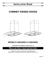
OPERATION
The hood is operated using the push buttons on the front panel.
Push the light button to turn the lights on and off.
Push the blower controls to select low, medium, or high blower
speed (for each speed selected, its indicating light will beam).
Press on the current blower speed another time to stop it.
While the blower is activated, press the 5-minute delay button
once (its indicating light will beam) to get the hood running for
5 minutes and then turn off automatically.
When the 5-minute delay is activated, changing the blower
speed will cancel the 5-minute delay function.
To cancel the delay off function before the end of the 5-minute
cycle, press again on 5-minute delay push button or select an
other blower speed.
HC0095
LIGHT
ON/OFF
LOW MED. HIGH
BLOWER CONTROLS
5-MINUTE
DELAY

MODELS BWS1304SS • BWS1304BLS •
BWS2304SS • BWS2304BLS
Page 3
INSTALL THE DUCTWORK
(Ducted Hoods Only)
1. Decide where
the ductwork
will run
between the
hood and the
outside.
2. A straight, short
duct run will
allow the hood
to perform most
efficiently.
3. Long duct
runs, elbows
and transitions
will reduce the
performance of
the hood. Use as few of them as possible. Larger ducting
may be required for best performance with longer duct runs.
4. Install wall cap or roof cap. Connect round metal ductwork
to cap and work back towards the hood location. Use duct
tape to seal the joints between ductwork sections.
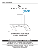
MEASURE THE INSTALLATION
The minimum hood distance above cooktop MUST NOT BE
LESS than 24”.
A maximum of 36” above cooktop is highly recommended for
best capture of cooking impurities.
Distances over 36” are at the installer and users discretion;
providing that the ceiling height permits.
6"
ROUND DUCT
ROOF CAP
ROUND
ELBOW
24" MIN. ABOVE
COOKING SURFACE
WALL
CAP
HOOD
DECORATIVE
FLUE
10-1/2”
WALL CAP
24” - 36” ABOVE
COOKING SURFACE
HOOD
DECORATIVE FLUE
ROOF CAP
6” ROUND DUCT
ROUND ELBOW
11-7/8”
TO CENTER OF
BRACKET HOLES
HOOD
MOUNTING
BRACKET
3-3/8”
DUCT
CENTER
LINE
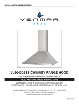
PREPARE THE HOOD
Unpack hood and check contents. You should receive:
1 - Hood
1 - Decorative Flue Assembly
2 - Damper Flaps
1 - Lower Flue Mounting Bracket
1 - Upper Flue Mounting Bracket
1 - Hood Mounting Bracket
2 - Aluminum Grease Filters (BWS1 series, included
packaged in a cardboard box)
2 - Hybrid Baffle Filters (BWS2 series, included packaged in a
cardboard box)
1 - Installation Manual
1 - Parts Bag containing:
4 - Mounting Screws (no. 8 x 3/8” Pan Head)
7 - Mounting Screws (no. 8 x 1-1/2” Flat Head)
7 - Drywall Anchors
2 - Washers
7 MOUNTING
SCREWS
(no. 8 x 1½”
Flat Head)
7 DRYWALL
ANCHORS
4 MOUNTING
SCREWS
(no. 8 x 3/8”
Pan Head)
DECORATIVE FLUE
2 WASHERS
UPPER
FLUE MOUNTING
BRACKET
HOOD
MOUNTING
BRACKET
LOWER
FLUE MOUNTING
BRACKET
DAMPER
FLAPS

MODELS BWS1304SS • BWS1304BLS •
BWS2304SS • BWS2304BLS
Page 4
PREPARE THE HOOD (CONT’D)
For ducted installation only:
Install both damper flaps inside the blower exhaust opening,
ensuring the pins are top oriented. See illustration below.
PINS ON TOP
1. GROUNDING INSTRUCTIONS
This appliance must be grounded. In the event of an electrical
short circuit, grounding reduces the risk of electric shock
by providing an escape wire for the electric current. This
appliance is equipped with a cord having a grounding wire
with a grounding plug. The plug must be plugged into an
outlet that is properly installed and grounded.
NOTE:
A recessed “clock” outlet is recommended.
2. Position the electrical outlet within the space covered by
the decorative flue and where it will not interfere with the
round duct. Make sure the outlet does not interfere with the
mounting bracket fastening area, ductwork, or where the
decorative flue touches the wall.
INSTALL THE WIRING
4”
21”
12”
LOCATE
ELECTRICAL
OUTLET
WITHIN THESE
AREAS.
(Verify location
will not interfere
with duct,
mounting
brackets,
and flue.)

MODELS BWS1304SS • BWS1304BLS •
BWS2304SS • BWS2304BLS
Page 5
INSTALL THE HOOD MOUNTING BRACKET
C
L
1. Construct wood wall framing that is flush with
interior surface of wall studs.
Make sure:
a) the framing is centered over installation
location.
b) the height of the framing will allow the
mounting bracket to be secured to the framing
within the dimensions shown.
2. After wall surface is finished, carefully center and
level the hood mounting bracket and secure it
to wall framing with (3) no. 8 x 1½” mounting
screws. Tighten the screws completely.
NOTE: Do not use drywall anchors.
10⁄16”
41
7
/8” = bottom of hood 30” above cooktop
5⁄32”
FRAMING BEHIND
DRYWALL
1
9
⁄16”
WALL STUDS
NOTE:
Minimum hood distance above cooktop must not be less than 24”.
Distances over 36” above the cooktop are at the installer’s and user’s discretion - providing that ceiling height and flue length permit.
MOUNTING BRACKET LOCATION
(ABOVE 36” HIGH COOKTOP)
NOTE:
On 8-ft. ceilings
Hood distance above cooktop is:
Minimum 24”, Maximum 36” (for both ducted and
non-ducted discharge
On 9-ft. ceilings
Hood distance above cooktop is:
Minimum 29”, Maximum 36” (for both ducted and
non-ducted discharge)
On 10-ft. ceilings
Hood distance above cooktop is:
Minimum 29”, Maximum 36” (for both ducted and
non-ducted discharge).
NOTE: 10-ft. ceilings require 10-ft. Flue
Extension, model AEBWS (stainless steel) or
model AEBWSBLS (black stainless steel) for
ducted or non-ducted installations
(purchase separately).
CEILING
HEIGHT
DUCT
METHOD
HOOD DISTANCE ABOVE 36” COOK TOP
24” 25” 26” 27” 28” 29” 30” 31” 32” 33” 34” 35” 36”
MOUNTING BRACKET LOCATION ABOVE 36” HIGH COOK TOP
8 FEET
DUCTED
35-7/8” 36-7/8” 37-7/8” 38-7/8” 39-7/8” 40-7/8” 41-7/8” 42-7/8” 43-7/8” 44-7/8” 45-7/8”
--- ---
NON-DUCTED
35-7/8” 36-7/8” 37-7/8” 38-7/8” 39-7/8” 40-7/8” 41-7/8” 42-7/8”
43-7/8” 44-7/8” 45-7/8”
--- ---
9 FEET
DUCTED --- --- --- --- ---
40-7/8” 41-7/8” 42-7/8” 43-7/8” 44-7/8” 45-7/8”
46-7/8” 47-7/8”
NON-DUCTED --- --- --- --- ---
40-7/8” 41-7/8” 42-7/8”
43-7/8” 44-7/8” 45-7/8”
46-7/8” 47-7/8”
10 FEET
DUCTED --- --- --- --- ---
40-7/8” 41-7/8” 42-7/8” 43-7/8” 44-7/8” 45-7/8”
46-7/8” 47-7/8”
NON-DUCTED --- --- --- --- ---
40-7/8” 41-7/8” 42-7/8”
43-7/8” 44-7/8” 45-7/8”
46-7/8” 47-7/8”

MODELS BWS1304SS • BWS1304BLS •
BWS2304SS • BWS2304BLS
Page 6
INSTALL UPPER FLUE MOUNTING
BRACKET
1. If a framing member is not present, drill two 5/16” diameter
holes where shown. Insert drywall anchors into the holes.
2. Center the bracket over the hood location and flush with the
ceiling. Make sure that the slots of the upper flue bracket are
at the bottom. Secure the upper flue bracket to the wall using
(2) no. 8 x 1½” mounting screws.
3. Tighten the screws completely. Make sure that the bracket
is tight against the wall.
C
L
Flush with
the ceiling
Center of
installation
Upper flue mounting
bracket slots
C
L
7/8”
3⁄16”
1”
Recommended
distance between
screw holes
Ceiling
Ø 5/16” TYP.
Ceiling
Center of installation
INSTALL THE HOOD
(Horizontally Ducted Hoods Only)
1. DO NOT REMOVE the protective plastic film covering the
decorative flue and the hood at this time.
2. Lay the back side of the hood flat on a table. Use a piece of
cardboard to avoid damaging the table or the hood.
3. Remove the grease filters by pulling down the metal latch
tab and tilting filters downward to remove.
4. Carefully rotate hood upright.
INSIDE BACK OF HOOD
MOTOR/BLOWER
ASSEMBLY
HOLES LOCATION
SIDE VIEW
Ø 5/16” TYP.
5. To make sure there will be adequate clearance between top
of hood and lower flue mounting bracket for ductwork: Elbow
must be located below lower flue mounting bracket.
6. Align the hood and center it above the hood mounting
bracket. Gently lower the hood until it securely engages the
bracket.
7. With the hood hanging in place, drill through both holes
located in the inside lower back of hood using a 5/16” drill
bit. Insert the included drywall anchors into the drilled holes
(one for each hole). Install (2) washers and (2) no. 8 x 1½”
mounting screws through the hood back and into the drywall
anchors. Verify that the hood is centered and leveled.
Tighten all screws completely.
8. Reinstall grease filters by aligning rear filter tabs with slots
in the hood. Pull down the metal latch tab, push filter into
position and release. Make sure filters are securely engaged
after installation.
11¾”
MAX.
LOWER FLUE
MOUNTING BRACKET

MODELS BWS1304SS • BWS1304BLS •
BWS2304SS • BWS2304BLS
Page 7
LOWER FLUE MOUNTING BRACKET
LOWER
FLUE
NOTE: 10-ft. ceilings require 10-ft. Flue Extension Model
AEBWS (stainless steel) or AEBWSBLS (black stainless
steel) (purchase separately). Discard the upper flue
supplied with your hood and replace it with the appropriate
flue extension.
11. Remove the upper flue from inside the lower flue. Install
the lower flue bracket to the lower flue using (2) flue
bracket screws (no. 8 x 3/8”). Make sure that the bracket is
positioned inside of the lower flue flanges - with the slots on
top. Carefully replace the upper flue inside the lower flue.
Remove protective plastic film covering the lower flue only.
12. Carefully place both flues into the recessed area of hood
top.
13. Slide the upper flue upward until it is aligned with its upper
flue mounting bracket. The bracket should be inside the flue.
Secure the upper flue to the upper flue mounting bracket
using (2) no. 8 x 3/8” mounting screws.
14. Remove protective plastic film covering the upper flue and
the hood.
UPPER
FLUE
UPPER FLUE MOUNTING BRACKET
6” ROUND
DUCT ELBOW
9. Measure and install 6” round steel ductwork to roof cap or
wall cap and 90
o
elbow over the blower exhaust opening on
top of hood. Use duct tape to make all joints secure and air
tight.
10. Plug hood power cord into the outlet.
INSTALL THE HOOD
(Vertically Ducted Hoods Only)
1. DO NOT REMOVE the protective plastic film covering the
decorative flue and the hood at this time.
2. Lay the back side of the hood flat on a table. Use a piece of
cardboard to avoid damaging the table or the hood.
3. Remove the grease filters by pulling down the metal latch
tab and tilting filters downward to remove.
4. Carefully rotate hood upright.
LOWER FLUE MOUNTING BRACKET
LOWER
FLUE
NOTE: 10-ft. ceilings require 10-ft. Flue Extension Model
AEBWS (stainless steel) or AEBWSBLS (black stainless
steel) (purchase separately). Discard the upper flue
supplied with your hood and replace it with the appropriate
flue extension.
5. Remove the upper flue from inside the lower flue. Install
the lower flue bracket to the lower flue using (2) flue
bracket screws (no. 8 x 3/8”). Make sure that the bracket is
positioned inside of the lower flue flanges - with the slots on
top. Carefully replace the upper flue inside the lower flue.
Remove protective plastic film covering the lower flue only.
6. Carefully place both flues into the recessed area of hood top.

MODELS BWS1304SS • BWS1304BLS •
BWS2304SS • BWS2304BLS
Page 8
INSTALL THE HOOD
(Non-Ducted Hoods Only)
7. Measure and install 6” round steel ductwork to the blower
exhaust opening on top of hood. Use duct tape to make all
joints secure and air tight.
8. Hold hood up close to wall mounting location and plug
power cord into wall outlet.
9. Align the hood and center it above the hood mounting
bracket. Make sure ductwork on hood lines up and attaches
to ductwork in ceiling. Gently lower the hood until it securely
engages the bracket.
10. Use duct tape to make all joints secure and air tight.
INSIDE BACK OF HOOD
MOTOR/BLOWER
ASSEMBLY
HOLES LOCATION
SIDE VIEW
Ø 5/16” TYP.
11. With the hood hanging in place, drill through both holes
located in the inside lower back of hood using a 5/16” drill
bit. Insert the included drywall anchors into the drilled holes
(one for each hole). Install (2) washers and (2) no. 8 x 1½”
mounting screws through the hood back and into the drywall
anchors. Verify that the hood is centered and leveled. Tighten
all screws completely.
12. Reinstall grease filters by aligning rear filter tabs with slots
in the hood. Pull down the metal latch tab, push filter into
position and release. Make sure filters are securely engaged
after installation.
13. Slide the upper flue upward until it is aligned with its upper
flue mounting bracket. The bracket should be inside the flue.
Secure the upper flue to the upper flue mounting bracket
using (2) no. 8 x 3/8” mounting screws.
14. Remove protective plastic film covering the upper flue and
the hood.
UPPER
FLUE
UPPER FLUE MOUNTING BRACKET
DUCT LENGTH
DECORATIVE
FLUE
6” ROUND
STEEL DUCT
NOTE: Non-ducted installations require Non-Duct Kit,
Model ARKBWS (purchase separately).
1. CAUTION: Use only flexible duct provided.
2. Do not remove the protective plastic film covering the
decorative flue and the hood at this time.
3. Lay the back side of the hood flat on a table. Use a piece
of cardboard to avoid damaging the table or the hood.
NON-DUCT KIT MODEL ARKBWS CONTENTS
NON-DUCT
PLENUM
2 TIE
WRAPS
FLEXIBLE DUCT
NON-DUCTED
RECIRCULATION
FILTERS
NON-DUCT PLENUM
COLLAR
8 MOUNTING
SCREWS
(ST4 x 8
Round Head)

MODELS BWS1304SS • BWS1304BLS •
BWS2304SS • BWS2304BLS
Page 9
length of the
extended flex
duct.
7. Attach
aluminum
flexible duct
to the blower
discharge
opening with a
tie wrap.
8. Attach flexible
duct to non-duct
plenum collar
and secure with
tie wrap. Tape
all joints with duct tape.
NOTE: 10-ft. ceilings require 10-ft. Flue Extension Model
AEBWS (stainless steel) or AEBWSBLS (black stainless
steel) (purchase separately). Discard the upper flue
supplied with your hood and replace it with the appropriate
flue extension.
9. Remove the upper flue from inside the lower flue. Install
the lower flue bracket to the lower flue using (2) flue
bracket screws (no. 8 x 3/8”). Make sure that the bracket is
positioned inside of the lower flue flanges - with the slots on
top. Carefully replace the upper flue inside the lower flue.
Remove protective plastic film covering the lower flue only.
10. Carefully place both flues into the recessed area of hood
top.
11. Attach non-duct plenum with collar to upper flue using
(4) no. 8 x 3/8” pan head screws.
12. Hold hood up close to wall mounting location and plug
power cord into wall outlet.
13. Align the hood and center it above the hood mounting bracket.
Gently lower the hood until it securely engages the bracket.
4. Remove the
grease filters
by pulling
down the
metal latch
tab and
tilting filters
downward to
remove.
5. Attach non-duct collar to non-duct plenum using
(4) no. 8 x 3/8” pan head screws.
6. Measure
distance “A”.
This will be the
LOWER FLUE MOUNTING BRACKET
LOWER
FLUE
14. With the hood hanging in place, drill through both holes
located in the inside lower back of hood using a 5/16” drill
bit. Insert the included drywall anchors into the drilled holes
(one for each hole). Install (2) washers and (2) no. 8 x 1½”
mounting screws through the back of the hood and into
the drywall anchors. Verify that the hood is centered and
leveled. Tighten all screws completely.
15. Attach (2)
two non-duct
recirculation
filters to sides
of blower by
aligning key lock
slot and rotating
until filters lock
into place.
UPPER
FLUE
UPPER FLUE MOUNTING BRACKET
For replacement non-duct recirculation filters - purchase
S99010494 (set of 2 filters).
16. Reinstall grease filters by aligning rear filter tabs with
slots in the hood. Pull down the metal latch tab, push filter
into position and release. Make sure filters are securely
engaged after installation.
17. Slide up the upper flue upward until it is aligned with its
upper flue mounting bracket. The bracket should be inside
the flue. Secure the upper flue to the upper flue mounting
bracket using (2) no. 8 x 3/8” mounting screws.
18. Remove protective plastic film covering the flue and the hood.
A
NON-DUCT PLENUM
6” ALUMINUM
FLEX DUCT
BLOWER
DISCHARGE
OPENING
(without flaps)
3-5/8”
NON-DUCT COLLAR
INSIDE BACK OF HOOD
MOTOR/BLOWER
ASSEMBLY
HOLE LOCATIONS
SIDE VIEW
Ø 5/16” TYP.

MODELS BWS1304SS • BWS1304BLS •
BWS2304SS • BWS2304BLS
Page 10
SERVICE PARTS
B
C
E
F
D
K
G
H
I
J
L
BWS1 Series
KEY PART NO. DESCRIPTION QTY.
1 S99010498 Decorative Upper and Lower Flues BWS1304SS 1
S99010507 Decorative upper and Lower Flues BWS1304BLS 1
2 S99010499
Damper Flap 2
3 S99529088 Plastic Box of PCB 1
4 S99010490 Capacitor 25 F 1
5 S99010495 Main PCB 1
6 S99010484 Control Assembly 1
7 S99529091 LED Module 5.5 W 2
8 S97018027 Aluminum Grease Filters (pair) 1
9 S99010494 Non-Duct Recirculation Filters (pair)* 1
10 S99010510 400 CFM Motor / Blower Assembly 1
11 S99010496 Mounting Brackets (set of 3) 1
S99010501 Parts Bag (not shown) 1
S99529096 Non-Duct Plenum Assembly (not shown)* 1
S99526984 6” Dia. Expand. Flex. Aluminum Duct (not shown)* 1
* Included with optional Non-Duct Kit - Model
ARKBWS.
Order service parts by Part No. - not by Key No.
Replacement parts can be ordered on our website:
www.broan.com for US customers only
R
EPLACEMENT PARTS AND REPAIRS
In order to ensure your unit remains in good working condition, you
must use Broan-NuTone LLC or Venmar Ventilation ULC genuine
replacement parts only. Broan-NuTone LLC or Venmar Ventilation
ULC genuine replacement parts are specially designed for each unit
and are manufactured to comply with all the applicable certification
standards and maintain a high standard of safety. Any third party
replacement part used may cause serious damage and drastically
reduce the performance level of your unit, which will result in
premature failing. Broan-NuTone LLC and Venmar Ventilation ULC
recommend to contact a certified service depot for all replacement
parts and repairs.
BWS2 Series
KEY PART NO. DESCRIPTION QTY.
1 S99010498 Decorative Upper and Lower Flues BWS2304SS 1
S99010507 Decorative Upper and Lower Flues BWS2304BLS 1
2 S99010499
Damper Flap 2
3 S99529088 Plastic Box of PCB 1
4 S99010490 Capacitor 25 F 1
5 S99010495 Main PCB 1
6 S99010484 Control Assembly 1
7 S99529091 LED Module 5.5 W 2
8 S99010487 Hybrid Baffle Filters (pair) 1
9 S99010494 Non-Duct Recirculation Filters (pair)* 1
10 S99010510 400 CFM Motor / Blower Assembly 1
11 S99010496 Mounting Brackets (set of 3) 1
S99010501 Parts Bag (not shown) 1
S99529096 Non-Duct Plenum Assembly (not shown)* 1
S99526984 6” Dia. Expand. Flex. Aluminum Duct (not shown)* 1
* Included with optional Non-Duct Kit - Model
ARKBWS.
Order service parts by Part No. - not by Key No.

MODELS BWS1304SS • BWS1304BLS •
BWS2304SS • BWS2304BLS
Page 11
Limited Warranty
Warranty Period and Exclusions: Broan-NuTone LLC and Venmar Ventilation ULC (either being the “Company”) warrants to the original consumer
purchaser of its product (“you”) that the product (the “Product”) will be free from material defects in the Product or its workmanship for a period of
one(1)year from the date of original purchase (or such longer period as may be required by applicable law). The limited warranty period for any replacement
parts provided by the Company and for any Products repaired or replaced under this limited warranty shall be the remainder of the original warranty period
(or such longer period as may be required by applicable law).
This warranty does not cover fluorescent lamp starters, tubes, halogen and incandescent bulbs, fuses, filters, ducts, roof caps, wall caps and other
accessories for ducting that may be purchased separately and installed with the Product. This warranty also does not cover (a) normal maintenance and
service, (b) normal wear and tear, (c) any Products or parts which have been subject to misuse, abuse, abnormal usage, negligence, accident, improper
or insufficient maintenance, storage or repair (other than repair by the Company), (d) damage caused by faulty installation, or installation or use contrary to
recommendations or instructions, (e) any Product that has been moved from its original point of installation, (f) damage caused by environmental or natural
elements, (g) damage in transit, (h) natural wear of finish, (i) Products in commercial or nonresidential use, or (j) damage caused by fire, flood or other act
of God or (k) Products with altered, defaced or removed serial numbers. This warranty covers only Products sold to original consumers in the United States
and Canada by the Company or its U.S. and Canadian distributors authorized by the Company.
This warranty supersedes all prior warranties and, subject to applicable law, is not transferable from the original consumer purchaser.
No Other Warranties: This Limited Warranty contains the Company’s sole obligation and your sole remedy for defective products. The foregoing warranties
are exclusive and in lieu of any other warranties and conditions, express or implied. THE COMPANY DISCLAIMS AND EXCLUDES ALL OTHER EXPRESS
WARRANTIES AND CONDITIONS, AND DISCLAIMS AND EXCLUDES ALL WARRANTIES AND CONDITIONS IMPLIED BY LAW, INCLUDING
WITHOUT LIMITATION THOSE OF MERCHANTABILITY AND FITNESS FOR A PARTICULAR PURPOSE. To the extent that applicable law prohibits the
exclusion of implied warranties or conditions, the duration of any applicable implied warranty or condition is limited to the period specified for the express
warranty above. Some jurisdictions do not allow limitations on how long an implied warranty lasts, so the above limitation may not apply to you. Any oral or
written description of the Product is for the sole purpose of identifying it and shall not be construed as an express warranty.
Whenever possible, each provision of this Limited Warranty shall be interpreted in such manner as to be effective and valid under applicable law, but if
any provision is held to be prohibited or invalid, such provision shall be ineffective only to the extent of such prohibition or invalidity, without invalidating the
remainder of such provision or the other remaining provisions of the Limited Warranty.
Remedy: During the applicable limited warranty period, the Company will, at its option, provide replacement parts for, or repair or replace, without charge,
any Product or part thereof, to the extent the Company finds it to be covered by and in breach of this limited warranty under normal use and service. The
Company will ship the repaired or replaced Product or replacement parts to you at no charge. You are responsible for all costs for removal, reinstallation
and shipping, insurance or other freight charges incurred in the shipment of the Product or part to the Company. If you must send the Product or part to the
Company, as instructed by the Company, you must properly pack the Product or part—the Company is not responsible for damage in transit. The Company
reserves the right to utilize reconditioned, refurbished, repaired or remanufactured Products or parts in the warranty repair or replacement process. Such
Products and parts will be comparable in function and performance to an original Product or part and warranted for the remainder of the original warranty
period (or such longer period as may be required by applicable law).
Company reserves the right, in its sole discretion, to refund the money actually paid by you for the Product in lieu of repair or replacement. If the Product
or component is no longer available, replacement may be made with a similar product of equal or greater value, at Company’s sole discretion. This is your
sole and exclusive remedy for breach of this limited warranty.
Exclusion of Damages: THE COMPANY’S OBLIGATION TO PROVIDE REPLACEMENT PARTS, OR REPAIR, REPLACE OR REFUND, AT THE
COMPANY’S OPTION, SHALL BE YOUR SOLE AND EXCLUSIVE REMEDY UNDER THIS LIMITED WARRANTY AND THE COMPANY’S SOLE AND
EXCLUSIVE OBLIGATION. THE COMPANY SHALL NOT BE LIABLE FOR INCIDENTAL, INDIRECT, CONSEQUENTIAL OR SPECIAL DAMAGES
ARISING OUT OF OR IN CONNECTION WITH THE PRODUCT, ITS USE OR PERFORMANCE. Incidental damages include but are not limited to such
damages as loss of time and loss of use. Consequential damages include but are not limited to the cost of repairing or replacing other property which was
damaged if the Product does not work properly.
THE COMPANY SHALL NOT BE LIABLE TO YOU, OR TO ANYONE CLAIMING UNDER YOU, FOR ANY OTHER OBLIGATIONS OR LIABILITIES,
INCLUDING, BUT NOT LIMITED TO, OBLIGATIONS OR LIABILITIES ARISING OUT OF BREACH OF CONTRACT OR WARRANTY, NEGLIGENCE
OR OTHER TORT OR ANY THEORY OF STRICT LIABILITY, WITH RESPECT TO THE PRODUCT OR THE COMPANY’S ACTS OR OMISSIONS OR
OTHERWISE.
Some jurisdictions do not allow the exclusion or limitation of incidental or consequential damages, so the above limitation or exclusion may not apply to you.
This warranty gives you specific legal rights, and you may also have other rights, which vary from jurisdiction to jurisdiction. The disclaimers, exclusions,
and limitations of liability under this warranty will not apply to the extent prohibited by applicable law.
This warranty covers only replacement or repair of defective Products or parts thereof at the Company’s main facility and does not include the cost of field
service travel and living expenses.
Any assistance the Company provides to or procures for you outside the terms, limitations or exclusions of this limited warrant will not constitute a waiver
of such terms, limitations or exclusions, nor will such assistance extend or revive the warranty.
The Company will not reimburse you for any expenses incurred by you in repairing or replacing any defective Product, except for those incurred with the
Company’s prior written permission.
How to Obtain Warranty Service: To qualify for warranty service, you must (a) notify the Company at the address or telephone number stated below within
seven (7) days of discovering the covered defect, (b) give the model number and part identification and (c) describe the nature of any defect in the Product
or part. At the time of requesting warranty service, you must present evidence of the original purchase date. If you cannot provide a copy of the original
written limited warranty, then the terms of the Company’s most current written limited warranty for your particular product wil
l control. The most current
limited written warranties for the Company’s products can be found at www.broan.com and www.broan.ca.
Broan-NuTone LLC 926 West State Street, Hartford, WI 53027 www.broan.com 800-637-1453
Venmar Ventilation ULC, 550 Lemire Blvd., Drummondville, Québec, Canada J2C 7W9 www.broan.ca 1-877-896-1119
WARRANTY
99529081D

Page 12
MODÈLES BWS1304SS • BWS1304BLS •
BWS2304SS • BWS2304BLS
LIRE CES DIRECTIVES ET LES CONSERVER
HOTTE
CHEMINÉE
!
POUR USAGE DOMESTIQUE SEULEMENT.
!
AFIN DE RÉDUIRE LES RISQUES D’INCENDIE, DE DÉCHARGES
ÉLECTRIQUES OU DE BLESSURES CORPORELLES, VEUILLEZ
OBSERVER LES DIRECTIVES SUIVANTES :
1. N’utilisez cet appareil que de la manière prévue par le fabricant.
Si vous avez des questions, communiquez avec le fabricant à
l’adresse ou au numéro de téléphone indiqués dans la garantie.
2. Avant de procéder à l’entretien ou au nettoyage de l’appareil,
coupez l’alimentation du panneau électrique et verrouillez
l’interrupteur principal afin d’empêcher que le courant ne soit
accidentellement rétabli. S’il est impossible de verrouiller
l’interrupteur principal, fixez solidement un message
d’avertissement, par exemple une étiquette, sur le panneau
électrique.
3. L’installation et les branchements électriques doivent être
effectués par un personnel compétent, conformément aux
normes et aux codes en vigueur, y compris les normes et les
codes du bâtiment relatifs à la résistance au feu.
4. Pour éviter les refoulements, l’apport d’air doit être suffisant
pour brûler les gaz produits par les appareils à combustion et
les évacuer dans le conduit de fumée (cheminée). Respectez les
directives du fabricant de l’appareil de chauffage et les normes
de sécurité, notamment celles publiées par la National Fire
Protection Association (NFPA), l’American Society for Heating,
Refrigeration and Air Conditioning Engineers (ASHRAE) et les
codes des autorités locales.
5. Ce produit peut comporter des arêtes tranchantes. Prenez
garde aux coupures et aux éraflures lors de l’installation et du
nettoyage.
6. Veillez à ne pas endommager le câblage électrique ou d’autres
équipements non apparents lors de la découpe ou du perçage
du mur ou du plafond.
7. Les ventilateurs avvec conduits doivent toujours rejeter l’air à
l’extérieur.
8. N’utilisez pas de commande de régime à semi-conducteurs
avec cet appareil.
9. N’utilisez que des conduits métalliques.
10. Cet appareil doit être relié à une mise à la terre.
POUR RÉDUIRE LES RISQUES D’INCENDIE CAUSÉS PAR DE
LA GRAISSE SUR LE PLAN DE CUISSON :
a) Ne laissez jamais les éléments de surface allumés à haute
température. Les débordements peuvent causer de la fumée
et occasionner des écoulements de graisse inflammables.
L’huile doit être chauffée graduellement à basse ou à moyenne
température.
b) Mettez toujours la hotte en MARCHE lors de la cuisson à feu
vif ou lors de la cuisson d’aliments à flamber (crêpes Suzette,
cerises jubilé, steaks au poivre flambés).
c) Nettoyez souvent la hotte. Ne laissez pas la graisse s’accumuler
sur le ventilateur ou les filtres.
d) Utilisez des casseroles de dimension appropriée. Utilisez
toujours une batterie de cuisine adaptée à la dimension de la
surface chauffante.
AVERTISSEMENT
OBSERVEZ LES CONSIGNES SUIVANTES AFIN DE RÉDUIRE
LES RISQUES DE BLESSURES CORPORELLES EN CAS
D’INCENDIE CAUSÉ PAR DE LA GRAISSE SUR LE PLAN DE
CUISSON :*
1. ÉTOUFFEZ LES FLAMMES à l’aide d’un couvercle étanche,
d’une tôle à biscuits ou d’un plateau en métal puis éteignez le
brûleur. FAITES ATTENTION DE NE PAS VOUS BRÛLER. SI
LES FLAMMES NE S’ÉTEIGNENT PAS IMMÉDIATEMENT,
QUITTEZ LES LIEUX ET APPELEZ LES POMPIERS.
2. NE SOULEVEZ JAMAIS UNE CASSEROLE EN FLAMMES –
vous pourriez vous brûler.
3. N’UTILISEZ PAS D’EAU, ni de linges ou de serviettes mouillés–
une violente explosion de vapeur pourrait survenir.
4. Utilisez un extincteur SEULEMENT si :
A. Vous savez qu’il est de classe ABC et vous connaissez déjà
son mode de fonctionnement.
B. Le feu n’est pas très important et ne se propage pas.
C. Les pompiers ont été avisés.
D. Vous pouvez combattre le feu en faisant dos à une sortie.
* Conseils tirés de la publication de la NFPA
«KitchenFireSafetyTips ».
ATTENTION
!
1. Pour usage intérieur seulement.
2. Pour ventilation générale uniquement. N’utilisez pas cet appareil
pour évacuer des matières ou des vapeurs dangereuses ou
explosives.
3. Pour ne pas endommager les roulements du moteur,
déséquilibrer ou rendre bruyante la roue du moteur, protégez
l’appareil de la poussière de plâtre, de construction, etc.
4. N’utilisez pas cette hotte au-dessus d’un appareil de cuisson
dépassant 60 000 BTU/heure car le moteur du ventilateur
s’arrêtera par intermittence.
5. Le moteur de la hotte est muni d’un dispositif de protection
thermique qui coupe automatiquement le moteur en cas de
surchauffe. Il se remet en marche lorsqu’il a refroidi. Faites réparer
la hotte si le moteur continue à fonctionner par intermittence.
6. Pour mieux capter les vapeurs de cuisson, le bas de la hotte
DOIT ÊTRE AU MINIMUM à 24 po et au maximum à 36 po
au-dessus de la surface de cuisson.
7. Deux installateurs sont recommandés lors de l’installation,
compte tenu de la taille de cette hotte.
8. Pour réduire les risques d’incendie et évacuer l’air correctement,
assurez-vous qu’il est évacué à l’extérieur. N’évacuez pas l’air
dans des espaces enfermés par des murs ou un plafond ou dans
un grenier, un vide sanitaire ou un garage.
9. Prenez garde en installant la cheminée décorative et la hotte, car
elles peuvent comporter des bords tranchants.
10. Veuillez lire l’étiquette de spécifications du produit pour obtenir
plus de renseignements, notamment sur les exigences.
INSTALLATEUR : VEUILLEZ LAISSER CE GUIDE AU PROPRIÉTAIRE.
PROPRIÉTAIRE : DIRECTIVES DE NETTOYAGE, D’ENTRETIEN ET D’UTILISATION À LA PAGE 13.
AVERTISSEMENT
Pour enregistrer ce produit,
visitez : www.broan.com ou
www.broan.ca

Page 13
MODÈLES BWS1304SS • BWS1304BLS •
BWS2304SS • BWS2304BLS
NETTOYAGE ET ENTRETIEN
Un entretien adéquat de la hotte assurera son bon
fonctionnement.
MOTEUR
Le moteur est lubrifié en permanence et n’a pas besoin d’être
huilé. Si les roulements du moteur sont anormalement bruyants,
remplacer le ventilateur par exactement le même modèle.
FILTRES À GRAISSES
Les filtres à graisses doivent être nettoyés fréquemment. Utiliser
une solution tiède de détergent à vaisselle. Ces filtres sont
lavables au lave-vaisselle.
Nettoyer les filtres entièrement métalliques au lave-vaisselle
avec un détergent sans phosphate. Une décoloration du filtre
peut se produire si des détergents phosphatés sont utilisés ou
selon les conditions locales de l’eau, sans toutefois affecter le
rendement du filtre. Cette décoloration n’est pas couverte par
la garantie.
Enlever les filtres à graisses en tirant vers le bas sur la languette
métallique de retenue. Le filtre se dégagera de la hotte. Incliner
le filtre vers le bas et le retirer.
FILTRES DE RECIRCULATION POUR INSTALLATION
SANS CONDUITS
Dans une installation sans conduits, les filtres de recirculation
doivent être remplacés tous les six mois. Les remplacer plus
souvent si le type de cuisine produit plus de graisses, telle que la
friture et la cuisson au wok. Tourner les filtres pour les dégager
du ventilateur et les remplacer.
NETTOYAGE DE L’ACIER INOXYDABLE
À FAIRE :
• Régulièrement, nettoyer toutes les surfaces avec un chiffon
propre imbibé d’eau tiède et de savon doux ou de liquide à
vaisselle.
• Nettoyer toujours dans le sens des lignes du poli original.
• Rincer toujours à l’eau propre (2 ou 3 fois) après le
nettoyage. Sécher complètement en essuyant.
• Un nettoyant domestique conçu spécialement pour l’acier
inoxydable peut aussi être utilisé.
À NE PAS FAIRE :
• Ne pas utiliser de laine d’acier ordinaire ni de laine d’acier
inoxydable ou tout genre de grattoir pour déloger la saleté.
• N’utiliser aucun nettoyant puissant ou abrasif.
• Ne pas laisser la saleté s’accumuler.
• Protéger la hotte de la poussière de plâtre ou de tout autre
résidu de construction. Pendant des travaux de construction
ou de rénovation, couvrir la hotte pour empêcher la poussière
de toucher aux surfaces d’acier inoxydable.
À éviter : Lors du choix d’un détergent
• Tout nettoyant contenant des agents de blanchiment
attaquera l’acier inoxydable.
• Tout produit contenant : du chlore, du fluor, de l’iode ou du
brome détériorera rapidement les surfaces.
• Tout produit combustible utilisé pour le nettoyage comme
l’acétone, l’alcool, l’éther, le benzol, etc., est hautement
explosif et ne doit jamais être utilisé à proximité d’une hotte.
FONCTIONNEMENT
La hotte fonctionne à l’aide de boutons-poussoirs situés sur la
face avant.
Allumer et éteindre la lumière à l’aide du bouton d’éclairage.
Actionner le ventilateur à l’aide du bouton-poussoir de basse
vitesse, moyenne vitesse ou haute vitesse (le voyant lumineux
du bouton-poussoir s’allume). Appuyer sur le bouton-poussoir
de la vitesse en cours une autre fois pour arrêter le
fonctionnement du ventilateur.
Lorsque le ventilateur est en marche, appuyer sur le
bouton-poussoir de l’arrêt différé 5 minutes (le voyant
lumineux du bouton-poussoir s’allume) pour planifier son arrêt
automatique au bout de 5 minutes de fonctionnement.
Lorsque l’arrêt différé est activé, changer la vitesse du ventilateur
annule la fonction d’arrêt différé.
Pour annuler la fonction d’arrêt différé avant la fin du cycle de
5 minutes, appuyer une autre fois sur le bouton-poussoir de
l’arrêt différé ou changer la vitesse du ventilateur.
HC0095
ÉCLAIRAGE
ALLUMÉ/ÉTEINT
BASSE
VITESSE
MOYENNE
VITESSE
HAUTE
VITESSE
COMMANDES DU VENTILATEUR
ARRÊT
DIFFÉRÉ
5 MINUTES

Page 14
MODÈLES BWS1304SS • BWS1304BLS •
BWS2304SS • BWS2304BLS
POSE DU CONDUIT
(Hottes avec conduit seulement)
1. Planifier la pose
du conduit en
déterminant
son tracé entre
la hotte et
l’extérieur de la
maison.
2. Un tracé droit et
court permet à la
hotte d’être plus
efficace.
3. Des conduits
longs, des
coudes et des
transitions
réduisent
l’efficacité de la
hotte. En utiliser le moins possible. Pourplus d’efficacité,
des conduits d’un plus grand diamètre peuvent être
nécessaires si le parcours est trop long.
4. Installer le capuchon mural ou de toit. Connecter un conduit
rond en métal au capuchon en progressant vers la hotte.
Sceller les joints avec du ruban à conduit à chaquesection.
MESURES DE L’INSTALLATION
La distance minimale de la hotte au-dessus de la surface de
cuisson NE DOIT PAS ÊTRE INFÉRIEURE à 24 po.
Un maximum de 36 po au-dessus la table de cuisson est
fortement recommandé pour mieux capter les impuretés de
cuisson.
Une distance de plus de 36 po est laissée à la discrétion de
l’installateur et des utilisateurs si la hauteur du plafond le permet.
10-1/2 PO
3-3/8 PO
CAPUCHON
MURAL
24 - 36 PO
AU-DESSUS
DE LA SURFACE
DE CUISSON
HOTTE
CAPUCHON DE TOIT
CONDUIT ROND
DE 6 PO
11-7/8 PO AU CENTRE
DES TROUS
DU SUPPORT
SUPPORT DE
MONTAGE
DE HOTTE
LIGNE
DU CENTRE
DU CONDUIT
CONDUIT
DÉCORATIF
COUDE ROND
PRÉPARATION DE LA HOTTE
Déballer la hotte et vérifier le contenu de la boîte. Celle-ci doit
contenir les éléments suivants :
1 - Hotte
1 - Conduit décoratif de cheminée
2 - Clapets
1 - Support de montage de conduit décoratif inférieur
1 - Support de montage de conduit décoratif supérieur
1 - Support de montage de hotte
2 - Filtres à graisse en aluminium (série BWS1; inclus, dans
une boîte de carton)
2 - Filtres à chicane hybrides (série BWS2; inclus, dans une
boîte de carton)
1 - Manuel d’installation
1 - Sac de pièces contenant :
4 - Vis de montage (N° 8 x 3/8 à tête cylindrique)
7 - Vis de montage (N° 8 x 1½ po à tête plate)
7 - Douilles à expansion
2 - Rondelles
7 VIS DE
MONTAGE
(N° 8 x 1½ po
à tête plate)
7 DOUILLES À
EXPANSION
4 VIS DE
MONTAGE
(N° 8 x 3/8 po à
tête cylindrique)
CONDUIT DÉCORATIF
2 RONDELLES
SUPPORT DE MONTAGE
DE CONDUIT
DÉCORATIF SUPÉRIEUR
SUPPORT DE
MONTAGE
DE HOTTE
SUPPORT DE MONTAGE
DE CONDUIT
DÉCORATIF INFÉRIEUR
CLAPETS
CONDUIT ROND
DE 6 PO
CAPUCHON DE TOIT
24 PO MIN. AU-DESSUS
DE LA SURFACE
DE CUISSON
CAPUCHON
MURAL
HOTTE
CONDUIT
DÉCORATIF
COUDE
ROND

Page 15
MODÈLES BWS1304SS • BWS1304BLS •
BWS2304SS • BWS2304BLS
PRÉPARATION
DE LA HOTTE (SUITE)
Pour les installations avec conduit seulement :
Installer les deux clapets à l’intérieur de l’ouverture d’évacuation
du ventilateur, en s’assurant que les tiges sont sur le dessus.
Voir l’illustration ci-dessous.
TIGES SUR
LE DESSUS
1. INSTRUCTIONS DE MISE À LA TERRE
Cet appareil doit être correctement mis à la terre. Dans
l’éventualité d’un court-circuit, la mise à la terre réduit les
risques de décharge électrique en permettant au courant
de s’échapper dans un fil. Cet appareil comporte un cordon
électrique muni d’un fil et d’une fiche de mise à la terre.
Cette fiche doit être branchée dans une prise de courant
correctement installée et mise à la terre.
REMARQUE :
Une prise encastrée est recommandée
2. Placer la prise de courant dans l’espace recouvert par le
conduit décoratif de cheminée et à un endroit où elle ne nuira
pas au passage du conduit rond. S’assurer qu’elle n’empiète
pas sur la zone de fixation des supports de montage, du
conduit et de l’endroit où le conduit décoratif touche au mur.
INSTALLATION DU CÂBLAGE
4 PO
21 PO
12 PO
PLACER LA PRISE
DE COURANT À
L’INTÉRIEUR DE
CES ZONES.
(Vérifier que
l’emplacement ne
nuira pas aux
conduits, supports
de montage et
cheminée.)

Page 16
MODÈLES BWS1304SS • BWS1304BLS •
BWS2304SS • BWS2304BLS
C
L
HD1221
INSTALLATION DU SUPPORT DE MONTAGE DE LA HOTTE
41 7/8 po = bas de la hotte à 30 po au-dessus
de la surface de cuisson
CHARPENTE DERRIÈRE
LA CLOISON SÈCHE
MONTANTS
REMARQUE :
La distance minimale de la hotte au-dessus de la surface de cuisson ne doit pas être inférieure à 24 po.
Une distance de plus de 36 po est laissée à la discrétion de l’installateur et des utilisateurs si la hauteur du plafond et la longueur du
conduit décoratif le permettent.
EMPLACEMENT DU SUPPORT
DEMONTAGE (AU-DESSUS D’UNE
SURFACE DE CUISSON DE36 PO
DE HAUTEUR)
1. Construire une charpente de bois qui affleure la
surface intérieure des montants du mur.
Prendre soin :
a) de centrer cette charpente avec l’emplacement
d’installation.
b) de donner une hauteur suffisante à la charpente
afin de pouvoir y fixer solidement le support de
montage selon les mesures indiquées.
2. Une fois la surface du mur finie, centrer le
support de montage bien de niveau et le fixer à
la charpente à l’aide de trois (3) vis n° 8 x 1½po.
Serrer complètement les vis. REMARQUE : Ne
pas utiliser de douilles à expansion.
REMARQUE :
Pour les plafonds de 8 pi
La distance de la hotte au-dessus de la surface de
cuisson est :
Au minimum 24 po, au maximum 36 po (pour une
installation avec ou sans conduits)
Pour les plafonds de 9 pi
La distance de la hotte au-dessus de la surface de
cuisson est :
Au minimum 29 po, au maximum 36 po (pour une
installation avec ou sans conduits)
Pour les plafonds de 10 pi
La distance de la hotte au-dessus de la surface de
cuisson est :
Au minimum 29 po, au maximum 36 po (pour une
installation avec ou sans conduits).
REMARQUE : Les plafonds de 10 pi nécessitent
la Rallonge de conduit décoratif pour plafonds
de 10pi, modèle
AEBWS (acier inoxydable) ou
modèle AEBWSBLS (acier inoxydable noir),
pour
les installations avec ou sans conduits (vendue
séparément).
10⁄16 po
5⁄
32 po
1
9
⁄16 po
HAUTEUR
DU
PLAFOND
TYPE
D’INSTALLATION
DISTANCE (EN POUCES) DE LA HOTTE AU-DESSUS D’UNE SURFACE DE CUISSON DE 36 PO DE HAUTEUR
24 25 26 27 28 29 30 31 32 33 34 35 36
EMPLACEMENT DU SUPPORT DE MONTAGE AU-DESSUS D’UNE SURFACE DE CUISSON DE 36 PO DE HAUTEUR
8 PIEDS
AVEC CONDUITS
35-7/8 36-7/8 37-7/8 38-7/8 39-7/8 40-7/8 41-7/8 42-7/8 43-7/8 44-7/8 45-7/8
--- ---
SANS CONDUITS
35-7/8 36-7/8 37-7/8 38-7/8 39-7/8 40-7/8 41-7/8 42-7/8
--- --- --- --- ---
9 PIEDS
AVEC CONDUITS
--- --- --- --- ---
40-7/8 41-7/8 42-7/8 43-7/8 44-7/8 45-7/8 46-7/8 47-7/8
SANS CONDUITS --- --- --- --- ---
40-7/8 41-7/8 42-7/8 43-7/8 44-7/8 45-7/8 46-7/8 47-7/8
10 PIEDS
AVEC CONDUITS --- --- --- --- ---
40-7/8 41-7/8 42-7/8 43-7/8 44-7/8 45-7/8 46-7/8 47-7/8
SANS CONDUITS --- --- --- --- ---
40-7/8 41-7/8 42-7/8 43-7/8 44-7/8 45-7/8 46-7/8 47-7/8

Page 17
MODÈLES BWS1304SS • BWS1304BLS •
BWS2304SS • BWS2304BLS
INSTALLATION DU SUPPORT
DE MONTAGE DE CONDUIT
DÉCORATIF SUPÉRIEUR
1. Si aucune pièce de charpente n’est présente, percer deux
trous de 5/16 po aux endroits indiqués. Insérer des douilles
à expansion dans les trous.
2. Centrer le support avec l’emplacement de la hotte au ras
avec le plafond. S’assurer que les fentes du support de
montage de conduit décoratif supérieur sont en bas. Fixer le
support de montage au mur avec deux (2) vis de montage
de n° 8 x 1½ po.
3. Serrer complètement les vis. S’assurer que le support est
fermement appuyé contre le mur.
C
L
Au ras du plafond
Centre de
l’installation
Fentes du support de montage
de conduit décoratif supérieur
C
L
7 /8 po
3 /16 po
1 po
Distance
recommandée
entreles vis
Plafond
Ø 5/16po
TYP.
Plafond
Centre de l’installation
INSTALLATION DE LA HOTTE
(évacuation horizontale seulement)
1. NE PAS enlever à cette étape la pellicule protectrice en
plastique recouvrant la hotte et le conduit décoratif de
cheminée.
2. Placer la hotte sur une table, sur le dos. Utiliser un carton
pour éviter d’endommager la table ou la hotte.
3. Enlever les filtres à graisses en tirant vers le bas sur la
languette métallique de retenue et en basculant les filtres
vers le bas.
4.
Avec précaution, tourner la hotte à la verticale.
INTÉRIEUR DE L’ARRIÈRE DE LA HOTTE
ENSEMBLE MOTEUR/
VENTILATEUR
POSITION DESTROUS
VUE
LATÉRALE
5/16po TYP.
5. S’assurer qu’il y a suffisamment d’espace entre le haut de la
hotte et le support de montage inférieur pour laisser passer
le conduit. Le coude doit être situé en dessous du support
de montage inférieur.
6. Aligner la hotte et la centrer au-dessus de son support de
montage. Abaisser doucement la hotte jusqu’à ce qu’elle
s’engage solidement dans le support.
7.
La hotte étant suspendue en place, percer à travers les
deux trous situés à l’intérieur de l’arrière du boîtier de la
hotte à l’aide d’une mèche de 5/16 po. Insérer les douilles
à expansion dans les trous percés (une dans chaque trou).
Installer (2) rondelles et (2) vis n° 8 x 1½ po à travers
l’arrière de la hotte et dans les douilles à expansion. Vérifier
que la hotte est centrée et de niveau. Serrer complètement
les vis.
8. Pour remettre en place les filtres à graisses, aligner les ergots
arrière des filtres dans les fentes de la hotte. Tirer le loquet
vers le bas, pousser un filtre à la fois pour le remettre en
place, puis relâcher. Vérifier que les filtres sont bien en place.
11¾ po
MAX.
SUPPORT DE
MONTAGE DU
CONDUIT DÉCORATIF
INFÉRIEUR

Page 18
MODÈLES BWS1304SS • BWS1304BLS •
BWS2304SS • BWS2304BLS
SUPPORT DE MONTAGE DU
CONDUIT DÉCORATIF INFÉRIEUR
CONDUIT
DÉCORATIF
INFÉRIEUR
REMARQUE : Les plafonds de 10 pi nécessitent la Rallonge
de conduit décoratif pour plafonds de 10 pi, modèle AEBWS
(acier inoxydable) ou modèle AEBWSBLS (acier inoxydable
noir), pour les installations avec ou sans conduits (vendue
séparément). Se défaire du conduit décoratif supérieur
fourni avec la hotte et le remplacer par la rallonge de
conduit décoratif appropriée.
11. Enlever le conduit décoratif supérieur à l’intérieur du conduit
décoratif inférieur. Fixer le support sur le conduit décoratif
inférieur à l’aide de (2) vis n° 8 x 3/8 po. S’assurer que le
support est placé à l’intérieur des rebords du conduit inférieur
et que les fentes sont en haut. Glisser soigneusement le
conduit décoratif supérieur à l’intérieur du conduit décoratif
inférieur. Enlever uniquement la pellicule protectrice en
plastique recouvrant le conduit décoratif inférieur.
12. Placer soigneusement les conduits décoratifs dans l’espace
au-dessus de la hotte.
13. Glisser le conduit décoratif supérieur vers le haut jusqu’à ce
qu’il soit aligné avec son support de montage supérieur. Le
support doit être à l’intérieur du conduit décoratif. Fixer le conduit
supérieur à son support avec deux (2) vis de n° 8 x 3/8 po.
14. Enlever la pellicule protectrice en plastique recouvrant la
hotte et le conduit décoratif supérieur.
CONDUIT
DÉCORATIF
SUPÉRIEUR
SUPPORT DE MONTAGE DU
CONDUIT DÉCORATIF SUPÉRIEUR
COUDE ROND DE 6 po
9. Mesurer et installer un conduit rond de 6 po jusqu’au
capuchon de toit ou capuchon mural et un coude de 90° sur
l’ouverture d’évacuation du ventilateur de la hotte. Utiliser
du ruban pour conduit afin de fixer solidement tous les joints
et d’assurer leur étanchéité.
10. Brancher le cordon électrique de la hotte dans la prise.
INSTALLATION DE LA HOTTE
(évacuation verticale seulement)
1. Ne pas enlever à cette étape la pellicule protectrice en plastique
recouvrant la hotte et le conduit décoratif de cheminée.
2. Placer la hotte sur une table, sur le dos. Utiliser un carton
pour éviter d’endommager la table ou la hotte.
3. Enlever les filtres à graisses en tirant vers le bas sur la
languette métallique de retenue et en basculant les filtres
vers le bas.
4. Avec précaution, tourner la hotte à la verticale.
SUPPORT DE MONTAGE DE
CONDUIT DÉCORATIF INFÉRIEUR
CONDUIT
DÉCORATIF
INFÉRIEUR
REMARQUE : Les plafonds de 10 pi nécessitent la Rallonge
de conduit décoratif pour plafonds de 10 pi, modèle
AEBWS,
(acier inoxydable) ou modèle AEBWSBLS (acier
inoxydable noir), pour les installations avec ou sans
conduits (vendue séparément). Se défaire du conduit
décoratif supérieur fourni avec la hotte et le remplacer par
la rallonge de conduit décoratif appropriée
.
5. Enlever le conduit décoratif supérieur à l’intérieur du conduit
décoratif inférieur. Fixer le support sur le conduit décoratif
inférieur à l’aide de (2) vis n° 8 x 3/8 po. S’assurer que le
support est placé à l’intérieur des rebords du conduit inférieur
et que les fentes sont en haut. Glisser soigneusement le
conduit décoratif supérieur à l’intérieur du conduit décoratif
inférieur. Enlever uniquement la pellicule protectrice en
plastique recouvrant le conduit décoratif inférieur.
6. Placer soigneusement les conduits décoratifs dans l’espace
au-dessus de la hotte.

Page 19
MODÈLES BWS1304SS • BWS1304BLS •
BWS2304SS • BWS2304BLS
INSTALLATION DE LA HOTTE
(hottes sans conduits seulement)
7. Mesurer et installer un conduit rond métallique de 6 po sur
l’ouverture d’évacuation du ventilateur de la hotte. Utiliser
du ruban pour conduit afin de fixer solidement tous les joints
et d’assurer leur étanchéité.
8. Soulever la hotte, la maintenir près de son emplacement et
brancher son cordon électrique dans la prise.
9. Aligner et centrer la hotte au-dessus de son support de
montage. S’assurer qu’elle est alignée avec le conduit du
plafond et fixer celui-ci. Abaisser doucement la hotte jusqu’à
ce qu’elle s’engage solidement dans le support de montage.
10. Utilisez du ruban pour conduit afin de fixer solidement tous
les joints et d’assurer leur étanchéité.
11. La hotte étant suspendue en place, percer à travers les
deux trous situés à l’intérieur de l’arrière du boîtier de la
hotte à l’aide d’une mèche de 5/16 po. Insérer les douilles
à expansion dans les trous percés (une dans chaque trou).
Installer (2) rondelles et (2) vis n° 8 x 1½ po à travers
l’arrière de la hotte et dans les douilles à expansion. Vérifier
que la hotte est centrée et de niveau. Serrer complètement
les vis.
12. Pour remettre en place les filtres à graisses, aligner les ergots
arrière des filtres dans les fentes de la hotte. Tirer le loquet
vers le bas, pousser un filtre à la fois pour le remettre en
place, puis relâcher. Vérifier que les filtres sont bien en place.
13. Glisser le conduit décoratif supérieur vers le haut jusqu’à ce
qu’il soit aligné avec son support de montage. Le support
doit être à l’intérieur du conduit décoratif. Fixer le conduit
supérieur au support supérieur avec deux (2) vis de n° 8 x 3/8 po.
14. Enlever la pellicule protectrice en plastique recouvrant la
hotte et le conduit décoratif supérieur.
CONDUIT
DÉCORATIF
SUPÉRIEUR
SUPPORT DE MONTAGE DE
CONDUIT DÉCORATIF SUPÉRIEUR
LONGUEUR
DU CONDUIT
CONDUIT
DÉCORATIF
CONDUIT ROND
EN ACIER
DE 6 PO
REMARQUE : Les installations sans conduits nécessitent
l’ensemble de recirculation, modèle
ARKBWS (vendu
séparément).
1. ATTENTION : Utiliser uniquement le conduit flexible fourni.
2. Ne pas enlever à cette étape la pellicule protectrice en
plastique recouvrant la hotte et le conduit décoratif de
cheminée.
3. Placer la hotte sur une table, sur le dos. Utiliser un carton
pour éviter d’endommager la table ou la hotte.
CONTENU DE L’ENSEMBLE MODÈLE ARKBWS
POUR HOTTE SANS CONDUITS
PLENUM
2 ATTACHES
AUTOBLOQUANTES
CONDUIT FLEXIBLE
FILTRES DE
RECIRCULATION
ADAPTATEUR DU
PLENUM
8 VIS DE
MONTAGE
(ST4 x 8 à
tête ronde)
INTÉRIEUR DE L’ARRIÈRE DE LA HOTTE
ENSEMBLE MOTEUR/
VENTILATEUR
POSITION DESTROUS
VUE
LATÉRALE
5/16po TYP.

Page 20
MODÈLES BWS1304SS • BWS1304BLS •
BWS2304SS • BWS2304BLS
14. La hotte étant suspendue en place, percez à travers les deux
trous situés à l’intérieur de l’arrière du boîtier de la hotte à
l’aide d’une mèche de 5/16 po. Insérer les douilles à expansion
dans les trous percés (une dans chaque trou). Insérer
les (2) vis de montage n° 8 x 1½ po à tête cylindrique dans
les (2) rondelles, puis les visser à travers l’arrière de la
hotte dans les douilles à expansion. Vérifier que la hotte est
centrée et de niveau. Serrer complètement les vis.
15. Fixer deux
(2) filtres de
recirculation
aux côtés du
ventilateur en
alignant le cran
de retenue sur
la fente et en
tournant les
filtres en place.
Pour remplacer les filtres de recirculation, veuiller acheter
l’ensemble de filtres
S99010494 (comprend 2 filtres).
16. Pour remettre les filtres à graisses, aligner les ergots arrière
des filtres dans les fentes de la hotte. Tirer le loquet vers le
bas, pousser un filtre à la fois pour le remettre en place, puis
relâcher. Vérifier que les filtres sont bien en place.
6. Mesurer la
distance « A ».
Elle
correspondra à
la longueur du
conduit flexible
étiré.
7. Fixer une
extrémité du
conduit flexible
en aluminium à l’ouverture d’évacuation du ventilateur de
la hotte avec l’attache autoblocante.
8. Fixer l’autre extrémité du conduit flexible à l’adaptateur du
plenum avec l’attache autoblocante. Sceller tous les joints
avec du ruban à conduit.
REMARQUE : Les plafonds de 10 pi nécessitent la
Rallonge de conduit décoratif pour plafonds de 10 pi,
modè
le AEBWS,
(acier inoxydable) ou modèle AEBWSBLS
(acier inoxydable noir), pour les installations avec ou
sans conduits (vendue séparément). Se défaire du conduit
décoratif supérieur fourni avec la hotte et le remplacer par
la rallonge de conduit décoratif appropriée.
9. Retirer le conduit décoratif supérieur de l’intérieur du
conduit décoratif inférieur. Fixer le support de montage sur
le conduit décoratif inférieur à l’aide de (2) vis n° 8 x 3/8 po.
S’assurer que le support est placé à l’intérieur des rebords
du conduit inférieur et que les fentes sont en haut. Glisser
soigneusement le conduit décoratif supérieur à l’intérieur du
conduit décoratif inférieur. Enlever uniquement la pellicule
protectrice en plastique recouvrant le conduit décoratif
inférieur.
10. Placer soigneusement les conduits décoratifs dans l’espace
au-dessus de la hotte.
11. Fixer le plenum avec son adaptateur au conduit décoratif
supérieur à l’aide de (4) vis n° 8 x 3/8 po à tête cylindrique.
12. Soulever et maintenir la hotte près de son emplacement et
brancher son cordon électrique dans la prise.
13. Aligner et centrer la hotte au-dessus de son support de
montage. Abaisser doucement la hotte jusqu’à ce qu’elle
s’engage solidement dans son support.
4. Enlever les
filtres à
graisses en
tirant vers
le bas sur
le loquet
métallique et
en basculant
les filtres vers
le bas.
5. Fixer
l’adaptateur
du plenum au
plenum à l’aide
de (4) vis n° 8
x 3/8 po à tête
cylindrique.
A
OUVERTURE
D’ÉVACUATION
DU VENTILATEUR
(sans clapet)
PLENUM
CONDUIT FLEXIBLE
EN ALUMINIUM
DE 6 po
3-5/8 po
ADAPTATEUR
DU PLENUM
17. Glisser le conduit décoratif supérieur vers le haut jusqu’à ce
qu’il soit aligné avec sson support de montage. Le support
doit être à l’intérieur du conduit décoratif. Fixer le conduit
supérieur à son support avec deux (2) vis de n° 8 x 3/8 po.
18. Enlever la pellicule protectrice en plastique recouvrant la
hotte et le conduit décoratif.
CONDUIT
DÉCORATIF
SUPÉRIEUR
SUPPORT DE MONTAGE DE CONDUIT
DÉCORATIF SUPÉRIEUR
SUPPORT DE MONTAGE DE CONDUIT
DÉCORATIF INFÉRIEUR
CONDUIT
DÉCORATIF
INFÉRIEUR
INTÉRIEUR DE L’ARRIÈRE DE LA HOTTE
ENSEMBLE MOTEUR/
VENTILATEUR
POSITION DESTROUS
VUE
LATÉRALE
5/16po TYP.
/