Page is loading ...

IT-ES3012G-IU Series
Full Gigabit Industrial Ethernet
Switch
User Manual
_______________________________________________
【Summarize】
The IT-ES3012G-IU series switches are high-performance,
cost-effective, industrial-grade unmanaged Ethernet
switches designed for the power industry. These switches
support 8 10/100/1000Base-T(X) Ethernet ports and 4
1000Base-SFP slots (optional). All RJ45 Ethernet ports of
switches support automatic flow control, full/half duplex
mode and MDI / MDI-X adaptation.
Products with fanless, low power design, work performance
more stable. Products meet the FCC, CE standards, -40 ~
75 ℃ operating temperature range to adapt to the harsh
working environment, all components are selected industrial
grade, to achieve a high reliability, for the power industry
users Ethernet device connection Provide a reliable,
economical solution.
【Packing list】
The industrial Ethernet switch is shipped with the following
items. If any of these items are missing or damaged, please
contact your customer service representative for assistance.
Industrial Ethernet switch ⅹ 1
User manual ⅹ 1
DIN-Rail mounting kit ⅹ 1
Warranty card ⅹ 1
Certificate of quality ⅹ 1
【Feature】
Supports 8 10/100/1000Base-T(X) RJ45 Ethernet ports
and 4 1000Base-SFP fiber ports (optional)
Supports MAC address auto-learning, auto-aging
Supports 8K MAC address
Supports 24Gbps backboard bandwidth
Supports redundancy DC power supply(12~48VDC)
Supports 1 channel relay alarm output
Industrial grade 4 design, -40-75℃ working temperature
IP40 protection grade, DIN-Rail mounting
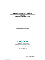
【Panel layout】
Vertical view and bottom view Rear view
Front view
IT-ES3012G-IU-4GS IT-ES3012G-IU-8GT
1. Ground screw
2. Terminal block for relay output
3. Console port
4. Terminal block for power input
5. DIP switches
6. DIN-Rail mounting kit
7. Relay alarm indicator
8. Power indicator
9. System running indicator
10. Gigabit RJ45 port
11. Gigabit Ethernet port Link/ACT indicator
12. Gigabit SFP port

【Power supply input】
The switch top panel provides a 4-pin power supply input
terminal block, support DC input. DC power supply input
supported redundancy function, provided PWR1 and PWR2
power input, can use for single, and can connect 2
separately power supply system, use 1 pair terminal block
connect the device at the same time. If one of the power
systems broke, the device can work un-interruptible. Built-in
overcorrect protection, Reverse connection protection.
Voltage input range is 12~48VDC (terminal block defined
as: V1-、V1+、V2-、V2+).
【Dimension】
Unit (mm)
【DIP Switch】
The top panel provides a 4-pin DIP switch to do function
configure (ON to enable effectively). 1 is power alarm
function. 2, 3 and 4 are reserved. Please power off and
power on when you change the status of a DIP switch.
【Relay connection】
Relay access terminals in the top panel of the device.
Between the two terminal relay, as an open circuit state in
normal no alarm state, when there is any alarm information
to the closed state. The two terminal block connector is used
to detect the power failure. The two wires attached to the
Fault contacts form an open circuit when the device has lost
power supply from one of the DC power input is a failure.
【Communication connector】
10/100/1000Base-T(X) Ethernet port
The pinout of RJ45 port display as below, connect by UTP or
STP. The connect distance is no more than 100m.
1000Mbps is used 120Ω of UTP 5e; 100Mbps is used 120Ω
of UTP 5; 10Mbps is used 120Ω of UTP 3, 4, 5.
RJ45 port support automatic MDI/MDI-X operation. That can
connect the PC, Server, Converter and HUB. Pin 1, 2, 3, 4, 5,
6, 7, 8 Corresponding connections in MDI. 1→3, 2→6, 3→1,
4→7, 5→8, 6→2, 7→4, 8→5, are used as cross wiring in the
MDI-X port of Converter and HUB. In MDI/MDI-X,
100/1000Base-TX PIN defines is as follows:
PIN
MDI
MDI-X
1
BI_DA+/TX+
BI_DB+/RX+
2
BI_DA-/TX-
BI_DB-/RX-
3
BI_DB+/RX+
BI_DA+/TX+
4
BI_DC+/—
BI_DD+/—
5
BI_DC-/—
BI_DD-/—
6
BI_DB-/RX-
BI_DA-/TX-
7
BI_DD+/—
BI_DC+/—
8
BI_DD-/—
BI_DC-/—
Note: 10Base-T/100Base-TX, “TX±” transmit data±, “RX±” receive data±,
“—”not use.
10/100Base-T(X) MDI (straight-through cable)
10/100Base-T(X) MDI-X (Cross over cable)
Gigabit MDI (straight-through cable)
Gigabit MDI-X (Cross over cable)
MDI/MDI-X auto connection makes switch easily to use for
customers without considering the type of network cable.
1 8

1000Base SFP fiber port (mini-GBIC)
1000Base-SFP fiber port adopts Gigabit mini-GBIC
transmission, can choose different SFP module according to
different transfer distance. Fiber interface must use for the
pair, TX port is transmitted side, must connect to RX
(receive side). The fiber interface support loss line indicator.
Suppose: If you make your own cable, we suggest labeling
the two sides of the same line with the same letter (A-to-A
and B-to-B, shown as below, or A1-to-A2 and B1-to-B2).
【LED Indicator】
LED indicator light on the front panel of product, the function
of each LED is described in the table as below.
System indication LED
LED
State
Description
RUN
ON
System is running well
OFF
System is not running well
P1
ON
Power is being supplied to power
input PWR1
OFF
Power is not being supplied to
power input PWR1
P2
ON
Power is being supplied to power
input PWR2
OFF
Power is not being supplied to
power input PWR2
ALARM
ON
When the alarm is enabled, power
or the port’s link is inactive.
OFF
Power and the port’s link is active,
the alarm is disabled.
Link/ACT
(G1~G8/
G12)
ON
Port connection is active
OFF
Port connection is not active
Blinking
Data transmitted
【Installation】
Before installation, confirm that the work environment meets
the installation requirements, including the power needs and
abundant space. Whether it is close to the connection
equipment and other equipment are prepared or not.
1. Avoid in the sunshine, keep away from the heat
fountainhead or the area where in intense EMI.
2. Examine the cables and plugs that installation
requirement.
3. Examine whether the cables be seemly or not (less
than 100m) according to the reasonable scheme.
4. Power: 12 ~ 48VDC
5. Environment: Working temperature: -40~75℃
Storage temperature: -40~85℃
Relative humidity: 5%~95%
DIN Rail Installation
In order to use in industrial environments expediently, the
product adopts 35mm DIN-Rail installation, the installation
steps as below:
1. Examine the DIN-Rail attachment
2. Examine DIN Rail whether be firm and the position is
suitability or not.
3. Insert the top of the DIN-Rail into the slot just below the
stiff metal spring.
4. The DIN-Rail attachment unit will snap into place as
shown below.
Wiring Requirements
Cable laying needs to meet the following requirements:
1. It is needed to check whether the type, quantity and
specification of cable match the requirement before
cable laying;
2. It is needed to check the cable is damaged or not, factory
records and quality assurance booklet before cable
laying;
3. The required cable specification, quantity, direction and
laying position need to match construction requirements,
and cable length depends on actual position;
4. All the cable cannot have break-down and terminal in the
middle;
5. Cables should be straight in the hallways and turn;
6. Cable should be straight in the groove, and cannot
beyond the groove in case of holding back the inlet and
outlet holes. Cables should be banned and fixed when
they are out of the groove;
7. Pigtail cannot be tied and served as less as possible.
Swerving radius cannot be too small (small swerving
caused terrible loss of link). It's banding should be
moderate, not too tight, and should be separated from
other cables;
8. It should have corresponding simple signal at both sides
of the cable for maintaining.

【Specification】
Technology
Standard: IEEE802.3, IEEE802.3u, IEEE802.3z/ab
Exchange attribute
100M forward speed: 148810pps
1000M forward speed: 1488100pps
Transmit mode: store and forward
System exchange bandwidth: 24G
MAC address table: 8K
Memory: 4Mbit
Interface
Gigabit RJ45 port: 10/100 /1000Base-T(X) auto speed
control, Half/full duplex and MDI/MDI-X auto detect
Gigabit SFP port: 1000Base-X, SFP slots
Console port: Reserved
Alarm port: 2-pin 7.62mm spacing terminal block
1 channel relay alarm output
Transfer distance
Twisted cable: 100M (standard CAT5/CAT5e cable)
Multi-mode: 1310nm, 2Km
Single-mode: 1310nm, 20/40Km
1550nm, 60/80/100/120Km
LED indicator
Run indicator: RUN
Interface indicator: Link (G1~G8/G12)
Power supply indicator: P1, P2
Alarm indicator: ALARM
Power supply
Input Voltage: 12~48VDC
Type of input: 4-pin 7.62 mm spacing terminal block
DC support reverse connection
DC support redundant power supply
Consumption
IT-ES3012G-IU-4GS
No-load consumption: 4.85W@24VDC
Full-load consumption: 10.32W@24VDC
IT-ES3012G-IU-8GT
No-load consumption: 4.35W@24VDC
Full-load consumption: 9.56W@24VDC
Working environment
Working temperature: -40~75℃
Storage temperature: -40~85℃
Relative Humidity: 5%~95 %( no condensation)
Mechanical Structure
Shell: IP40 protect grade, metal shell
Installation: DIN-Rail mounts
Weight: 960g
Size (W×H×D): 70mm×160mm×130mm
Industry Standard
EMI: FCC Part 15, CISPR (EN55022) class A
EMS: IEC 61000-4-2 (ESD), Level 4
IEC 61000-4-4 (EFT), Level 4
IEC 61000-4-5 (Surge), Level 4
Shock: IEC 60068-2-27
Free fall: IEC 60068-2-32
Vibration: IEC 60068-2-6
Certification
CE, FCC, RoHS, UL508 (Pending)
Warranty: 5 years
Intellisystem Technology
/