
SHOT BLASTING KIT 22.6KG/40KG CAPACITY
MODEL NO’S: SB994, SB995
Thank you for purchasing a Sealey product. Manufactured to a high standard, this product will, if used according to these instructions,
and properly maintained, give you years of trouble free performance.
IMPORTANT: PLEASE READ THESE INSTRUCTIONS CAREFULLY. NOTE THE SAFE OPERATIONAL REQUIREMENTS, WARNINGS & CAUTIONS. USE
THE PRODUCT CORRECTLY AND WITH CARE FOR THE PURPOSE FOR WHICH IT IS INTENDED. FAILURE TO DO SO MAY CAUSE DAMAGE AND/OR
PERSONAL INJURY AND WILL INVALIDATE THE WARRANTY. KEEP THESE INSTRUCTIONS SAFE FOR FUTURE USE.
1. SAFETY
WARNING! Turn off, or disconnect from, air supply before servicing or performing any maintenance and when unit is not in use.
Failure to comply with this instruction may damage the unit and will invalidate your warranty.
WARNING! Wear approved ear, eye, hand and respiratory protection when operating the blaster. A full range of personal safety
equipment is available from your Sealey stockists.
9 Maintain correct balance and ensure firm footing.
9 Spillages of abrasive material, which may be slippery, must be cleaned up immediately to avoid injury.
9 Locate blaster in a suitable, well ventilated, work area. Keep area clean and tidy and free from unrelated materials, and ensure that there
is adequate lighting.
9 Maintain the blaster in good condition (use an authorised service agent).
9 Replace or repair damaged parts. Use recommended parts only. Non-authorised parts may be dangerous and will invalidate the warranty.
9 Keep the unit clean for best and safest performance.
9 Remove ill fitting clothing. Remove ties, watches, rings, other loose jewellery and contain long hair.
9 Always keep the blast nozzle directed at the work piece.
9 If a failure or malfunction occurs immediately disconnect from air supply.
9 Keep all other persons away from the working area. Contact with high pressure blast or inhaling the dust generated is dangerous.
8 DO NOT use the blaster for any purpose other than that for which it is designed.
8 DO NOT operate the blaster if any parts are missing or damaged as this may cause failure and/or personal injury.
8 DO NOT use any abrasive which contains free silica. We recommend Sealey Shot Blasting Grit.
8 DO NOT attempt to clear a blocked nozzle while the unit is pressurised.
8 DO NOT allow untrained persons to operate the blaster.
8 DO NOT get the blaster wet or use in damp or wet locations or areas where there is condensation.
8 DO NOT leave the blaster operating unattended.
8 DO NOT operate the blaster when you are tired, under the influence of alcohol, drugs or intoxicating medication.
8 DO NOT stand or sit on the blaster.
8 DO NOT direct air from the air hose at yourself or others.
8 DO NOT operate system with air supply exceeding 125psi (8.6bar).
2. INTRODUCTION
Compact and portable shot blasting kit. Large capacity hopper with handle and heavy-duty rubber wheels for easy manoeuvrability. Supplied with
3m grit hose, tted with a heavy-duty shot blasting gun and four ceramic nozzles.
3. SPECIFICATION
4. AIR SUPPLY
WARNING! Ensure the air supply does not exceed 125psi (8.6 bar) while operating the unit. Too high an air pressure will shorten the
life of the unit due to excessive wear and may cause damage and/or personal injury.
9 Ensure the blaster air valve (trigger) is in the ‘Off’ position before connecting to the air supply.
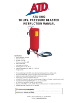
9 Keep the air hose between the compressor and the unit a reasonable length and install an air filter and water separator (fig.1).
9 Drain the air tank daily. Water in the air line will damage the unit.
9 The recommended hook-up procedure is shown in fig.1.
9 The minimum hose diameter should be 1/4” I.D. and fittings must have the same inside dimensions.
SB994,SB995 Issue:5 (3) 12/11/21
Original Language Version
© Jack Sealey Limited
Refer to
instruction
manual
Wear a mask Wear
protective
gloves
Wear ear
protection
Wear eye
protection
SB994 SB995
Air Consumption: 10-16cfm
Inlet size: 1/4” BSP
Maximum Fill Weight: 22.6kg 40kg
Nozzle Size(s): 4, 5, 6, 7mm
Operating Pressure: 60-125psi
Overall Dimensions (W x D x H): 330 x 370 x 685mm 432 x 458 x 940mm

9 Use correct hoses and fittings. DO NOT use quick change couplings as they add weight and can cause failure due to vibration. Add a
leader hose and connect coupling between this and supply hose.
9 Keep hoses away from heat, oil and sharp edges. Check hoses for wear and ensure that all connections are secure.
5. ASSEMBLY
WARNING! Before operating the unit ensure you read, understand and apply Section 1 Safety Instructions.
NOTE: Numbers in brackets refer to the item numbers in the Parts List.
5.1. MODEL SB994 (Refer to SB994 parts diagram)
5.1.1. Attach lower handle axle assembly (4) to the barrel assembly (1) using screws (8), washers (6) and nuts (5), do not fully tighten.
5.1.2. Slide the upper handle (2) onto the lower handle and align the hole, using screw (7), washers (6) push the screw through into the
barrel assembly and secure using washer (6) and nut (5). Tighten all screws securely.
5.1.3. Push a split pin (11) through the inner hole of the axle and secure using pliers to bend round the pin, slide a washer (‘*O-ring’) (9) on the
axle so that it butts up against the split pin, slide a wheel (10) onto the axle, followed by another washer (*) (9) and secure with a split pin
through the outer hole in the axle shaft. Repeat for the other side.
5.1.4. Slide the front leg (3) into the tube on the barrel assembly, align the holes and secure using screw (7), washers (6) and nut (5).
5.1.5. Slide a hose clamp (13) over the end of the hose and push onto the outlet tube of the barrel assembly.
NOTE: DO NOT push the hose on so far that it covers the vent hole in the outlet tube.
5.1.6. Connect the other end of the hose to the sanding gun (12) using hose clamp (13).
5.1.7. Fit an appropriate air line connection compatible with your air supply, see section 4 and the Specification in section 2.
5.2. MODEL SB995 (Refer to SB995 parts diagram)
5.2.1. Loosely attach handle (3) to barrel assembly (1) using screws (7), washers (5) and nuts (6).
5.2.2. Loosely attach base support (2) to the barrel assembly using screws (4) washers (5) and nuts (6), ensure that the gun holder is facing
upwards as shown in the parts diagram.
5.2.3. Attach the base bar (8) to the base support bar, align the holes at the rear of the base with the holes in the handle (3) and slide the
axle (9) through both the handle and the base section to locate. Ensure that the axle sticks out evenly on both sides of the handle.
5.2.4. Slide washer (10) and wheel (11) onto one side of the axle, slide the other washer onto the axle and secure using split pin (12).
Repeat for the other wheel assembly.
5.2.5. Tighten all screws, ensuring that the handle and base are square with the barrel assembly.
5.2.6. Attach the end of the hose with the right angle bend (15) to the outlet tube of the barrel assembly using hose clamp (14), ensuring that
the vent hole in the tube is facing upwards.
5.2.7. Attach the other end of the hose onto the guns using hose clamp (14).
5.2.8. Fit an appropriate air line connection compatible with your air supply, see section 4 and the Specification in section 2.
6. OPERATION
WARNING! Ensure that you read, understand and apply the safety instructions in Section 1 before use.
WARNING! Wear approved ear, eye, hand and respiratory protection when operating the blaster.
WARNING! Ensure the air supply does not exceed 120psi (8.2bar) while operating the unit.
6.1. Fill the hopper with the required abrasive, checking to ensure it is clean and dry.
6.2. Attach an airline to the gun and press the trigger.
6.3. Before blasting unfamiliar material, spot test to ensure that damage/pitting will not occur to the material.
6.4. Use even passes of the blaster to remove material such as rust, body filler or other soft materials. DO NOT blast in any one area
for more than a few seconds at a time.
6.5. The unit is supplied with 4 ceramic nozzles ranging from 4 to 7mm, select the appropriate nozzle for the task (fig.2).
6.6. To change the nozzle, disconnect from the air supply and unscrew the head screw, insert the nozzle as shown in fig.2 and refit the head
screw.
WARNING! DO NOT use the sand blaster without a nozzle fitted.
fig.1fig.2
Original Language Version
© Jack Sealey Limited
Sealey Group, Kempson Way, Suffolk Business Park, Bury St Edmunds, Suffolk. IP32 7AR
01284 757500 01284 703534 sales@sealey.co.uk www.sealey.co.uk
ENVIRONMENT PROTECTION
Recycle unwanted materials instead of disposing of them as waste. All tools, accessories and packaging should be sorted, taken to
a recycling centre and disposed of in a manner which is compatible with the environment. When the product becomes completely
unserviceable and requires disposal, drain any fluids (if applicable) into approved containers and dispose of the product and fluids
according to local regulations.
Note: It is our policy to continually improve products and as such we reserve the right to alter data, specifications and component parts without prior
notice.
Important: No Liability is accepted for incorrect use of this product.
Warranty: Guarantee is 12 months from purchase date, proof of which is required for any claim.
SB994,SB995 Issue:5 (3) 12/11/21
-
 1
1
-
 2
2


Ask a question and I''ll find the answer in the document
Finding information in a document is now easier with AI
Related papers
-
Sealey SSG1P3.V3 Operating instructions
-
Sealey SCS906 Operating instructions
-
-
Sealey SB99.KIT Operating instructions
-
-
-
Sealey PW2400 Operating instructions
-
Sealey AK41.V3 Operating instructions
-
-
Other documents
-
 Borum Industrial BSB3033 User manual
-
TradeQuip Professional 3032T Owner's manual
-
RED LABEL RLSB90L 90 Litre Mobile Sandblasting Unit Owner's manual
-
 ATD Tools 8402 User manual
-
 Allsource Import Pressure Blaster 20 Gal 41003 User manual
-
TradeQuip Professional 3060 Owner's manual
-
 ATD Tools ATD-8402 User manual
-
ALC 40018 User manual
-
Harbor Freight Tools 100 lb. Dual Tank Abrasive Blaster User manual
-
Allsource 4120010 User manual


