Page is loading ...

OPERATING
INSTRUCTIONS
MAR-B3089
AM/FM Stereo Radio with
Full Detachable Panel and
Auto-Reverse Cassette Player
ISO Mounting with
Removable Trim Ring

CONTENTS
Accessories ....................................................................................................1
DIN Front-Mount (Method A) ..........................................................................2
Installation.......................................................................................................3
Electrical Connections...............................................................................4 - 5
Using the Detachable Front Panel.............................................................6 - 7
Operation.................................................................................................8 - 11
Specifications ...............................................................................................12
Warranty........................................................................................................13
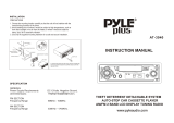
ACCESSORIES
Please retain the carton and packing materials, as this is the best protection for the
unit should it be necessary to return it for servicing.
Check the packing carefully for the following accessories:
(1) 2 x Screw 5x14mm (used to fix the mounting bracket to the eye/support bracket)
(2) 1 x Hexagon Nut (used for fixing the mounting bracket to the eye/support bracket)
(3) 1 x Metal Bracket
(4) 2 x Release Key
(5) 4 x Screw 4x6mm
(used to fix the factory radio mounting bracket to the eye/support bracket)
(6) 4 x Washer Head Screw 5x6mm
(used to fix the factory radio mounting bracket to the eye/support bracket)
(7) 1 x Screw 2x4mm (used to secure the front panel for anti-theft purposes)
(1) (2) (3)
Screw Hexagon Nut Metal Bracket
(4) (5) (6) (7)
Release Key Screw Washer Head Screw Screw
CAUTION
• This unit is designed to operate on 12 volts DC, negative ground electrical systems
only.
• When fuse replacement is necessary, use only an 10 amp fuse. Do not replace with
a higher rated fuse. If the fuse blows often, carefully check all electrical connections
for any short circuits and have your car’s voltage regulator checked also.
• Do not install the unit where it will be exposed to direct sunlight or hot air discharged
from the car heater.
• Do not expose the unit to water or moisture.
• This AM/FM Radio with Cassette should not be adjusted or repaired by anyone
except qualified service personnel. If servicing is required, return the unit to an
authorized SANYO mobile audio dealer.
• Changes or modifications not expressly approved by SANYO may void the user’s
authority to operate this equipment.
• This device complies with Part 15 of the FCC Rules. Operation is subject to the
following two conditions:
(1) This device may not cause harmful interference, and
(2) this device must accept any interference received, including interference that
may cause undesired operation.
1

2
DIN FRONT-MOUNT (METHOD A)
Installation with the rubber bushing
1. Dashboard
2. Half Sleeve
After inserting the sleeve into the
dashboard, select the appropriate tabs
according to the thickness of the
dashboard material, then bend them
outward to secure the sleeve in place.
3. Screw
Installation without the rubber bushing
1. Dashboard
2. Nut (5mm)
3. Screw (5 x 14mm)
4. Strap
Be sure to use the strap to secure the
back of the unit. The strap can be bent
by hand to the desired angle.
Removing the unit
1. Removable Trim Ring
2. Grasp the center area of the trim ring
from the top or bottom edge, then pull
outward to remove it. (When reattaching
the trim ring, carefully align it with the
front panel of the unit, then press it
into place.
3. Levers
Insert the levers supplied with the unit
into the grooves on both sides of the
chassis (as shown in the figure) until they
click into place. Carefully pull outward
to remove the unit.
1
3
2
182
53
1
2
4
3
1
2
3

INSTALLATION
Note:
• Before installing the unit, connect the wiring temporarily and verify that the unit is
operating properly.
• Use only the parts included with the unit to ensure proper installation. The use of
unauthorized parts can cause malfunctions.
• Consult your dealer if the installation requires drilling of holes, or other modifications
to the vehicle.
• Install the unit where it will not interfere with the driver’s ability to control the vehicle
or cause injury to a passenger in the event of a sudden stop.
• To ensure optimum performance, do not install the unit at an angle of more than
30° from the horizontal.
DIN FRONT/REAR-MOUNT
This unit can be installed either from the front (by using the mounting sleeve), or from
the rear (by using the threaded mounting holes on the sides of the unit). For details,
refer to the illustrations of the following installation methods.
Installing the unit by using the factory radio
mounting bracket(s).
1. Determine the correct position where
the holes on the mounting bracket and
the side of the unit match.
Mount 2 screws on each side of the unit.
Use the washer head screws (5x7mm)
and the holes marked “N” or “T” or the
pan head screws (4x8mm) and the holes
marked “S”.
(The holes marked “T” are for Toyota
and the holes marked “N” are for
Nissan.)
2. Factory radio mounting bracket
3. Dashboard or Console
Note: The support strap, outer trim ring
and half-sleeve are not used in the method
B installation.
3
30˚
2
3
1
T N
N
T
N
T
S
S
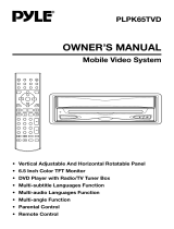
ELECTRICAL CONNECTIONS
WIRING FOR MAR-B3089
Caution
• DO NOT connect any speaker wires to the metal body or chassis of the vehicle.
• Connect each speaker wire directly to each speaker terminal.
• All speaker common (–) wires must remain floating.
1 Antenna socket
• Insert the plug from the antenna installed in your vehicle into this socket.
(If your vehicle has a dual antenna system, a dual antenna to single antenna
cable adaptor may be required.)
2 +12V Constant Power Supply (Yellow)
• Connect this wire to the +12V power terminal which receives power continuously.
3 +12V Accessory/Switched (Red)
• Connect this wire to the terminal which receives power while the ignition switch
is ON or in the ACCESSORY position.
• If the ignition switch does not have an ACC position, connect this wire to a
+12V power terminal which receives power continuously. (Same as item 2.)
4 Ground wire (Black)
• Connect this wire to the vehicle chassis.
5 Power Antenna/Amplifier Turn On (Blue/Red)
• Connect this wire to the control terminal of a Power Antenna or an external
amplifier.
• When not using a Power Antenna or an external amplifier, this wire is not
connected.
4
(White)
(White/Black)
(Gray)
(Gray/Black)
(Green)
(Green/Black)
(Violet)
(Violet/Black)
Front Left
Speaker
Front Right
Speaker
Rear Left
Speaker
Rear Right
Speaker
+12V Constant Power Supply (yellow)
+12V Accessory/Switched (Red)
Ground Wire (Black)
Power Antenna/Amplifier Turn On (Blue/Red)

5
- When fuse replacement is necessary, remove the blown fuse by opening the Filter
Box, then install a new 10 amp fuse (switched power supply) or 0.5 amp fuse
(constant power supply).
- RCA Line Out Jacks
Connect a patch cable (not supplied) from the White (left channel) and Red (right
channel) RCA line output jacks to the line input terminals of an external amplifier.

USING THE DETACHABLE FRONT PANEL
To Detach the Front Panel
1. Press the release button (REL). The right side of the panel will release from the
main unit.
2. Remove the front panel by pulling the left-hand side outward.
3. For safekeeping, store the front panel in the supplied protective case immediately
after removing it.
6
Releasing Button
Front Panel
Front Panel
Protective Case

7
To Reinstall the Front Panel
1. First, align the left side of the panel with the front of the unit, then press the right
side against the unit until it clicks into place. Do not force the panel into place.
2. Note:
If the front panel is not locked into the proper position, pushing the eject button
may not release the panel and the other control buttons may not function.
SECURITY
To avoid theft or loss of the front panel, you can inactivate the release knob by
installing the screw provided as shown.
Precautions when Handling the Front Panel
1. Do not drop the front panel.
2. Do not put pressure on the display or control buttons when detaching or reinstalling
the front panel.
3. Do not touch the contacts on the front panel or on the main unit body. It may result
in poor electrical contact.
4. If any dirt or foreign substances have adhered to the contacts, they can be removed
with a clean, dry cloth.
5. Do not expose the front panel to high temperatures or direct sunlight.
6. Do not expose the front panel to benzene, thinner, insecticides or any other strong
chemicals. These will damage the finish of the panel.
7. Do not attempt to disassemble the front panel.
8
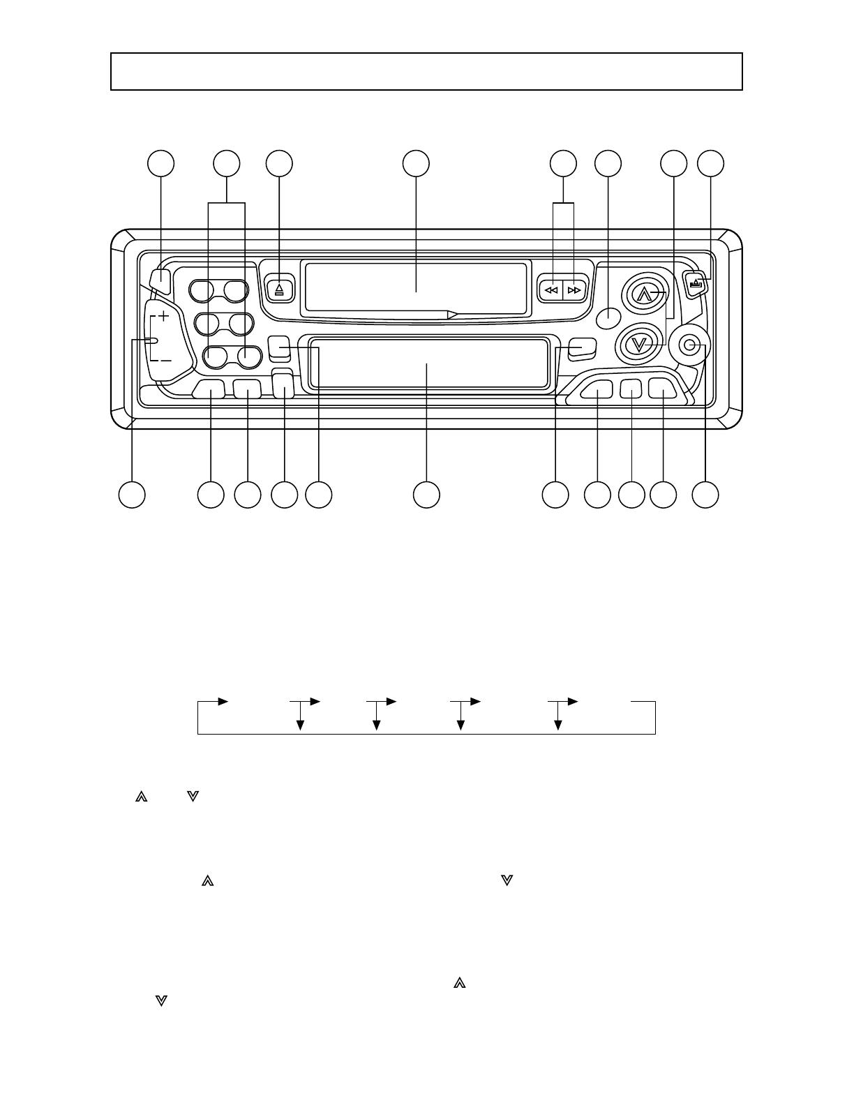
OPERATION
CONTROLS AND FUNCTION KEYS
1. PWR (=POWER)
Press the button to turn on the unit, press again to turn it off.
2. REL (=RELEASE)
Press the button to detach the faceplate.
3. SEL (=SELECT)
Press to select audio control mode. The desired mode can be selected as below:
Each mode is indicated on display. The initial state is Volume mode.
4. VOL (=VOLUME UP/DOWN)
Used for audio UP/DOWN control when the SEL button is pressed. Sound quality
is controlled as below:
• In volume mode:
Press ‘ ’ to increase volume level, and press ‘ ’ to decrease the level.
The volume level is updated correspondingly and its status is shown on the
display.
Note: The unit is initially set to volume mode.
• In bass mode:
While “BAS” is shown on display, press ‘ ’ to increase bass level, and press
‘ ’ to decrease the level.
The bass level is updated correspondingly and its status is shown on display.
1 14
1918 58 9712
16 17 15 2
10611 13
3 4
Volume Bass Treble Balance Fader
• In treble mode:
While “TRE” is shown on display, press ‘ ’ to increase treble level, and press
‘ ’ to decrease the level.
The treble level is updated correspondingly and its status is shown on display.
• In balance mode:
While “BAL” is shown on display, press ‘ ’ to shift sound level to right speaker,
press ‘ ’ to shift sound level to left speaker.
The shift point is updated correspondingly and its status is shown on the
display.
• In fader mode:
This function controls the balance between front and rear speakers of 4 speakers
system.
While “FAD” is shown on display, press ‘ ’ to shift sound level to front
speakers, press ‘ ’ to shift sound level to rear speakers.
The shift point is updated correspondingly and its status is shown on the
display.
5. MUT (=MUTE)
Press the button to cut the sound output and LCD display will indicate “MUTE”
and flash. Press any button to release the mode and recover the previous volume
level.
6. LOU (=LOUDNESS)
Press the button to reinforce the bass especially when listening at low volume
level, and LCD display will indicate “LOUD”. Press it again to release the mode.
7. DSP (=DISPLAY)
During radio operation, press the button to recall the time display. Pressing it
again or activating any tuning function, will cause the display return to station
frequency read-out.
Time Setting
Press and hold DSP button, then press the tune buttons ‘ + ’ side to adjust the
minute, ‘ – ’ side to adjust the hour.
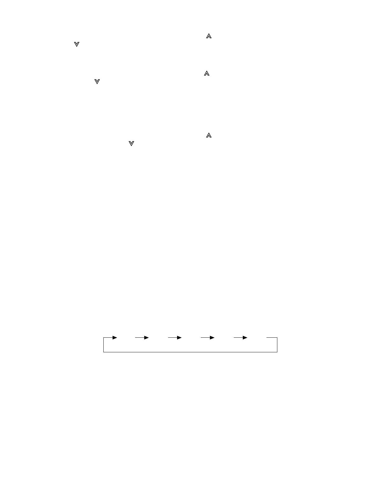
8. BND (=BAND)
Press the button to switch the reception broadcast band in following order:
9. LOC (=LOCAL/DISTANT)
Press the button to switch to reception of local station with strong signals or
distant stations with weak signals. The unit is initially set to distance mode.
Press the button to switch into local mode and LCD display will indicate “LOC”.
Press it again to release the mode.
Note: This function is in effect during AUTO SEEK or AMS operation.
10. SCN (=SCANNING)
Press SCN button to set the function to scan mode, which scans for higher
frequency stations with receivable signals and stays on each station for several
seconds. During the period of scanning, press it again to stop scanning and
release the mode.
9
FM1 FM2 FM3 AM1 AM2

10
11. MOD (=MODE)
Press the button to select radio, tape or CD mode.
When a tape is inserted, each time the button is pressed, the next input source
is selected in the following order:
12. + TUNE – (=TUNE UP/DOWN)
• Manual Tune Up/Down
Repeatedly press tune buttons ‘ – ’ side or ‘ + ’ side for tuning frequency
downward or upward in order to substitute the seek function in the weakest
reception stations.
• Seek Tune Up/Down
Press and hold tune buttons ‘ – ’ side or ‘ + ’ side for several seconds for auto
tuning frequency downward or upward to next station with a strong signal.
13. AMS (=AUTO MEMORY STORING)
• Preset Scan
Press AMS button shortly to scan the stored stations.
During the preset scanning, it will stop at each station for several seconds and
the number of the channel will flash on the display. To stop the scanning
operation, press either AMS button or any one of the channel buttons.
• Auto Memory Store
Press AMS button for several seconds to enable auto seek function in the
selected band and store the first six stations which are found. LCD display
indicates “ATP” during auto memory store operation.
14. M1, M2, M3, M4, M5, M6
Press to preset stations at tuner mode. With this system, a total of 30 stations
can be stored in the memory’s six buttons. The stations might be FM1, FM2,
FM3, AM1 and AM2 bands.
The operation is as follows:
• Store in Memory
Press and hold desired memory location button for several seconds.
The current listening station will be stored into the number button.
• Retrieve a Preset Station
Press any one of the buttons (1 to 6) to retrieve a station which had been stored
in the memory in advance. The chosen number is shown on display.
15. PROGRAM BUTTON
These 2 buttons perform the dual functions of changing the direction of tape
playback and fast forward/rewind of the tape.
• Change Tape Playback Direction
Press both buttons together to play the other side of a tape.
• Fast Forward/Rewind
Press the button with the double arrows pointing the same direction as the
direction indicator on the LCD to fast forward, press other button in the opposite
direction to fast rewind.
RADIO CD TAPE

11
16. EJECT
Push down to eject the cassette tape.
17. CASSETTE COMPARTMENT
Insert a cassette tape into the cassette compartment. The cassette mechanism
will load it in play mode.
18. FREQUENCY DISPLAY
Exhibits the current frequency and activated function state.
19. CD IN JACK
The unit can be connected to a portable CD player through this jack.

12
MODEL MAR-B3089 SPECIFICATIONS
FM TUNER SECTION
Frequency Range ......................................................................87.5 MHz ~ 107.9 MHz
Usable Sensitivity ...........................................................................................17.23 dBf
50 dB Quieting Sensitivity...............................................................................20.76 dBf
Frequency Response ............................................................................20 Hz ~ 15 KHz
I.F. Response Ratio ...............................................................................................80 dB
Image Response Ratio..........................................................................................50 dB
Signal-to Noise Ratio............................................................................................60 dB
Alternate Channel Selectivity ................................................................................50 dB
Stereo Separation .................................................................................................30 dB
Capture Ratio.......................................................................................................1.5 dB
Antenna Impedance.................................................................................................75Ω
AM TUNER SECTION
Frequency Range..........................................................................530 KHz ~ 1710 KHz
Usable Sensitivity (S/N 20 dB) ..............................................................................20 µV
I.F. Response Ratio ...............................................................................................60 dB
Image Response Ratio..........................................................................................36 dB
Signal-to-Noise Ratio ...........................................................................................50 dB
Antenna Impedance.................................................................................................75Ω
CASSETTE DECK SECTION
Wow & Flutter (WRMS) ..........................................................................................0.1%
Fast Winding (C-60) ..........................................................................................150 sec.
Frequency Response ............................................................................50 Hz ~ 14 KHz
Channel Separation (1 KHz)..................................................................................35 dB
Signal-to-Noise Ratio ...........................................................................................52 dB
AUDIO SECTION
Maximum Power Output ...................................................................................35W x 4
Load Impedance........................................................................................................4Ω
GENERAL
Operating Voltage ............................................................................12V (14.4V Typical)
Operating Current Maximum ...................................................................................10A
Installation Size (W x H x D).............................................................180 x 50 x 165 mm
IMPORTANT INFORMATION
Because its products are subject to continuous improvement, SANYO reserves
the right to modify product designs and specifications without notice and without
incurring any obligation.

13
SANYO MOBILE AUDIO
MODEL MAR-B3089 LIMITED WARRANTY
OBLIGATIONS
In order to obtain warranty service, the product must be delivered to and picked up from an Authorized
Sanyo Factory Service Center at the user’s expense, unless specifically stated otherwise in this
warranty. The names and addresses of Authorized Sanyo Service Centers may be obtained by calling
the toll-free number listed below.
For product operation, authorized service center referral, service assistance or problem resolution, call
CUSTOMER INFORMATION 1-800-421-6382
Weekdays 8:00 AM - 5:00 PM Pacific Time
THIS WARRANTY IS VALID ONLY ON SANYO PRODUCTS PURCHASED AND USED IN THE
UNITED STATES OF AMERICA.
THIS WARRANTY APPLIES ONLY TO THE ORIGINAL RETAIL USER, AND DOES NOT APPLY TO
PRODUCTS USED FOR ANY INDUSTRIAL, PROFESSIONAL OR COMMERCIAL PURPOSE. THE
ORIGINAL DATED BILL OF SALE OR SALES SLIP MUST BE SUBMITTED TO THE AUTHORIZED
SANYO SERVICE CENTER AT THE TIME WARRANTY SERVICE IS REQUESTED.
Subject to the OBLIGATIONS above and EXCLUSIONS below, SANYO FISHER COMPANY (SFC)
warrants this SANYO product against defects in materials and workmanship for the periods specified
below. SFC will repair or replace (at its option) the product and any of its parts which fail to conform
to this warranty with new or reconditioned products or parts. The warranty period commences on the
date the product was first purchased at retail.
LABOR PARTS
1 YEAR 1 YEAR
EXCLUSIONS
This warranty does not cover (A) the adjustment of customer-operated controls as explained in the
appropriate model’s instruction manual, or (B) the repair of any product whose serial number has been
altered, defaced or removed.
This warranty does not apply to the cabinet or cosmetic parts, knobs or routine maintenance.
This warranty does not apply to the elimination of car static or motor noise, correction of antenna
problems, or damage to compact discs, speakers, accessories or vehicle electrical systems.
This warranty does not apply to repairs or replacements necessitated by any cause beyond the control
of SFC including, but not limited to, any malfunction, defect or failure caused by or resulting from
unauthorized service or parts, improper maintenance, operation contrary to furnished instructions,
shipping or transit accidents, modification or repair by the user, abuse, misuse, neglect, accident,
incorrect power line voltage, fire, flood or other Acts of God, or normal wear and tear.
The foregoing is in lieu of all other express warranties and SFC does not assume or authorize any party
to assume for it any other obligation or liability.
THE DURATION OF ANY WARRANTIES WHICH MAY BE IMPLIED BY LAW (INCLUDING THE
WARRANTIES OF MERCHANTABILITY AND FITNESS) IS LIMITED TO THE TERM OF THIS WARRANTY
IN NO EVENT SHALL SFC BE LIABLE FOR SPECIAL, INCIDENTAL OR CONSEQUENTIAL DAMAGES
ARISING FROM OWNERSHIP OR USE OF THIS PRODUCT, OR FOR ANY DELAY IN THE
PERFORMANCE OF ITS OBLIGATIONS UNDER THIS WARRANTY DUE TO CAUSES BEYOND ITS
CONTROL.
SOME STATES DO NOT ALLOW LIMITATIONS ON HOW LONG AN IMPLIED WARRANTY LASTS
AND/OR DO NOT ALLOW THE EXCLUSION OR LIMITATION OF CONSEQUENTIAL DAMAGES, SO
THE ABOVE LIMITATIONS AND EXCLUSIONS MAY NOT APPLY TO YOU.
THIS WARRANTY GIVES YOU SPECIFIC LEGAL RIGHTS. YOU MAY HAVE OTHER RIGHTS, WHICH
VARY FROM STATE TO STATE.
For your protection in the event of theft or loss of this product, please fill in the information below for
your own personal records.
Model No. Serial No.
(Located on back or bottom side of unit)
Date of Purchase Purchase Price
Where Purchased

21605 Plummer Street
Chatsworth, CA91311
MAR-B3089. Issue Number 1.
Printed in Hong Kong
88-P1020-15
/