Page is loading ...

Rev. 070605
More than just power.
TM
R1224DC68220 Series
Rack Mount CCTV Power Supplies
Installation Guide
Models Include:
R1224DC68220
- 12VDC or 24VDC @ 6A.
- Eight (8) Fuse Protected Outputs.
R1224DC68CB220
- 12VDC or 24VDC @ 6A.
- Eight (8) PTC Protected Outputs.

- 2 - R1224DC68220 Series
Overview:
Altronix R1224DC68220 Series Rack Mount Power Supplies provides 12VDC or 24VDC @ 6A via eight (8)
fuse or PTC protected outputs for powering CCTV cameras, heaters, and other video accessories.
Eight (8) Output Rack Mount Configuration Reference Chart:
Altronix
Model Number
Total Output
Current (Power)
Output Voltage
(VDC)
Number of
Outputs
PTC
Protected
Outputs
(auto-
resettable)
Fuse
Protected
Outputs
Individual
Output
Current (max
per output,
not to exceed
total output
current)
220VAC
50/60Hz
Input Current
R1224DC68220
6A
12
8 –
P
3.5A 0.9A
24
R1224DC68CB220
12
8
P
– 2.5A 0.9A
24
Specifications:
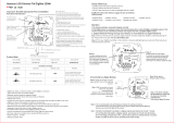
Installation Instructions:
1. Unit is factory set at 12VDC. To adjust the output voltage remove the bottom cover to access DIP switch
on the power supply board (Fig. 1a, pg. 3).
2. Mount unit in the desired rack location (Space unit at least 3” from any video monitors).
3. Set power switch on the back of the unit to the OFF position (Fig. 1e, pg. 3).
4. Plug power cord into a grounded 220VAC 50/60 Hz receptacle (Fig. 1d, pg. 3).
5. Set power switch to the ON (RESET) position and measure output voltage before connecting devices
(Fig. 1e, pg. 3). This helps avoiding potential damage.
6. Set power switch on the back of the unit to the OFF position (Fig. 1e, pg. 3).
7. Connect devices to the removable terminal blocks marked [1P & 1N] through [8P & 8N] (Fig. 1c, pg. 3).
When wiring is completed on terminal blocks, they can be locked down by tightening screw flanges.
All terminals with common suffix (P) “1P, 2P...” are the same polarity (positive).
All terminals with common suffix (N) “1N, 2N...” are the same polarity (negative).
8. Upon completion of the wiring, set power switch on back of unit to the ON (RESET) position (Fig. 1e, pg. 3).
9. Green power LEDs on faceplate will illuminate when AC power is present. When an output is in a trouble
condition (blown fuse or tripped PTC), the corresponding LED will not be illuminated (Fig. 1, pg. 3).
a. Blown fuse (R1224DC68220) - Set power switch on the back of the unit to the OFF position
(Fig. 1e, pg. 3). Remove front faceplate to access fuses. Replace with fuses rated @ 3.5A/250VA
(Altronix model # Fuse1).
b. Tripped PTC (R1224DC68CB220) - To reset PTC, set power switch on the back of unit to the OFF
position. After approximately 30 secs. set power switch to the ON (RESET) position (Fig. 1e, pg. 3).
10. Power switch with built-in circuit breaker:
OFF position - Switch not illuminated. Outputs not powered.
RESET (ON) position - Switch illuminated. Outputs powered.
Circuit breaker tripped - Switch not illuminated. Power LEDs on faceplate are not illuminated. Outputs not
powered. To reset circuit breaker set power switch to the ON (RESET) position (Fig. 1e, pg. 3).
Input:
• 220VAC, 50/60Hz, 0.9A.
Output:
• Eight (8) fuse or PTC protected outputs.
• 12VDC or 24VDC @ 6A
(0.75A per device, 3.5A max.)
• Outputs are rated @ 3.5A (fused) or 2.5A (PTC).
• Surge suppression.
Battery Backup:
• Built-in charger for sealed lead acid or
gel type batteries.
• Automatic switch over to stand-by battery when
AC fails.
• Maximum charge current 0.7A.
Features:
• Eight (8) power LEDs.
• Illuminated master power disconnect circuit breaker
with manual reset.
• 3-wire grounded line cord.
• Removable terminal blocks with
locking screw flange.
• Unit maintains camera synchronization.
• Spare fuses provided.
Mechanical:
• 2U rack mount chassis for use in standard
EIA 19” rack.
• Enclosure Dimensions (H x W x D approx.):
3.26” x 19.125” x 8.5” (83mm x 486mm x 216mm)

R1224DC68220 Series - 3 -
CAUTION: Equipment to be installed / serviced by authorized / trained personnel only.
Shut branch circuit power before installing / servicing equipment.
WARNING: To reduce the risk of fire or electric shock, do not expose the unit to rain or moisture.
This installation should be made by qualified service personnel and should conform to
the National Electrical Code and all local codes.
The lightning flash with arrowhead symbol within an equilateral triangle is intended to alert the user
to the presence of an insulated DANGEROUS VOLTAGE within the product’s enclosure that may
be of sufficient magnitude to constitute an electric shock.
The exclamation point within an equilateral triangle is intended to alert the user to the presence of
important operating and maintenance (servicing) instructions in the literature accompanying
the appliance.
CAUTION: To reduce the risk of electric shock do not open
enclosure. There are no user serviceable parts inside. Refer servicing
to qualified service personnel.
P
N
S
(Green Wire
Earth GND)
Power
LEDs
Power
LEDs
Strain Relief
Line Cord
Power Switch
Removable Terminal
Block
PTC1
Used
on PTC
Models
LG N
OFF ON
--- BAT + --- DC +
AC DC
5A 250V
SW1
OFF - 24V
ON - 12V
ON
Fig. 1
Fig. 1c Fig. 1d Fig. 1e
Fig. 1a Fig. 1b

- 4 - R1224DC68220 Series
Altronix is not responsible for any typographical errors.
140 58th Street, Brooklyn, New York 11220 USA | phone: 718-567-8181 | fax: 718-567-9056
website: www.altronix.com | e-mail: [email protected] | Lifetime Warranty | Made in U.S.A.
IIR1224DC68(CB)220 F19R
MEMBER
Rack Mechanical Drawing and Dimensions:
3.26” x 19.125” x 8.5” (83mm x 486mm x 216mm)
8.5"
216mm
3.26"
83mm
17.625"
447.7mm
0.75"
19.05mm
19.125"
486mm
View from back
View from front
BOTTOM
FACEPLATE
BACK
/