Page is loading ...

MANUAL 10040R4
INSTALLATION & OPERATION
MANUAL
Direct Steam Single and Twin Mixer Kettles
DLTM-40-(2) DLTM-60-(2) DLTM-80-(2) DLTM-100-(2)
WARNING
Improper installation, adjustment, alteration, service or maintenance can cause property damage, injury or death. Read
the installation, operating and maintenance instructions thoroughly before installing or servicing this equipment.
IMPORTANT FOR FUTURE REFERENCE
Please complete this information and retain this
manual for the life of the equipment:
Model #: ___________________________
Serial #: ___________________________
Date Purchased: ____________________
CROWN FOOD SERVICE EQUIPMENT
A Middleby Company
70 Oakdale Road, Downsview (Toronto) Ontario, Canada, M3N 1V9
Telephone: 919-762-1000 www.crownsteamgroup.com
Printed in Canada

INSTALLATION AND OPERATION MANUAL, DIRECT STEAM SINGLE & TWIN MIXER
KETTLE, MODELS DLTM-40 TO DLTM-100 AND DLTM-40-2 TO DLTM-100-2
1.0 IMPORTANT NOTES FOR INSTALLATION AND OPERATION
It is recommended that this manual be read thoroughly and that all instructions be followed
carefully.
This is the safety alert symbol. It is used to alert you to potential
personal injury hazards. Obey all safety messages that follow this
symbol to avoid possible injury or death.
WARNING: Improper installation, operation, adjustment, alteration,
service or maintenance can cause property damage, injury or death.
Read the installation, operating and maintenance instructions
thoroughly before installing, operating or servicing this equipment.
Intended for commercial use only. Not for household use.
This manual should be retained for future reference.
Part No. 10040R4 2 2018-12-05

INSTALLATION AND OPERATION MANUAL, DIRECT STEAM SINGLE & TWIN MIXER
KETTLE, MODELS DLTM-40 TO DLTM-100 AND DLTM-40-2 TO DLTM-100-2
TABLE OF CONTENTS
DESCRIPTION PAGE
1.0 Important Notes for Installation and Operation . . . . . . . . . . . . . . . . . . . . . . . . . . . . . . . . . . 2
2.0 Service Connections . . . . . . . . . . . . . . . . . . . . . . . . . . . . . . . . . . . . . . . . . . . . . . . . . . . . . 4
3.0 Introduction . . . . . . . . . . . . . . . . . . . . . . . . . . . . . . . . . . . . . . . . . . . . . . . . . . . . . . . . . . . . 6
4.0 Installation Instructions .. . . . . . . . . . . . . . . . . . . . . . . . . . . . . . . . . . . . . . . . . . . . . . . . . . . 7
5.0 Operating Instructions . . . . . . . . . . . . . . . . . . . . . . . . . . . . . . . . . . . . . . . . . . . . . . . . . . . . 8
6.0 Cleaning Instructions . . . . . . . . . . . . . . . . . . . . . . . . . . . . . . . . . . . . . . . . . . . . . . . . . . . 10
7.0 Maintenance . . . . . . . . . . . . . . . . . . . . . . . . . . . . . . . . . . . . . . . . . . . . . . . . . . . . . . . . . . 13
8.0 Troubleshooting . . . . . . . . . . . . . . . . . . . . . . . . . . . . . . . . . . . . . . . . . . . . . . . . . . . . . . . . 17
Appendix A, Material Safety Data Sheet . . . . . . . . . . . . . . . . . . . . . . . . . . . . . . . . . . . . . . . . . 21
Part No. 10040R4 3 2018-12-05

INSTALLATION AND OPERATION MANUAL, DIRECT STEAM SINGLE & TWIN MIXER
KETTLE, MODELS DLTM-40 TO DLTM-100 AND DLTM-40-2 TO DLTM-100-2
2.0 SERVICE CONNECTIONS
Part No. 10040R4 4 2018-12-05

INSTALLATION AND OPERATION MANUAL, DIRECT STEAM SINGLE & TWIN MIXER
KETTLE, MODELS DLTM-40 TO DLTM-100 AND DLTM-40-2 TO DLTM-100-2
2.0 SERVICE CONNECTIONS
Part No. 10040R4 5 2018-12-05

INSTALLATION AND OPERATION MANUAL, DIRECT STEAM SINGLE & TWIN MIXER
KETTLE, MODELS DLTM-40 TO DLTM-100 AND DLTM-40-2 TO DLTM-100-2
3.0 INTRODUCTION
DESCRIPTION
All Crown direct connected steam jacketed kettles pertaining to this manual are direct steam
operated pressure vessels of a double-wall stainless steel construction forming a steam
chamber (jacket) enveloping the lower two thirds of the kettle bowl surface. All kettles are
tilting, floor mounted in fixed positions on legs with adjustable flanged feet. All kettles are
equipped with a safety relief valve and a steam control valve.
CAPACITIES
All models are suffixed with either -40, -60, -80 or -100 to indicate the capacity of that kettle in
US gallons. Thus a DLTM-40 is a two thirds jacketed direct steam kettle mounted on legs with
a capacity of 40 gallons (US).
FUNCTIONING MODE
Crown direct connected steam jacketed kettles consist of a stainless steel bowl and a stainless
steel jacket which envelopes two thirds of the lower surface of the bowl thus forming a sealed
pressure vessel (chamber) into which steam is introduced by means of a manual control valve.
The kettle bowl is the container for the food product which ideally should be of a liquid or semi-
liquid consistency to achieve complete contact with the bowl surface and thus fully absorb the
heat transmitted through that surface.
The temperatures required for the cooking process to function adequately must be greater than
the boiling point of the liquid food product. Further, the greater the steam pressure used, the
higher the temperature and consequently the quicker the cooking process. For example, steam
pressurized at 30 psi attains a temperature of 274 degrees Fahrenheit (135 Celsius).
In the initial stages of the cooking process when the steam comes in contact with the cold kettle
bowl surface it condenses and forms considerable amounts of water. A thermostatic steam
trap should be plumbed to the exit end of the kettle jacket. This trap is a mechanical device
that closes on high temperatures and opens when the temperature drops thus allowing the
water formed from condensate to exhaust but retain steam under pressure.
Part No. 10040R4 6 2018-12-05

INSTALLATION AND OPERATION MANUAL, DIRECT STEAM SINGLE & TWIN MIXER
KETTLE, MODELS DLTM-40 TO DLTM-100 AND DLTM-40-2 TO DLTM-100-2
4.0 INSTALLATION INSTRUCTIONS
The kettle must be installed in accordance with State and/or local codes. In the USA, the
National Electrical code, ANSI/NFPA-70 (latest edition). In Canada, the Canadian Electrical
Code, Part 1, CSA Standard C22.1 (latest edition).
1. Select a location to provide drainage for kettle pour path when tilted and for butterfly valve
if so equipped. Allow sufficient rear clearance from wall for access to rear service panel on
hydraulic console.
2. Level unit. Mark anchoring hole locations through flanged adjustable feet.
3. Remove unit and drill holes as marked and, insert expansion shields to accommodate
5/16" size lag bolts.
4. Reposition unit. Re-check level.
5. Bolt down unit and seal bolts with Silastic or equivalent sealing compound. Sealant must
be applied not only to bolt heads but also around flanges making contact with the floor
surface to fulfil NSF requirements. Wipe off excess sealant immediately.
6. Connect steam line (3/4" pipe size) to the steam inlet. Make sure there is a steam control
valve strainer convenient to the unit. If incoming steam pressure is greater than kettle
maximum operating pressure, then a pressure reducing valve must be installed in the line.
If large amounts of water accumulate in the steam line it will be necessary to install one or
more ball float traps in the line to eliminate the water. A steam line pressure gauge is also
recommended to determine the actual amount of steam coming to the kettle.
7. Connect the condensate return line to a drain or to the boiler return line. Return line must
have a check valve.
8. Connect cold water supply line as indicated in bottom of hydraulic console.
9. A control box with a power supply equivalent to the electrical rating of the unit should be
located nearby. A waterproof electrical connection for the power supply to the unit must be
provided.
10. Connect power supply as indicated.
11. Relief valves on the kettles must not be adjusted or closed off as they are set to relieve
excess pressure in the kettles.
12. Do not make any adjustments to the hydraulic valves as they have all been adjusted at the
factory.
13. Turn unit on when electrically connected, and check for proper operation.
Part No. 10040R4 7 2018-12-05

INSTALLATION AND OPERATION MANUAL, DIRECT STEAM SINGLE & TWIN MIXER
KETTLE, MODELS DLTM-40 TO DLTM-100 AND DLTM-40-2 TO DLTM-100-2
5.0 OPERATING INSTRUCTIONS
OPERATION OF KETTLES
1. If kettle has a butterfly valve close it.
2. Fill kettle with product to desired level.
3. Slowly turn the steam control valve ON to full open position (counterclockwise).
4. The water or food should boil 3 to 4 minutes per gallon. If it does not then incoming pressure
should be checked to determine that it is adequate to operate the kettle efficiently.
5. Regulate steam control valve depending on type of food being prepared.
6. When food is cooked, turn off steam, remove food and clean kettle immediately to prevent
residue from drying on kettle bowl surface.
OPERATION OF MIXER UNIT
Power to operate the mixer unit is controlled by the “Main Power” switch located on the left side
of the control panel. Place switch in the “ON” position. Ensure that mixer “speed” control is set
to the “stop” position. Set the mixer switch, located beside the main power switch, to “ON”
position. Note that the agitators should not be turning. The speed control has four basic
settings which are: stop, slow, medium and fast. Set the speed control to the slow position and
observe that the agitators turn.
WARNING: Never place hands inside kettle when agitators are in
motion.
Increasing the speed setting on the control will increase the speed at which the agitators turn.
TO RAISE MIXER BRIDGE
To tilt kettle for emptying or to clean agitators, the mixer bridge will tilt hydraulically upward and
manually swing clear of the kettle. To do this, first turn speed control to “STOP” and then turn
mixer switch to “OFF.”
NOTE: Always start agitators at the slow speed and then gradually increase to
the desired speed to avoid splashing or “throwing” the product over edge of
kettle.
Part No. 10040R4 8 2018-12-05

INSTALLATION AND OPERATION MANUAL, DIRECT STEAM SINGLE & TWIN MIXER
KETTLE, MODELS DLTM-40 TO DLTM-100 AND DLTM-40-2 TO DLTM-100-2
5.0 OPERATING INSTRUCTIONS (Continued)
NOTE: Mixer agitator arms must be stopped at 90 degrees to the
mixer bridge before raising the bridge. If the agitator arms do not
stop in this position when speed selector is set to stop, then “jog”
the selector on and off to achieve this position.
Push and hold the “TILT” switch in the “RAISE” position. Bridge will raise to maximum height.
Bridge will stop at any position if the tilt switch is released and will remain in that position until
switch is pushed to either raise or lower. When the bridge is fully raised it can be manually
turned to the side to clear kettle.
REMOVAL OF AGITATORS
For ease of cleaning, the agitators are removable without tools. To remove, raise bridge as
described above and swing clear of kettle. Grasp shaft of large agitator, push up and turn to
disengage lock pin. Pull straight down on agitator. Remove the small agitator in the same
manner. Soak and wash agitators in warm, soapy water. Never use abrasive cleansers or
scouring pads on the stainless steel surfaces as this will damage the finish of the stainless
steel.
If it is necessary to remove the scraper blades from the large agitator for cleaning purposes, do
so by removing the pin at the end of the mounting shaft and then slide the scraper blades off of
the shaft.
To clean the exterior stainless steel panels of your unit, use a damp soft cloth or soft cloth and
stainless steel cleaner. Never use abrasive cleansers or scouring pads on the stainless steel
surfaces as this will damage the finish of the stainless steel.
NOTE: The bridge is equipped with a safety switch which prevents turning of
the agitators, regardless of the mixer switch, or speed control settings.
Agitators will not engage unless the bridge is lowered so that the guide pin
rests fully in the guide pin bracket on the side of the kettle.
Part No. 10040R4 9 2018-12-05

INSTALLATION AND OPERATION MANUAL, DIRECT STEAM SINGLE & TWIN MIXER
KETTLE, MODELS DLTM-40 TO DLTM-100 AND DLTM-40-2 TO DLTM-100-2
6.0 CLEANING INSTRUCTIONS
WARNING: Disconnect the power supply to the appliance before
cleaning or servicing.
WARNING: Never spray water into electric controls or components!
CAUTION: The equipment and its parts are hot. Use care when
operating, cleaning and servicing the appliance.
CAUTION: Do not use cleaning agents that are corrosive.
Your kettle should be cleaned immediately after each use.
1. Ensure that steam supply is OFF.
2. Pre-rinse inside of kettle thoroughly and drain to remove any food particles.
3. Using a nylon brush, clean kettle with a mild detergent and warm water rinse. Never use
steel wool or scouring powder as it will scratch stainless steel.
4. Tilt kettle fully or open the tangent draw-off valve if one is provided to allow soap and water
solution to drain. Rinse with clean water.
5. Wipe the exterior of kettle with a clean, damp cloth.
Use of cleaning agents that contain chloride, acids or salts are corrosive and may cause pitting
and corrosion when used over a period of time; this will reduce the life of the appliance.
Should pitting or corrosion occur, this is not covered by warranty.
Use a mild detergent, warm water and rinse thoroughly.
Part No. 10040R4 10 2018-12-05

INSTALLATION AND OPERATION MANUAL, DIRECT STEAM SINGLE & TWIN MIXER
KETTLE, MODELS DLTM-40 TO DLTM-100 AND DLTM-40-2 TO DLTM-100-2
6.0 CLEANING INSTRUCTIONS (Continued)
WHAT TO DO IF SURFACE RUST APPEARS
Metal utensils should never be used as they will scratch the surface of the equipment and rust
may begin to form. To remove surface accumulation of rust from inadvertent use of such
utensils, the following procedure may be used.
CAUTION: Improper use of this procedure may damage your
appliance!
1. Use undiluted white vinegar with a non-abrasive scouring pad (plastic) or cloth on the
affected area to remove the rust stain. The appliance should not be heated and remain at
room temperature during the entire cleaning process.
2. If the stain resists removal, additional exposure time with vinegar may be required, to a
maximum of one hour.
3. Thoroughly wash all of the vinegar away with fresh clear water. Dry the surface completely
and allow one hour before using the appliance to cook.
Following daily and period maintenance procedures will prolong the life of your equipment.
Climatic conditions - salt air - may require more thorough and frequent cleaning or the life of the
equipment could be adversely affected.
STAINLESS STEEL
To remove normal dirt, grease or product residue from stainless steel, use ordinary soap and
water (with or without detergent) applied with a sponge or cloth. Dry thoroughly with a clean
cloth. Never use vinegar or any other corrosive cleaner.
To remove grease and food splatters or condensed vapours that have baked on the equipment,
apply cleanser to a damp cloth or sponge and rub cleanser on the metal in the direction of the
polishing lines. Rubbing cleanser as gently as possible in the direction of the polished lines will
not mar the finish of the stainless steel. NEVER RUB WITH A CIRCULATION MOTION.
Soil and burn deposits which do not respond to the above procedure can usually be removed by
rubbing the surface with SCOTCH-BRITE™ scouring pads or STAINLESS scouring pads. DO
NOT USE ORDINARY STEEL WOOL as any particles left on the surface will rust and further
spoil the appearance of the finish. NEVER USE A WIRE BRUSH, STEEL SCOURING PADS
(EXCEPT STAINLESS), SCRAPER, FILE OR OTHER STEEL TOOLS. Surfaces which are
marred collect dirt more rapidly and become more difficult to clean. Marring also increases the
possibility of corrosive attack. Refinishing may then be required.
Part No. 10040R4 11 2018-12-05

INSTALLATION AND OPERATION MANUAL, DIRECT STEAM SINGLE & TWIN MIXER
KETTLE, MODELS DLTM-40 TO DLTM-100 AND DLTM-40-2 TO DLTM-100-2
6.0 CLEANING INSTRUCTIONS (Continued)
TO REMOVE HEAT TINT: Darkened areas sometimes appear on stainless steel surfaces
where the area has been subjected to excessive heat. These darkened areas are caused by
thickening of the protective surface of the stainless steel and is not harmful. Heat tint can
normally be removed by the foregoing, but tint which does not respond to this procedure calls
for a vigorous scouring in the direction of the polish lines using SCOTCH-BRITE™ scouring
pads or a STAINLESS scouring pad in combination with a powdered cleanser. Heat tint action
may be lessened by not applying or by reducing heat to equipment during slack periods.
All food contact surfaces must be thoroughly drained and flushed prior to cooking in the kettle.
CONTROL PANEL: The textured control panel should be cleaned with warm water and mild
soap. Never use an abrasive cloth or steel wool. Never use cleaning solvents with a
hydrocarbon base.
BUTTERFLY VALVE
WARNING: If you are cleaning a valve that is assembled to a kettle,
be sure the kettle is completely empty of any product.
DISASSEMBLY AND MAINTENANCE
In the event that repairs or replacement becomes necessary, the following procedures are
suggested.
1. Drain and flush the piping surrounding the valve.
2. To remove handle, remove the socket head screw found on top of the valve handle with
proper size Allen wrench.
3. Remove the nut and cap screws.
4. Separate the valve body halves.
5. Set the butterfly disc to the open position.
6. Squeeze the seal until oval shaped, then slide the short end of the stem from the seal.
7. Pinch the disc between the thumb and forefinger and pull the long end of the stem.
8. Check for and replace a cracked or worn seal, bushing, stem and disc, or screws.
9. Reassembly is opposite of disassembly.
Part No. 10040R4 12 2018-12-05

INSTALLATION AND OPERATION MANUAL, DIRECT STEAM SINGLE & TWIN MIXER
KETTLE, MODELS DLTM-40 TO DLTM-100 AND DLTM-40-2 TO DLTM-100-2
7.0 MAINTENANCE
KETTLE
NOTICE: Contact the factory, the factory representative or local service
company to perform maintenance and repairs.
SAFETY VALVE MAINTENANCE AND TESTING
CAUTION! Under normal operating conditions a “try lever test”
should be performed every two months. Under severe service
conditions, or if corrosion and/or deposits are noticed within the
valve body, testing must be performed more often. A “try lever test”
should also be performed at the end of any non-service period.
CAUTION! Hot, high pressure fluid may be discharged from body
drain and vent during “try lever” test. Care must be taken to avoid
any bodily contact.
CAUTION! High sound levels may be experienced during “try lever”
test. Wear proper safety equipment and exercise extreme care!
Test at, or near, half of the operating pressure by holding the test
lever fully open for at least two seconds to flush the valve seat free
of sediment and debris. Then release lever and permit the valve to
snap shut.
If lift lever does not activate, or there is no evidence of discharge,
turn off equipment immediately and contact a licensed contractor or
qualified service personnel.
Part No. 10040R4 13 2018-12-05

INSTALLATION AND OPERATION MANUAL, DIRECT STEAM SINGLE & TWIN MIXER
KETTLE, MODELS DLTM-40 TO DLTM-100 AND DLTM-40-2 TO DLTM-100-2
7.0 MAINTENANCE (Continued)
HYDRAULIC SYSTEM
Use “FM Hydraulic Oil 32" or equivalent oil - Fluid Level: 13.62 U.S. Gallons.
SERVICE
Set up regular schedule for checking the oil temperature, hydraulic hoses and keeping the
equipment clean. A thick layer of dirt acts as an insulation and prevents the hydraulic system
from properly cooling.
The hydraulic system has been adjusted and tested at the factory and no adjustment should be
needed. If the unit fails to operate properly, all service work must be performed by a qualified
service agent.
A thermostat controlled cooling system has been installed in the hydraulic system to maintain
cool oil temperatures while in operation. The oil is cooled by cold water flowing through a heat
exchanger along side of the oil. Thermostat activates at 140E F oil temperature, releasing cold
water into the heat exchanger and cooling the oil.
Part No. 10040R4 14 2018-12-05

INSTALLATION AND OPERATION MANUAL, DIRECT STEAM SINGLE & TWIN MIXER
KETTLE, MODELS DLTM-40 TO DLTM-100 AND DLTM-40-2 TO DLTM-100-2
7.0 MAINTENANCE (Continued)
SETTING UP HYDRAULIC SYSTEM FOR MIXING KETTLES
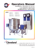
A. SETTING MIXER SYSTEM PRESSURE
1. On the operator panel, switch
“POWER” to on, “MIXER” to on, and
set mixer speed to “STOP”.
2. Turn trim relief stem, item “B”, completely in.
3. Increase the pump pressure by turning “A”
inwards, until gauge “D" reads 1700 psi. The
pressure must be 300 psi higher than the
pump setting.
4. Adjust trim relief “B” outwards until pressure
indicated on gauge “D" begins to drop.
5. Lock the trim relief “B”.
6. Decrease the pump pressure by turning
“A” outwards, until gauge “D" reads 1400 psi
and lock in place.
Figure 2
Part No. 10040R4 15 2018-12-05

INSTALLATION AND OPERATION MANUAL, DIRECT STEAM SINGLE & TWIN MIXER
KETTLE, MODELS DLTM-40 TO DLTM-100 AND DLTM-40-2 TO DLTM-100-2
7.0 MAINTENANCE (Continued)
B. SETTING THE MIXER SYSTEM FLOW
1. On the operator panel, switch “POWER” to on, “MIXER” to on, and set mixer speed to
“FAST”, the maximum speed.
2. Increase or decrease flow to maximum rpm as listed, or less if requested by customer.
Turn in “C” to decrease, turn out to increase.
40 Gallon Kettle 54 RPM
60 Gallon Kettle 48 RPM
80 Gallon Kettle 43 RPM
100 Gallon Kettle 40 RPM
CAUTION: Do not exceed 54 rpm! Decreasing the flow to less than
10 rpm may over centre the swash plate and will damage the pump!
3. Use jam nut to lock adjusting screw when complete.
SETTING THE BRIDGE ACTUATOR
1. On the operator panel, switch “POWER” to on, “MIXER” to on, and set mixer speed to
“STOP”.
2. The pressure reducing valve and associated gauge are located at the back of the
hydraulic unit. Adjust it to 800 psi.
3. The speed of the actuator is controlled by an in-line flow control valve also located at the
back of the unit. There is also a locking set screw provided on the adjusting knob.
4. Using the “RAISE/LOWER” tilt switch on the operator panel, adjust the flow control so
that the stroke is completed at a safe speed.
Part No. 10040R4 16 2018-12-05

INSTALLATION AND OPERATION MANUAL, DIRECT STEAM SINGLE & TWIN MIXER
KETTLE, MODELS DLTM-40 TO DLTM-100 AND DLTM-40-2 TO DLTM-100-2
8.0 TROUBLESHOOTING
EXTREMELY SLOW COOKING TIME
If cooking time is abnormally slow, this may be due to insufficient steam pressure and/or
volume. Determine that pressure on incoming steam line at kettle is within 5 psi of rated kettle
pressure. Note that pressures approaching the rated kettle pressure are liable to set off the
safety relief valve. If required pressure is available to kettle, then volume of steam may not be
sufficient. Minimum 3/4" pipe size is required to the kettle but if the steam generating source is
at a great distance from the kettle, larger pipe will be required. Finally, the core of the steam
supply pipe may have debris or scalants that impede steam flow and will require disassembly
and inspection.
AIR VENTING
A steam trap assembly is plumbed to the exhaust (condensate) side of the kettle(s). The
thermostatic trap is a mechanical device that closes on high temperature and opens when the
temperature drops, allowing water which formed from the condensate to exhaust, but retain
steam under pressure.
The temperatures required for the cooking process to function adequately must be greater than
the boiling point of the liquid food product. The greater the steam pressure used, the higher the
temperature and the quicker the cooking process. For example, steam pressurized at 30 psi
reaches a temperature of 274 degrees Fahrenheit (135 degrees Celsius). Since air is an
unsuitable media through which heat may be transferred, it should be exhausted from the
jacket by opening the pressure relief valve until the air has been completely replaced by
pressurized steam.
In the initial stages of the cooking process, when the steam comes in contact with the cold
kettle bowl surface, it condenses and forms a large amount of water. The condensate water
must be removed from the kettle jacket in order for the kettle to function adequately. The ball
valve located at the base of the kettle jacket may be opened to remove the water. It may be
necessary to repeat this procedure several times depending on the number of batches being
cooked as each batch will create condensate. If the kettle appears to be slow in heating, this
would indicate that there is water in the jacket. Open ball valve and drain. Close valve and
commence operation of kettle.
Part No. 10040R4 17 2018-12-05

INSTALLATION AND OPERATION MANUAL, DIRECT STEAM SINGLE & TWIN MIXER
KETTLE, MODELS DLTM-40 TO DLTM-100 AND DLTM-40-2 TO DLTM-100-2
8.0 TROUBLESHOOTING (Continued)
HYDRAULIC SYSTEM
SOLENOID VALVES FAILED TO OPERATE
1. Voltage too low will not complete the stroke of alternating current (AC) and the solenoid will
burn out the coil.
2. Signal to both solenoids of a double solenoid valve simultaneously. One or both of the
valves will be unable to complete their stroke and burn out. Make certain the electrical
signal is interlocked so that this condition cannot exist.
3. Incorrect voltage or frequency will prevent operation or burn out coil.
4. Foreign matter in valve.
5. Oil too hot.
PUMP
1. Excessive noise caused by vacuum leak in suction line.
2. Misalignment of drive mechanism will cause high noise level in operation.
3. Relief set too high.
4. Return line above fluid level.
5. Reversed rotation.
6. Filter breather plugged.
7. Viscosity of oil too high.
8. Loose or worn pump parts.
9. Air leak at pump shaft seal.
10. Oil too low, drawing in air.
11. Air bubbles in intake oil.
Part No. 10040R4 18 2018-12-05

INSTALLATION AND OPERATION MANUAL, DIRECT STEAM SINGLE & TWIN MIXER
KETTLE, MODELS DLTM-40 TO DLTM-100 AND DLTM-40-2 TO DLTM-100-2
8.0 TROUBLESHOOTING (Continued)
EXCESSIVE WEAR
1. Abrasive material in oil causing wear.
2. Oil viscosity too low.
3. Pump misalignment.
4. Air being drawn in through inlet of pump.
5. System pressure exceeds pump rating.
BROKEN INTERNAL PARTS
1. Lack of oil.
2. Excessive torquing of housing bolts.
3. Solid matter being drawn in from reservoir.
DIRTY OIL
1. Components not cleaned properly after servicing.
2. Air breather left off.
3. Filter dirty or ruptured.
FOAMING OIL
1. Return line not below oil level.
2. Oil contaminated.
3. Suction leak to pump.
MOISTURE IN OIL
1. Water in oil supply.
2. Extreme temperature differential.
Part No. 10040R4 19 2018-12-05

INSTALLATION AND OPERATION MANUAL, DIRECT STEAM SINGLE & TWIN MIXER
KETTLE, MODELS DLTM-40 TO DLTM-100 AND DLTM-40-2 TO DLTM-100-2
8.0 TROUBLESHOOTING (Continued)
OVERHEATING OF SYSTEM
1. Continuous operation at relief setting.
a) Stalling under load.
b) Viscosity of oil too high.
2. Excessive slippage or internal leakage.
a) Fluid too low.
3. System relief valve set too high.
4. Power unit ambient too high.
5. Insufficient volume of cold water supply to oil cooler.
Part No. 10040R4 20 2018-12-05
/