Page is loading ...

Table of Contents Rev. 8/4/2020 P-JIB MANUAL
Table of Contents Copyright 2020 Vestil Manufacturing Co. Page 1 of 14
P-JIB Portable Jib Crane
Instruction Manual
Receiving Instructions
After delivery, remove the packaging from the product. Inspect the product closely to determine whether it
sustained damage during transport. If damage is discovered, record a complete description of it on the bill of lading.
If the product is undamaged, discard the packaging.
NOTE: The end-user is solely responsible for confirming that product design, use, and maintenance comply with
laws, regulations, codes, and mandatory standards applied where the product is used.
Technical Service & Replacement Parts
For answers to questions not addressed in these instructions and to order replacement parts, labels, and
accessories, call our Technical Service and Parts Department at (260) 665-7586. The Department can also be
contacted online at http://www.vestilmfg.com/parts_info.htm
.
Electronic Copies of Instruction Manuals
Additional copies of this instruction manual may be downloaded from https://www.vestil.com/page-manuals.php
.
Vestil Manufacturing Corp.
2999 North Wayne Street, P.O. Box 507, Angola, IN 46703
Telephone: (260) 665-7586 -or- Toll Free (800) 348-0868
Fax: (260) 665-1339
Web: www.vestilmfg.com e-mail: inf[email protected]m
Table of Contents
Page
Signal Words….…………………………………………………………………………………….……….…….…....
2
Safety Instructions……….………………………………………………………………………………………..….....
2
FIG. 1A: P-JIB-2 Exploded View & Bill of Materials……………….……………………………………………….
3, 4
FIG. 1B: P-JIB-2 Specifications……………………………….…….………………………………………………..
5
FIG. 2A: P-JIB-4 Exploded View & Bill of Materials……………...………………………………………………..
6, 7
FIG. 2B: P-JIB-4 Specifications………………………………..…..…………………………….............................
8
FIG. 3: Manual Hydraulic Pump Exploded View & Bill of Materials……………………………………………..
9
Using the Crane………………………………................................................................................……………
10
Using the Hand Pump………………..…………………………………………………………….………………….
10
Air Purging Procedure……………………………………………………………………………..…………….……
11
Boom Length Adjustment………………………………………………………………………………..……….……
11
Record of Satisfactory Condition...................................................................................................................
11
Inspections & Maintenance……………………………..………………………………………….......................…
11-12
Troubleshooting…………………………………………………………………………………………………………..
12
Labeling Diagram……...……………………………….………………………………………………………………..
13
Limited Warranty…...……………………………………………………………………………………………………
14

Table of Contents Rev. 8/4/2020 P-JIB MANUAL
Table of Contents Copyright 2020 Vestil Manufacturing Co. Page 2 of 14
SIGNAL WORDS
This manual classifies personal injury risks and situations that could lead to property damage with SIGNAL
WORDS. A safety message appears with a signal word that describes an improper/dangerous use of the product.
The signal word indicates the seriousness of the injury that could result from the described use.
Identifies a hazardous situation which, if not avoided, WILL result in DEATH or SERIOUS
INJURY. Use of this signal word is limited to the most extreme situations.
Identifies a hazardous situation which, if not avoided, COULD result in DEATH or SERIOUS
INJURY.
Indicates a hazardous situation which, if not avoided, COULD result in MINOR or MODERATE
injury.
Identifies practices likely to result in product/property damage, such as operation that might
damage the product.
SAFETY INSTRUCTIONS
Vestil strives to identify all hazards associated with the use of its products. However, material handling is
dangerous and
no manual can address every risk. The most effective means for preventing accidents is to apply
common sense and sound judgment whenever using this product.
Material handling is dangerous. Improper or careless operation might result in serious personal
injuries sustained by the operator and bystanders. Always apply material handling techniques, including rigging
methods, learned during training and use the product properly:
• Read and understand the entire manual before assembling, using, or servicing the product. Read the manual to
refresh your understanding of proper use and maintenance procedures whenever necessary.
• DO NOT use the crane unless the required ballast is installed. Ballast specifications are provided on pages 5 & 8.
• DO NOT attempt to lift items that weigh more than the capacity of your crane. Capacity decreases as boom length
increases. Capacities of both models appear in FIGS. 1B & 2B on pages 5 & 8.
• DO NOT stand or sit on either the crane or the load. Avoid contact with the casters.
• Stand clear of the load while raising and lowering it.
• ONLY use the crane on even, level, improved surfaces (concrete or asphalt) capable of supporting the combined
weight of the crane and a full capacity load. DO NOT attempt to move the crane up or down sloped surfaces.
• DO NOT perform maintenance on this crane UNLESS it is unloaded and the casters are chocked to prevent
movement. If the crane requires repair, ONLY install manufacturer-approved replacement parts.
• DO NOT begin to raise a load until the load hook is centered above it.
• ALWAYS observe the boom while raising and lowering a load. It should rise smoothly. Watch for binding or jerky
movement and listen for unusual noises.
• DO NOT use the crane unless it is in normal condition. Inspect the unit before each use following the
INSPECTIONS AND MAINTENANCE instructions on p. 9-10 to determine whether it is functioning normally.
• Always watch the load carefully while raising and lowering the boom. Before transporting a load, adjust the load
height to just a few inches above the ground. ONLY transport loads with the boom straight in front of the crane.
• DO NOT continue to move the pump handle back-and-forth if the boom is fully elevated (does not continue to rise).
• Always lower and disconnect the load before leaving the crane unattended.
• Relieve hydraulic pressure by turning the release lever counterclockwise until the boom begins to descend. Lower
the boom completely; then close the release valve.
• DO NOT alter the pressure relief valve setting!
• DO NOT use the crane UNLESS it is labeled as shown in LABELING DIAGRAM on p. 13.
• DO NOT modify this crane in any way. Modifications automatically void the limited warranty and might make the
crane unsafe to use.
• Always make sure that the shackle pin (item 1.13 on p. 3, 4; item 1.13 on p. 6, 7) is secure before applying a load
to the stationary hook. Tighten the screw pin before each use.
Proper maintenance is essential for this product to function properly.
• Follow the INSPECTION AND MAINTENANCE procedures provided on pages 11-12. If repairs are necessary,
only install manufacturer-approved replacement parts.
• Periodically lubricate pivot points.
• Keep the crane clean & dry.


Table of Contents Rev. 8/4/2020 P-JIB MANUAL
Table of Contents Copyright 2020 Vestil Manufacturing Co. Page 4 of 14
P-JIB-2 Bill of Materials
Item
Part no.
Description
Qty.
1
28-002-268
Final assembly without power unit
1
1.1
28-514-208
Weldment, base
1
1.2
28-514-202
Weldment, boom, inner
1
1.3
28-514-203
Weldment, boom, outer
1
1.4
28-514-205
Weldment, mast
1
1.5
28/-514-206
Weldment, outrigger
2
1.6
28-514-207
Weldment, lid
1
1.7
28-612-005
Weldment, outrigger pin
2
1.8
16-132-208
Caster, 8”x2”, swivel
2
1.9
16-132-233
Caster, rigid, GFN-8/2-R
2
1.10
08-145-001
Swivel hook, 2-ton capacity
2
1.11
30-001-011
Leveling jack
2
1.12
21-042-002-001
Hand winch, foldable handle grip
1
1.13
08-145-010
Shackle,
1
/
2
”, 2-ton capacity
1
1.14
99-021-948
Cylinder, hydraulic, 2”x18” stroke
1
1.15
16-025-025
Handle, formed, HT/ergo handle
1
1.16
11105
Hex bolt, grade A, zinc-plated,
3
/
8
”-16x1”
2
1.17
33008
Flat washer, low carbon, USS, zinc-plated,
3
/
8
”
2
1.18
37024
Nylon insert lock nut, grade 2, zinc finish,
3
/
8
”-16
2
1.19
65076
1
/
8
”x1” cotter pin, zinc-plated
4
1.20
99-112-006
Pin, clevis
4
1.21
45286
#11 hitch pin clip,
1
/
8
”x2
5
/
8
”
3
1.22
65127
Cotter pin, zinc-plated,
3
/
16
”-2
4
1.23
11007
Hex bolt,
1
/
4
”- 20UNC x1
1
/
4
”
16
1.24
37018
Nylock nut, grade 2, zinc-finish,
1
/
4
”-20
12
1.25
11324
Hex bolt,
5
/
8
”-11x5
1
/
2
”
1
1.26
33016
Flat washer, low carbon, USS, zinc-plated,
5
/
8
”
1
1.27
37036
Nylock nut, zinc-plated,
5
/
8
”-11
1
1.28
66122
1
/
2
”x4” clevis pin
1
1.29
28-110-001-001
Inner bearing
1
1.30
11101
Hex bolt,
3
/
8
”-16x
1
/
2
”
3
1.31
33622
Split lock washer, carbon steel, medium zinc-finish,
3
/
8
”
3
1.32
47-112-001
Clevis pin, 1” x 3
1
/
4
”
2
1.33
99-027-003
1
/
4
” cable pulley, 3” OD,
1
/
2
” ID
2
1.34
21-112-003
Pin,
1
/
2
” x 1
15
/
16
” retaining clevis
2
1.35
65078
Extended prong cotter pin, zinc finish,
1
/
8
” x 1
1
/
2
”
2
1.36
21-145-013
Specialty hardware, thimble
1
1.37
08-145-045
Clasp hook,
3
/
4
” hook opening
1
1.38
99-145-067
Compression sleeve,
3
/
16
” x 1”
1
2
99-640-013
Assembly, hand pump,
1
/
2
gal. tank
1
3
07-525-006
Assembly, handle
1
4
33004
Flat washer, USS, zinc-plated,
1
/
4
”
4
5
37018
Nylock nut, grade 2, zinc-finish,
1
/
4
”-20
4
6
11009
Hex bolt, gr. A, zinc plated,
1
/
4
”-20 x1
1
/
2
”
4
7
07-025-005
Handle, black rubber, 6”
1

Table of Contents Rev. 8/4/2020 P-JIB MANUAL
Table of Contents Copyright 2020 Vestil Manufacturing Co. Page 5 of 14
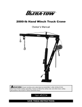
FIG 1B: P-JIB-2 specifications
The inner boom has 4 pin holes spaced 7 inches apart to allow boom length to be adjusted in 7in. increments.
Boom length determines the maximum rated load of the crane, which decreases as boom length increases as
indicated in the table below.
NOTE: Ballast is ALWAYS required whenever the crane is used.
• Add 2,780 lb. (1,264 kg) of ballast to the ballast box BEFORE putting the crane into service.
• If you ordered option P-JIB-BALL-2, then your crane is already equipped with the necessary ballast.
Ballast
box


Table of Contents Rev. 8/4/2020 P-JIB MANUAL
Table of Contents Copyright 2020 Vestil Manufacturing Co. Page 7 of 14
P-JIB-4 Bill of Materials
Item
Part no.
Description
Qty.
1
28-002-269
Final assembly without power unit
1
1.1
28-514-209
Weldment, base
1
1.2
28-514-202
Weldment, boom, inner
1
1.3
28-514-204
Weldment, boom, outer
1
1.4
28-514-205
Weldment, mast
1
1.5
28/-514-206
Weldment, outrigger
2
1.6
28-514-207
Weldment, lid
1
1.7
28-612-005
Weldment, outrigger pin
2
1.8
16-132-171
Caster, 8”x3”, phenolic, swivel
2
1.9
16-132-172
Caster, 8” x 3”, phenolic with fiber, rigid
2
1.10
08-145-001
Swivel hook, 2-ton capacity
1
1.11
30-001-011
Leveling jack
2
1.12
21-042-002-001
Hand winch, foldable handle grip
1
1.13
08-145-010
Shackle,
1
/
2
”, 2-ton capacity
1
1.14
99-021-945
Cylinder, hydraulic, 2
1
/
2
”x18” ram style with clevis mounts
1
1.15
16-025-025
Handle, formed, HT/ergo handle
1
1.16
11105
Hex bolt, grade A, zinc-plated,
3
/
8
”-16x1”
2
1.17
33008
Flat washer, low carbon, USS, zinc-plated,
3
/
8
”
18
1.18
37024
Nylon insert lock nut, grade 2, zinc finish,
3
/
8
”-16
18
1.19
45286
#11 hitch pin clip,
1
/
8
” x 2
5
/
8
”
1
1.20
65127
Cotter pin, zinc-plated,
3
/
16
”-2
4
1.21
11007
Hex bolt,
1
/
4
”- 20UNC x1
1
/
4
”
12
1.22
37018
Nylock nut, grade 2, zinc-finish,
1
/
4
”-20
12
1.23
11324
Hex bolt,
5
/
8
”-11x5
1
/
2
”
1
1.24
33016
Flat washer, low carbon, USS, zinc-plated,
5
/
8
”
1
1.25
37036
Nylock nut, zinc-plated,
5
/
8
”-11
1
1.26
66122
1
/
2
”x4” clevis pin
1
1.27
28-110-001-001
Inner bearing
1
1.28
11101
Hex bolt,
3
/
8
”-16x
1
/
2
”
3
1.29
33622
Split lock washer, carbon steel, medium zinc-finish,
3
/
8
”
3
1.30
11107
Hex bolt, gr. A, zinc finish,
3
/
8
”-16 x 1
1
/
4
”
16
1.31
47-112-001
Clevis pin, 1” x 3
1
/
4
”
2
1.32
99-027-003
1
/
4
” cable pulley, 3” OD,
1
/
2
” ID
2
1.33
21-112-003
Pin,
1
/
2
” x 1
15
/
16
” retaining clevis
2
1.34
65078
Extended prong cotter pin, zinc finish,
1
/
8
” x 1
1
/
2
”
2
1.35
21-145-013
Specialty hardware, thimble
1
1.36
08-145-045
Clasp hook,
3
/
4
” hook opening
1
1.37
99-145-067
Compression sleeve,
3
/
16
” x 1”
1
2
99-640-013
Assembly, hand pump,
1
/
2
gal. tank
1
3
07-525-006
Assembly, handle
1
4
33004
Flat washer, USS, zinc-plated,
1
/
4
”
4
5
37018
Nylock nut, grade 2, zinc-finish,
1
/
4
”-20
4
6
11009
Hex bolt, gr. A, zinc plated,
1
/
4
”-20 x1
1
/
2
”
4
7
07-025-005
Handle, black rubber, 6”
1

Table of Contents Rev. 8/4/2020 P-JIB MANUAL
Table of Contents Copyright 2020 Vestil Manufacturing Co. Page 8 of 14
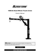
FIG 2B: P-JIB-4 rated loads for specified boom lengths
The inner boom has 4 pin holes spaced 7 inches apart to allow boom length to be adjusted in 7in. increments.
Boom length determines the maximum rated load of the crane, which decreases as boom length increases as
indicated in the table below.
Ballast
box
NOTE: Ballast is ALWAYS required whenever the crane is used.
• Add 3,650 lb. (1,660 kg) of ballast to the ballast box BEFORE putting the crane into service.
• If you ordered option P-JIB-BALL-4, then your crane is already equipped with the necessary
ballast.

Table of Contents Rev. 8/4/2020 P-JIB MANUAL
Table of Contents Copyright 2020 Vestil Manufacturing Co. Page 9 of 14
FIG. 3: MANUAL HYDRAULIC PUMP (99-640-013 REV. B) EXPLODED VIEW & BILL OF MATERIALS
Item
Part no.
Description
Qty.
Item
Part no.
Description
Qty.
1 99-140-005
SUB-ASSEMBLY, MANUAL
PUMP, HAND
1 1.13 99-640-008 SUB-ASSEMBLY, PUMP, ROCKER 1
1.1
99-039-005
BODY, MANUAL PUMP, HAND
1
1.14
99-144-003
WIPER, SOLID PROFILE, PISTON
2
1.2
99-110-007
BEARING, BALL, Ø1/4"
2
1.15
99-042-001
CHAIN, SIDE PLATE, #80
4
1.3 99-146-004
SPRING, COMPRESSION,
INLET CHECK
2 1.16
11484-
01103
PIN, SS GROOVED CLEVIS w/
SNAP RING
4
1.4 99-146-006
SPRING, COMPRESSION,
RETAINER
2 1.17 93257 SHCS 5/16-18 x 1 1/4 4
1.5 99-110-006 BEARING, BALL, Ø3/8" 2 1.18 129169
LOCK WASHER, HI COLLAR, ZINC
PLATED
4
1.6 99-146-005
SPRING, COMPRESSION,
OUTLET CHECK
2 2 99-144-007 O-RING, MANIFOLD, 3" OD 1
1.7 99-116-005
FITTING, HYDRAULIC,
04MORB HOLLOW HEX PLUG
3 3 99-116-001
SUCTION FITTING, MINI
MANIFOLD
1
1.8 99-153-038
FLOW CONTROL, PRES.
COMP., 1.0 GAL.
1 4 99-031-033
ACCESSORIES, NIPPLE, CLOSE
PIPE
1
1.9 99-153-006
VALVE, PRESSURE RELIEF,
210 BAR
1 5 99-031-029 ACCESSORIES, HYDRAULIC 1
1.10 99-153-080
VALVE, CARTRIDGE
w/TOGGLE ARM
1 6 99-145-061
Clamp, Worm Gear Hose, 2 13/16 -
3 3/4
1
1.11
99-144-015
SEAL, U-CUP
2
7
01-023-008
RESERVOIR, OIL
1
1.12
99-041-004
PLUNGER/PISTON, PUMP
2
8
99-616-001
ASSEMBLY, BREATHER
1
*
99-144-001
Replacement seals (kit)
1

Table of Contents Rev. 8/4/2020 P-JIB MANUAL
Table of Contents Copyright 2020 Vestil Manufacturing Co. Page 10 of 14
USING THE CRANE
The floor crane must be used only on improved surfaces (concrete or asphalt) that are even and level.
1) Attach appropriate rigging to the load.
2) Carefully push the crane to the work location;
then low.
3) Position the outriggers and deploy the floor
locks. Outriggers can be rotated out to the
side of the crane to enhance stability. Always
keep the load between the outriggers (don’t
rotate the load beyond the outriggers).
To deploy the floor locks, rotate the hand
cranks clockwise until the feet solidly contact
the floor but do not lift the front casters off of
the ground.
4) Adjust the position of the boom.
a. To raise the boom, move the pump
handle back-and-forth.
b. To lower the boom, slowly turn the
release lever counterclockwise until the
boom begins to lower. To increase the
lowering speed, turn the release lever
further counterclockwise. Close the
release valve when boom adjustment is
complete by turning the release lever
clockwise until the connection is tight.
5) Attach the rigging to the stationary hook at the
end of the boom. If the stationary hook cannot
be lowered enough engage the rigging.
Connect the rigging to the winch hook. The
winch hook capacity is always 800 pounds
(363.6kg), regardless of boom length. Raise
and lower the winch hook by turning the winch
handle in the appropriate direction.
Prevent load swing! Be sure that whichever
hook is used is centered above the load
before raising it. Do not raise the boom or the
winch hook until the hook is centered above
the load.
NOTE: Add the weight of all rigging to the
weight of the load to calculate the net weight
applied to the crane. The net weight must be
less than or equal to the capacity of the crane.
Capacity decreases as the boom is extended
See
FIGS. 1B and 2B on pages 5 and 8.
6) Slowly raise the load until it is a few inches off of the ground.
a. The load should not swing as it rises.
b. The crane should not tip or rock when the load is suspended.
c. If the crane is unstable, lower the load and adjust rigging.
d. The mast rotates to allow the user to move loads to either side of the crane. Rotate the boom slowly when
loaded. Don’t rotate the load beyond the outriggers.
e. Transport the load by pushing the cane slowly and carefully. The load should never be more than a few
inches above the ground during transport.
7) Lower the boom until there is slack in the rigging and disconnect the load from the hook.
USING THE HAND PUMP
The hydraulic pump controls up-and down-movement of the boom. With the lowering lever in the closed
position (rotated clockwise until the connection is snug), move the pump handle back-and-forth to extend the
cylinder. As the cylinder extends, the end of the boom rises and elevates the hooks.
To lower the boom, slowly rotate the release lever counterclockwise. The farther the lever is turned, the faster
the boom lowers. To change load elevation but not lower the load completely, simply close the release valve
when the load is at the desired height, i.e. turn the lever clockwise until the connection is snug.
Stationary
hook
Winch
hook
Floor
lock
Boom
Winch
Raise
Lower
Tank
Pump handle
Fill plug
Release
lever
Hand
pump
Hand
crank
Mast
Outrigger
Ballast box: must be filled
with required weight of
ballast. See page 5 or 8.
Clevis pins

Table of Contents Rev. 8/4/2020 P-JIB MANUAL
Table of Contents Copyright 2020 Vestil Manufacturing Co. Page 11 of 14
RECORD OF SATISFACTORY CONDITION
Before putting the crane into service, describe the appearance and functions of the crane in writing. Include
observations about each part of the crane. Photograph the unit from multiple angles. Include close range
photographs of pivot points and pins, the hydraulic system (cylinder, pump, hoses, and oil tank), hooks, shackles
and shackle pins, floor locks, and casters. Use the crane to lift a test weight. Raise and lower the boom. Include
notes about how much force is required to move the pump handle moves back-and-forth, as well as sounds heard
while the cylinder extends and retracts (boom elevates and lowers). Thoroughly photograph the unit and all labels
applied to it. Add the photographs to the record. This record documents satisfactory condition of the crane.
INSPECTIONS & MAINTENANCE
Compare observations during inspections to your RECORD to determine whether the unit is in satisfactory
condition. DO NOT use the crane unless it is in satisfactory condition. If repairs are necessary, only install
manufacturer-approved replacement parts.
(A) Before each use, inspect the following items:
1) Frame, mast, cylinder brackets (where cylinder attaches to mast and boom), & booms (inner and
outer. Examine each item for damage and severe wear.
2) Cylinder and pump. Check for oil leaks. Raise and lower the boom. Listen for unusual noises and watch
the cylinder. Confirm that it extends and retracts smoothly.
3) Load hook and shackle. Closely examine the load hook and shackle. Make sure that neither is severely
worn, warped, bending or cracking. Confirm that the safety latch (of the hook) operates correctly. Also
inspect the shackle bracket. The bracket should be square and rigid and lack cracks and significant
bends. The pin hole (for the shackle pin) should not be elongated.
4) Shackle and shackle pin. Make sure that the shackle and pin are not bent, cracked, stretched, or
severely worn. The opening in the lifting arm for the shackle should not be stretched, bent or cracked.
5) Inner and outer booms. Confirm that both parts are rigid and square.
6) Repairs. Complete all necessary repairs before returning the crane to service. Make a dated record of all
repairs, adjustments and replacements.
AIR PURGING PROCEDURE
Air can be trapped inside the hydraulic circuit. If this happens, you might notice that the boom feels spongy
when it is raised. Air must be removed from the circuit if this happens.
1. Lower the boom and disconnect the cylinder from the crane by removing the clevis pins. See Diagram on p.
10.
2. Lay the cylinder on a flat surface with the hose on top.
3. Loosen the hose fitting but do not disconnect the hose. Wrap a rag around the fitting.
4. Circulate oil to the cylinder by slowly moving the handle back and forth. Air and oil will sputter from the fitting.
When no more air is present, tighten the fitting and pin the cylinder to the crane.
BOOM LENGTH ADJUSTMENT
To adjust the length of the boom, first use the hand pump to raise the boom to make it level. Remove the
hitch pin and pull out the clevis pin. The inner boom is now free and can be pulled or pushed. Align the
appropriate holes in the inner and outer booms to produce the desired boom configuration; then reinstall the
pins.
Hitch pin
Clevis pin

Table of Contents Rev. 8/4/2020 P-JIB MANUAL
Table of Contents Copyright 2020 Vestil Manufacturing Co. Page 12 of 14
(B) Inspect the following at least once per month:
1) Oil level. Lower the boom completely. Oil should be within ¾in. of the top of the tank with the boom in the
fully lowered position. See Subpart C, “Yearly inspection”.
2) Hoses. Check for cuts, kinks, and other damage. Confirm that the ends of the hose are firmly fastened to
the pump and the cylinder.
3) Hardware. Check the integrity of all nuts, bolts, and pins. Replace any item that is damaged.
4) Casters. Move the crane a short distance. Determine whether each caster is loose, severely worn, or
damaged. Clean the casters. Replace casters that do not roll smoothly or are bent or cracked.
5) Winch, cable, and pulleys. Examine the cable for frays, broken strands, kinks, etc. Make sure that the
cable clamp (connects the hook to the cable) is secure. Make sure that all pulleys operate satisfactorily.
Confirm that hardware is in satisfactory condition.
6) Labels. Check all labeling. The crane should be labeled as shown in the LABELING DIAGRAM.
(C) Regularly inspect the hydraulic oil (at least twice per year)
In addition to the inspections described in parts A and B, check the hydraulic fluid at least twice per year.
Change the oil immediately if it darkens, becomes gritty, or turns a milky color (indicating the presence of water).
Replace the hydraulic fluid with anti-wear hydraulic oil of viscosity grade 150 SUS at 100°F, (ISO 32 at 40°C).
Examples of proper hydraulic fluid are AW 32 and HO 150 hydraulic oil, and non-synthetic transmission fluid. You
may use a synthetic transmission fluid if you flush the system with the synthetic fluid before filling the reservoir.
TROUBLESHOOTING
Refer to Manual Hydraulic Pump Exploded View and Bill of Materials on page 9.
Issue
Explanation
Remedy
1. Cylinder does not
extend when I
move the handle
a. Too much weight applied (load
exceeds capacity).
b. Too little oil in hydraulic system.
c. Pinched hydraulic hose.
d. Relief valve pressure setting too
low.
a. Remove enough of load that weight of load is
within capacity.
b. Add oil until level is within one inch of top of
reservoir.
c. Correct as appropriate.
d. Increase pressure setting as necessary, but
NEVER to more than 3,000psi
2. A lot of force is
required to move
the handle
e. Autoshifter valve stuck in
deactivated position.
f. Load exceeds capacity.
e. Remove port plug from port marked “UL” (on
manifold); then remove piston. Inspect piston
and springs
f. Reduce load to be within capacity
3. Cylinder extends
only when
unloaded or
handle pumped
rapidly. -OR-
I can pump the
handle but the
cylinder does not
move.
g. Pump is air locked.
h. Debris on seat of inlet check
valve.
i. Pressure setting of relief valve
needs adjustment.
j. Debris on seat of relief valve.
g. Remove air from the pump. See Air Purging
Procedure on p. 11.
h. Remove inlet check valve and clean debris
from valve seat (the bottom of the cavity in
pump body that valve fits into).
i. Increase pressure setting as necessary, but
NEVER more than 3,000psi.
j. Remove relief valve and clean debris from
valve seat in pump body.
4. Cylinder extends
during down stroke
of handle, but
lowers during
return stroke.
k. Outlet check valve stuck in open
position.
k. Remove, disassemble, clean (with mineral
spirits or kerosene), reassemble and reinstall
outlet check valve assemblies.
5. Have to keep
pumping handle to
maintain cylinder
extension
l. Outlet check valve allowing oil to
return to pump chamber.
m. Release valve allowing oil to leak
back to the tank.
l. Remove both outlet check valves. Clean
valves. Score bottom of chamber for ball
bearing.
m. Remove release valve assembly, inspect,
clean, & repair as necessary
6. Pump feels
spongy or cylinder
extends in jerks
n. Oil level is low
o. Air present in pump and/or
cylinder
n. Add oil until within 1in. of top of reservoir.
o. Purge air by following Air purging procedure
on p. 11.
7. Cylinder retracts
very slowly
p. Flow control valve obstructed
p. Remove valve and inspect for debris or non-
operating spool
8. Cylinder retracts
too rapidly
q. Flow control valve obstructed or
not moving freely
q. Remove valve and inspect for debris or non-
operating spool

Table of Contents Rev. 8/4/2020 P-JIB MANUAL
Table of Contents Copyright 2020 Vestil Manufacturing Co. Page 13 of 14
The unit should be labeled as shown in the diagram. However, label content and location are subject to
change so your product might not be labeled exactly as shown. Compare this diagram to your RECORD OF
SATISFACTORY CONDITION. Replace all labels that are damaged, missing, or not easily readable (e.g. faded).
Order replacement labels by contacting the PARTS DEPARTMENT online at
http://www.vestilmfg.com/parts_info.htm or by calling (260) 665-7586 and asking for the PARTS DEPARTMENT
.
LABELING DIAGRAM
E: Label 287 (on counterweight; model,
serial number, & capacity)
D: Label 586 (on counterweight; use-related warnings)
C: Label 206 (hydraulic fluid specifications)
A
B
C
D
A: Capacity information
B: Boom capacities at various lengths
(label is specific to P-JIB-2 and P-JIB-4)
Capacity at
Arm length Max. Height Pounds
24
3
/
8
” ___” _____ lb.
31
3
/
8
” ___” _____ lb.
38
3
/
8
” ___” _____ lb.
43
3
/
8
” ___” _____ lb.
ALL CAPACITIES ARE
FROM STATIONARY HOOK
ONLY.
WINCH HOOK IS 800LB.
CAPACITY
E
F
G
F: Use instructions
LOCATE OUTRIGGERS AND
ENGAGE LEVELING JACKS
BEFORE LIFTING LOAD.
G: Floor lock info.
Model: LJ-17
LEVELING JACK. 17” TRAVEL
Made in China

Table of Contents Rev. 8/4/2020 P-JIB MANUAL
Table of Contents Copyright 2020 Vestil Manufacturing Co. Page 14 of 14
LIMITED WARRANTY
Vestil Manufacturing Corporation (“Vestil”) warrants this product to be free of defects in material and workmanship
during the warranty period. Our warranty obligation is to provide a replacement for a defective, original part covered
by the warranty after we receive a proper request from the Warrantee (you) for warranty service.
Who may request service?
Only a warrantee may request service. You are a warrantee if you purchased the product from Vestil or from an
authorized distributor AND Vestil has been fully paid.
Definition of “original part”?
An original part is a part used to make the product as shipped to the Warrantee.
What is a “proper request”?
A request for warranty service is proper if Vestil receives: 1) a photocopy of the Customer Invoice that displays the
shipping date; AND 2) a written request for warranty service including your name and phone number. Send requests
by one of the following methods:
US Mail Fax Email
Vestil Manufacturing Corporation (260) 665-1339 info@vestil.com
2999 North Wayne Street, PO Box 507 Phone Enter “Warranty service request”
Angola, IN 46703 (260) 665-7586 in subject field.
In the written request, list the parts believed to be defective and include the address where replacements should be
delivered. After Vestil receives your request for warranty service, an authorized representative will contact you to
determine whether your claim is covered by the warranty. Before providing warranty service, Vestil will require you to
send the entire product, or just the defective part (or parts), to its facility in Angola, IN.
What is covered under the warranty?
The warranty covers defects in the following original, dynamic parts: motors, hydraulic pumps, motor controllers,
and cylinders. It also covers defects in original parts that wear under normal usage conditions (“wearing parts”), such
as bearings, hoses, wheels, seals, brushes, and batteries.
How long is the warranty period?
The warranty period for original dynamic components is 90 days. For wearing parts, the warranty period is 90
days. Both warranty periods begin on the date Vestil ships the product to the Warrantee. If the product was
purchased from an authorized distributor, the periods begin when the distributor ships the product. Vestil may, at its
sole discretion, extend a warranty period for products shipped from authorized distributors by up to 30 days to account
for shipping time.
If a defective part is covered by the warranty, what will Vestil do to correct the problem?
Vestil will provide an appropriate replacement for any covered part. An authorized representative of Vestil will
contact you to discuss your claim.
What is not covered by the warranty?
The Warrantee (you) is responsible for paying labor costs and freight costs to return the product to Vestil for
warranty service.
Events that automatically void this Limited Warranty.
• Misuse;
• Negligent assembly, installation, operation or repair;
• Installation/use in corrosive environments;
• Inadequate or improper maintenance;
• Damage sustained during shipping;
• Collisions or other accidents that damage the product;
• Unauthorized modifications: Do not modify the product IN ANY WAY without first receiving written authorization
from Vestil.
Do any other warranties apply to the product?
Vestil Manufacturing Corp. makes no other express warranties. All implied warranties are disclaimed to the extent
allowed by law. Any implied warranty not disclaimed is limited in scope to the terms of this Limited Warranty. Vestil
makes no warranty or representation that this product complies with any state or local design, performance, or safety
code or standard. Noncompliance with any such code or standard is not a defect in material or workmanship.
/