DELTA DORE CS 8000 TYXAL+ Installation guide
- Category
- Security access control systems
- Type
- Installation guide
This manual is also suitable for

Alarm system
User guide
EN
CS 8000 TYXAL +
* Up to 10 years valid under the condions of use specied in the installaon instrucons and the General Condions of Sale.

EN
- 2 - - 3 -
1. How does your alarm system work?................................................................................................... 6
1.1 Presentation .............................................................................................................................................................. 6
1.2 Products of the range................................................................................................................................................ 7
1.3 Home automation functions ...................................................................................................................................... 9
1.4 X3D wireless transmission ...................................................................................................................................... 10
1.5 System surveillance ................................................................................................................................................10
1.6 Tamper alarm .......................................................................................................................................................... 10
1.7 Battery life ............................................................................................................................................................... 10
1.8 Immunity to radio scrambling .................................................................................................................................. 10
1.9 Access codes .......................................................................................................................................................... 11
1.10 Standard EN 50131 .............................................................................................................................................. 11
1.11 Operation by independent zone ............................................................................................................................ 12
2. Alarm control unit installation ........................................................................................................... 14
2.1 Alarm control unit location ...................................................................................................................................... 14
2.2 Mounting ................................................................................................................................................................. 14
3. Activation with a CLT 8000 TYXAL+ touch screen keypad ............................................................. 15
3.1 Activating for the first time ....................................................................................................................................... 15
3.2 Maintenance mode ................................................................................................................................................ 16
3.2.1 Entering maintenance mode..................................................................................................................... 16
3.2.2 Exiting maintenance mode ....................................................................................................................... 16
3.2.3 Simplify the activation ...............................................................................................................................17
3.3 Adding products ...................................................................................................................................................... 18
3.3.1 Associating a product of the alarm range ................................................................................................. 18
3.3.2 Exiting the "Add product" mode ................................................................................................................ 19
3.4 Access codes (Create - Change - Delete) .............................................................................................................. 20
3.4.1 General ..................................................................................................................................................... 20
3.4.2 Creating or changing a code from the installer code ................................................................................ 21
3.4.3 User code access levels ........................................................................................................................... 21
3.4.4 Changing a user code from the user code ............................................................................................... 21
3.5 Personalising the installation ................................................................................................................................. 22
3.5.1 Setting the clock ....................................................................................................................................... 22
3.5.2 Language selection .................................................................................................................................. 22
3.5.3 Download .................................................................................................................................................. 22
3.5.4 Weekly programming ................................................................................................................................ 23
3.5.7 Naming the products ................................................................................................................................ 25
3.5.8 Activate/deactivate tamper alarm ............................................................................................................. 26
3.5.9 Entry timer on intrusion detectors (immediate/delayed triggering) ........................................................... 26
3.5.10 Button lighting ......................................................................................................................................... 26
3.5.11 Button beeps .......................................................................................................................................... 27
3.5.12 Screen brightness................................................................................................................................... 27
3.5.13 System status ......................................................................................................................................... 27
3.5.14 Button sensitivity ..................................................................................................................................... 27
3.5.15 Sound levels ........................................................................................................................................... 28
3.5.16 Exit time for the installation ..................................................................................................................... 29
3.5.17 Last exit to be used ................................................................................................................................ 29
3.5.18 Confirmation ON/OFF ............................................................................................................................ 30
3.5.19 Maintenance siren .................................................................................................................................. 30
3.5.20 Anti-jamming ........................................................................................................................................... 31
3.5.21 Defect management ............................................................................................................................... 31
3.5.22 Creating phone numbers ........................................................................................................................ 32
3.5.23 Editing or deleting a phone number ........................................................................................................ 33
3.5.23 Remote monitoring ................................................................................................................................. 33
3.5.24 Incoming calls ......................................................................................................................................... 35
3.5.25 Auto attendant ........................................................................................................................................ 35
3.5.26 Maintenance call ..................................................................................................................................... 36
3.5.27 SMS alert to relatives ............................................................................................................................. 36
Contents
Warnings
We recommend you read this installation guide carefully before any use.
• The battery life specified is for normal use.
• It is advisable to use a touch screen keypad (CLT 8000 TYXAL+) for all configuration operations on
the installation.
Glossary
PSTN: Public Switched Telephone Network.
A PSTN telephone transmitter is connected to the
telephone line of your home.
GSM: Global System for Mobile communications.
A GSM telephone transmitter is connected to a wireless
phone network.
Tamper alarm: the products are protected against
being opened or dislodged.
If a burglar tries to open or dislodge one of the products,
a message is sent to the alarm control unit which triggers
its indoor siren, and the installation's sirens (indoor or
outdoor siren, telephone transmitter).
The tamper alarm is permanently activated even if the
system is off. It only generates the external siren noise if
the system is on.
It can be deactivated via a CLT 8000 TYXAL+ touch
screen keypad.
To open a product, you must switch the system to
Maintenance mode.
Discreet emergency alarm: the "discreet emergency
alarm" function needs a telephone transmitter.
It can warn the outside of any aggressor by a discreet
call.
Emergency alarm with siren: the "emergency alarm
with siren" function immediately
warns the neighbours by triggering both a phone call
via a transmitter as well as the sound of the associated
sirens.
Maintenance mode: Maintenance mode is used
to perform the activation, maintenance and
diagnostic operations. The system must be off to access
this mode.
The alarm control unit is switched to maintenance mode
by a keypad (touch screen or simple), a remote control or
a badge reader.
Add product mode: This mode is used to associate new
products with the system. It can only be accessed
via the Maintenance mode.
Restricted code: a user code can be of the restricted
type, that is to say that it only gives access to the On and
Off commands of the zones with which it is associated
(e.g. maintenance personnel, delivery, etc.).
Problem beeps: They report that an action is rejected
by a series of beeps. You must consult the events on the
touch screen keypad (Info menu) to determine the nature
of the problem.
Warning beeps: They report that an alarm or automatic
operation is imminent through a series of beeps at
intervals. After the warning period, the alarm control unit
siren can be set off.
: Symbol meaning that the operation described by
the guide must be carried out in Maintenance
mode.

EN
- 4 - - 5 -
7. Video Function .................................................................................................................................... 62
7.1 Associate the video function with the system ......................................................................................................... 62
8. Associate home automation functions............................................................................................. 64
8.1 Associating a control system receiver (e.g. TYXIA 6410) ....................................................................................... 64
8.2 Associating a roller shutter receiver (e.g. TYXIA 5730) .......................................................................................... 64
8.3 Associating a TYMOOV wireless roller shutter motor ............................................................................................. 65
• You want the roller shutters to close automatically when the alarm system is switched on ........................... 65
8.4 You want to control the opening of roller shutters if smoke is detected .......................................................65
9. Associating a REP TYXAL+ repeater ............................................................................................... 66
10. Deleting products ............................................................................................................................. 67
10.1 From the CS 8000 TYXAL+ alarm control unit ..................................................................................................... 67
10.1.1 Delete the control devices ...................................................................................................................... 67
10.1.2 Deleting all products except the sirens ................................................................................................... 67
10.1.3 Removing all products ............................................................................................................................ 67
10.1.4 Deleting the access codes ...................................................................................................................... 67
10.2 From a CLT 8000 TYXAL+ touch screen keypad .................................................................................................. 68
10.2.1 Deleting a product .................................................................................................................................. 68
10.2.2 Deleting all products except the outdoor siren ....................................................................................... 68
10.2.3 Removing all products ............................................................................................................................ 68
11. Restoring factory settings (Initialisation) ....................................................................................... 69
11.1 Initialising the CS 8000 TYXAL+ alarm control unit ............................................................................................. 69
11.2 Initialising the CLT 8000 TYXAL+ touch screen keypad ....................................................................................... 69
11.3 Initialising a TL 2000 TYXAL+ remote control ....................................................................................................... 69
11.4 Initialising a CLS 8000 TYXAL+ simple keypad .................................................................................................... 69
11.5 Initialising a LB 2000 TYXAL+ badge reader ........................................................................................................ 70
11.6 Initialising a CLE 8000 TYXAL+ outdoor keypad .................................................................................................. 70
11.6.1 Deleting the association with the alarm system ..................................................................................... 70
11.6.2 Deleting the wireless association with the control systems .................................................................... 70
11.7 Initialising a motion detector ................................................................................................................................. 70
11.8 Initialising a door/window magnetic contact .......................................................................................................... 71
11.9 Initialising a TTRTC TYXAL+ , TTGSM or TYDOM 2.0 telephone transmitter ...................................................... 71
11.9.1 Initialising the access codes ................................................................................................................... 71
11.9.2 Full initialisation of the transmitter .......................................................................................................... 71
11.10 Initialising a mains power failure detector ........................................................................................................... 72
11.11 Initialising an outdoor siren ................................................................................................................................. 72
11.12 Full initialisation from a touch screen keypad ..................................................................................................... 72
11.13 Initialising a detector ......................................................................................................................................... 72
12. Summary of LEDs, buttons and audible signals ........................................................................... 73
12.1 LED operation ....................................................................................................................................................... 73
12.2 Button operation.................................................................................................................................................... 73
12.3 Audible signals ...................................................................................................................................................... 74
13. Replacing the batteries .................................................................................................................... 75
14. Technical characteristics ................................................................................................................. 77
15. Troubleshooting ................................................................................................................................ 78
Contents
3.5.28 SIM card ................................................................................................................................................ 37
3.5.29 Privacy .................................................................................................................................................... 37
3.6 Zone management .................................................................................................................................................. 38
3.6.1 Assigning a product to a zone (1 to 8) ...................................................................................................... 38
3.6.2 Naming the zone ...................................................................................................................................... 38
3.6.3 Viewing the zones .....................................................................................................................................39
3.6.4 Deleting a product from a zone ................................................................................................................ 39
3.6.5 Deleting a zone ......................................................................................................................................... 40
3.6.6 Associating a zone with the pre-alarm function ........................................................................................ 40
3.6.7 Creating a common zone ......................................................................................................................... 41
3.6.8 Assigning a restricted access code to a zone .......................................................................................... 41
3.7 Door chime function ................................................................................................................................................ 42
3.8 Testing the installation ............................................................................................................................................. 42
3.8.1 Test a detector (DO, MDO, DOI PVC, DOS, DMB, DMBD, DME, DMBE, DVR TYXAL+ ) ........................42
3.8.2 Test a DMBV TYXAL+ detector ................................................................................................................ 43
3.8.3 Testing the sirens (Si TYXAL+ or SEF TYXAL+, CS 8000 TYXAL+
alarm control unit, TTRTC TYXAL+ , TTGSM, TYDOM 2.0 telephone transmitter) ........................................... 43
3.8.4 Testing a DCP TYXAL+ impact detector or a DCS TYXAL+ , DF or DU detector .................................... 44
3.8.5 Test under operating conditions ................................................................................................................ 44
3.9 Activating/Deactivating a product ............................................................................................................................ 46
4. Activation without a CLT 8000 TYXAL+ touch screen keypad ........................................................ 47
4.1 Activating for the first time ....................................................................................................................................... 47
4.2 Maintenance mode ................................................................................................................................................. 48
4.2.1 Entering maintenance mode..................................................................................................................... 48
4.2.2 Exiting maintenance mode ....................................................................................................................... 49
4.3 Adding a product ..................................................................................................................................................... 50
4.3.1 Step 1: Switch the alarm control unit to maintenance mode .................................................................... 50
4.3.2 Step 2: Set the alarm control unit to “Add product” mode. ........................................................................ 50
4.3.3 Step 3: Confirm on the product to be associated ..................................................................................... 51
4.3.4 Step 4: Exit the "Add product" mode ........................................................................................................ 52
4.4 Access codes (Create - Change - Delete) ............................................................................................................. 53
4.4.1 General .................................................................................................................................................... 53
4.4.2 Creating a user code ................................................................................................................................ 53
4.4.3 Changing an access code ........................................................................................................................ 54
4.4.4 Deleting a user access code .................................................................................................................... 54
4.4.5 Deleting all access codes ......................................................................................................................... 55
4.5 Personalising the products ...................................................................................................................................... 55
4.5.1 Entry timer on intrusion detectors (immediate/delayed triggering) ........................................................... 55
4.6 Zone management .................................................................................................................................................. 56
4.6.1 Assigning a product to a zone (1 to 8) from a CLS 8000 TYXAL+ simple keypad .................................. 56
4.6.2 Assigning a product to a zone (1 to 2) from a TL 2000 TYXAL+ remote control .....................................57
4.6.3 Assigning a product to a zone (1 to 2) from a LB 2000 TYXAL+ badge reader....................................... 57
4.7 Testing the installation ............................................................................................................................................. 58
4.7.1 Test a detector (DO, MDO, DOI PVC, DOS, DMB, DMBD, DMBV, DME, DMBE, DVR TYXAL+ ) ............ 58
4.7.2 Testing the sirens (Si TYXAL+ or SEF TYXAL+ sirens, TYXAL+
CS 8000 alarm control unit, TTRTC TYXAL+ , TTGSM, TYDOM 2.0 telephone transmitter) ............................ 58
4.7.3 Testing the wireless range and operation of a product ............................................................................. 58
5. Configuring a CLE 8000 TYXAL+ outdoor keypad .......................................................................... 59
5.1 Configure the type of control system controlled ..................................................................................................... 59
5.2 Associate the keypad with a control system .......................................................................................................... 59
5.3 Personalise the access code or codes for the control system control ................................................................... 59
6. Configuring a TL 2000 TYXAL+ remote control ................................................................................ 60
6.1 Configuring buttons 1 and 2 .................................................................................................................................... 60
6.2 Associating buttons 1 and 2 with a control system receiver ................................................................................... 61

EN
- 6 - - 7 -
1.2 Products of the range
CLT 8000 TYXAL+ touch screen keypad
Essential complement to the alarm control unit, it is used for all
the control actions of the installation.
Wall-mounted, it informs you of the system's status.
With its access code, it enables the system to be activated or
deactivated totally or by zone.
It shows the last events occurring, the indoor and outdoor
temperature (if an outdoor siren is associated with the control
unit) and is used to personalise the system.
CLS 8000 TYXAL+ simple keypad and LB 2000 TYXAL+
badge reader
Wall-mounted, they enable the system to be activated or
deactivated totally or by zone.
TL 2000 TYXAL+ 4-button remote control
It enables the system to be activated or deactivated totally or by
zone.
Two buttons (1 and 2) can be configured for control
of the alarm by zone, the triggering of a
discreet or audible emergency alarm or control of control
systems
(e.g. garage door).
DMB, DMBD, DMBV, DME or DMBE TYXAL+ motion
detectors
Wall-mounted, they detect any person moving in the room
where they are installed and report this to
the alarm control unit.
DO, MDO, DOI PVC, DOS, DCP or DVR TYXAL+ door/window
magnetic contacts
When installed on an opening, (door or window), they report
any intrusion to the control unit.
DFR, DU, DF or DCS TYXAL+ detectors
They report any technical defect to the alarm control unit:
smoke detection, water leaks, mains power failure, etc.
TTRTC, TTGSM TYXAL+ or TYDOM 2.0 telephone
transmitters
Associated with the control unit, they trigger a call cycle for any
event occurring on the installation.
Max. number of products for an installation:
You can install up to 50 products (intrusion and technical detectors, sirens, keypads or remote controls).
Some product types are restricted in number: 1 telephone transmitter (TTRTC TYXAL+ , TTGSM or TYDOM 2.0), 4
video motion detectors (DMBV TYXAL+) and 1 repeater ( REP TYXAL+ ).
1.1 Presentation
The alarm system is used to monitor a home by means of intrusion detectors (infrared, dual technology or door/window
magnetic contacts, etc.) and technical defect detectors (smoke, water, mains power failure, etc.)
The system is activated or deactivated by means of a remote control, a keypad or badge reader, a telephone transmitter
or according to the weekly programming of a touch screen keypad, smartphone or tablet via the TYDOM application.
The alarm is signalled:
- by the internal siren of the control unit,
- and/or by an associated siren (indoor or outdoor),
- and/or using an associated transmitter, to another telephone or a remote monitoring operator,
The system is fully battery operated. The battery life is 10 years (depending on the conditions of use).
Your alarm and home automation system can be controlled remotely (up to 5 control systems, 4 scenarios, 1 heating
channel) from a telephone transmitter or the iTYDOM application (see transmitter guide).
TTRTC
TYXAL +
CLE 8000
TYXAL +
MDO
TYXAL +
DOI PVC
TYXAL +
DO
TYXAL +
DMB
TYXAL +
DMBD
TYXAL +
DMBV
TYXAL +
DME
TYXAL +
DMBE
TYXAL +
DFR
TYXAL +
CS 8000
TYXAL +
Si
TYXAL +
SEF
TYXAL +
TTGSM
TYXAL +
DCP
TYXAL +
DOS
TYXAL +
DU
TYXAL +
DVR
TYXAL +
CLT 8000
TYXAL +
TL 2000
TYXAL +
CLS 8000
TYXAL +
REP
TYXAL +
TYDOM 2.0
DF
TYXAL +
LB 2000
TYXAL +
DCS
TYXAL +
Application iTYDOM
TYDOM 1000
1
Volets
Alarme
Autres
Eclairages
Garage
Scénarios
Chauffage
Portail
Pièces
To control
To detect
To repeat
To alert/signal
To centralize
Technical detectorsIntrusion detectors
1. How does your alarm system work?

EN
- 8 - - 9 -
1.3 Home automation functions
The home automation functions are used to combine the "Alarm" application
with the other "Thermal" or "Control system" applications.
Examples
• You want to switch off the heating if a window is opened:
The door/window magnetic contacts can be associated, for example, with an
energy manager of the CALYBOX 2020 WT, TYBOX 2010 WT or 2020 WT
type.
• You want to delay the alarms, status of the system or the operations
for activating or deactivating the system via an offset lighting:
You can associate a TYXIA 6410 receiver.
• You want to control the opening of roller shutters if smoke is detected
or
you want the roller shutters to close automatically when the alarm
system is activated:
You can associate TYXIA 4630 or 4730 roller shutter receivers or a wireless
Rollia X3D motor.
TYXIA 6410
X3D control
system receiver
Scenarios
Settings
11.5°C Mon. 23 September
18:28
Others
Cons. Thermique
Shutters
Ouvrant
31
Calendar
Hot water
ROLLIA X3D
Roller shutter motors
CALYBOX 2020 WT
Energy manager
1. How does your alarm system work?
DMB TYXAL+
DFR TYXAL+
MDO
TYXAL+
SEF TYXAL+
CS 8000 TYXAL+
TTRTC TYXAL+
CLT 8000
TYXAL+
TL 2000
TYXAL+
SEF TYXAL+ outdoor siren
The loud sound of the siren will alert your neighbours in the
event of intrusion.
It is equipped with flash lighting to make visual location easier.
It is designed to be fitted outside your home, on a wall for
instance.
Si TYXAL+ indoor siren
The loud sound of the siren will cause the burglar to flee
in the event of intrusion.
REP TYXAL+ repeater
Used when wireless propagation can be affected
(distance, disrupted environment, nature of partitions, etc.),
it can repeat the radio signal to remote products.
Roller shutter motor (with obstacle detection)
If a break-in is attempted on the shutter, this
is reported to the alarm control unit.
TYDOM 4000, TYDOM 1.0 or 2.0, iTYDOM application
This activates or deactivates the system by zone or totally, and
is used to view the events occurring on the installation.
Installation example

EN
- 10 - - 11 -
1.9 Access codes
The access codes (6 digits) are recorded in the alarm control unit. You configure the access codes once with the
CLT 8000 TYXAL+ touch screen keypad and the other products (keypads or transmitters) recognise these codes
automatically. You no longer need to configure the codes on each product.
We recommend that you keep the access codes confidential (6 digits).
Avoid codes such as “date of birth” or obvious series of digits (e.g. “222222”, “234567”, etc).
You have:
- 1 “installer” code (123456 on activation). It is strongly recommended that you change this code.
- 10 “user” (or “restricted”) codes with 6 digits, which enable control and configuration actions.
You must create one at least.
• The installer code enables all the control and configuration actions for the system.
From the installer code, you can create or remove all codes (user and installer).
• The user code enables the control actions and a few configuration actions.
It can be changed by the user.
• Restricted code: a user code can be of the restricted type, that is to say that it only gives access to the on and off
commands of the zones with which it is associated (e.g. maintenance personnel, delivery, etc.).
1.4 X3D wireless transmission
The X3D wireless transmission used by the alarm enables the system's products to communicate with each other on two
frequencies: 868.95 MHz and 868.30 MHz
Two different propagation modes ensure that information sent by the detectors will reach the alarm control unit, whatever
the environment.
The wireless range of each product of the system is 200 to 300 metres outside.
The X3D protocol is the language used by the
products to communicate between themselves. It ensures
secure digital transmission and the
compatibility of the system with all products
using the X3D protocol.
To eliminate the risks of fraud by copying the
radio code, each order to switch the surveillance on and off uses
a different encrypted message.
The security of the messages sent by the products
is provided by a unique code assigned in the factory
for each of the products (more than 1 million possibilities).
1.5 System surveillance
Supervision
To ensure that all the system’s products are in working order, the range is permanently
monitored.
Each product regularly sends a radio message to the alarm control unit to confirm that it is working correctly.
If the alarm control unit is no longer receiving messages from a product, it triggers a “Monitoring” defect.
As soon as you use a keypad or a remote control, the alarm control unit will signal the problem by a problem beep.
1.6 Tamper alarm
The products of the TYXAL+ alarm range are protected against sabotage attempts
(apart from remote controls, MDO, DOI PVC TYXAL+ door/window magnetic contacts and the technical detectors):
- protection against the inopportune opening and removal for the detectors, the keypads, the alarm control unit, the sirens
and the telephone transmitters.
- protection against opening for the DU and DCP TYXAL+ .
If a burglar tries to open or dislodge one of the products, a message is sent to the alarm control unit which triggers its
indoor siren and warns the installation sirens (indoor or outdoor siren, telephone transmitter).
The tamper alarm is permanently activated even if the system is off.
It can be deactivated via a CLT 8000 TYXAL+ touch screen keypad.
To open the products without triggering the alarm, you must set the alarm control unit to
maintenance mode.
1.7 Battery life
The DELTA DORE alarm system is powered by battery.
It is designed to operate for 10 years (depending on the conditions of use) without needing to be changed.
1.8 Immunity to radio scrambling
The DELTA DORE alarm system has a scrambling signal detection function.
In the event of a scrambling attempt, a message is memorised in the history.
Important:
- the radio waves cross the walls but lose power
depending on the materials used,
- you must be careful especially when the waves
must pass through thick concrete walls or metal
structures,
- the wireless range may therefore be reduced to
ten or so metres within the home.
1. How does your alarm system work?
1.10 Standard EN 50131
The DELTA DORE alarm system complies with European standard EN 50131 and ensures quality and reliability for you:
- EN50131-1, EN50131-3 Grade 2
- EN50130-5, Environment Class II

EN
- 12 - - 13 -
• Pre-alarm zone
Associated with a detector, the pre-alarm zone is used
to dissuade intrusion attempts.
Example: An outside detector reports a presence to the
control unit, which triggers a signalling on the outdoor siren (visual
and/or audible).
The detectors associated with a pre-alarm zone are
automatically switched to immediate triggering.
• Common zone
The common zone is directly dependent on the status of the other
zones.
It switches:
- on when all the zones are activated.
- off when at least one zone shuts down.
Example: an office platform.
Zones 1 and 4 are activated.
Zones 2, 3, 5, 6, 7 are deactivated.
The common zone is deactivated.
When the office closes, when the last occupant activates their
zone, the common zone is automatically activated.
When the office opens, and when the first occupant deactivates
their zone, the common zone is automatically deactivated.
• Other zone
A detector that will not be assigned to a specific zone
is automatically located in an "Other" zone.
It thus allows you to identify a detector that has not been assigned
to a zone.
Example: your installation is divided into 2 surveillance zones.
If you assign the initial products to zone 1, the other
products are automatically assigned to the "Other" zone.
By assigning the products to zone 2, the "Other" zone will
disappear.
1
2
3
4
7
6
5
Common zone
1
2
3
4
7
6
5
Common zone
1.11 Operation by independent
zone
The zones are used to protect part of the home.
The management of these zones is fully separate.
One or more zones can be on at the same time (e.g. garage
and first floor zones on, ground floor zone off).
• Perimeter protection
Provided by door/window magnetic contacts, it prevents
risks of intrusion by the entries (doors, windows).
It enables you to protect your home when you are present
(example 1: night, example 2: a domestic animal is present).
You can assign a zone to perimeter protection.
• With a separate garage
Set up a zone for the garage.
• For homes with several floors
Set up a zone per floor:
- a basement with a garage and the home upstairs,
- a ground floor used during the day and bedrooms upstairs,
- a home upstairs and a shop below...
1. How does your alarm system work?
• Once the installation detectors are associated, you can organise them into operating zones
(up to 8 zones).
A zone is only active if at least one detector is assigned to it,
A detector can only belong to one zone,
A detector that is not assigned to a specific zone is located in the zone known as "other zone".
• With the remote control or the badge reader, you can activate zones 1 and 2.
A keypad (CLS 8000 TYXAL+ or CLT 8000 TYXAL+ ) allows you to control up to 8 zones.
• You can assign a restricted access code to each zone.
Perimeter protection
Protection of a separate garage
Protection of a floor during the day and the ground
floor during the night
Zone 1
garage
Zone 1
floor
Zone 2
Ground floor
Zone 1
perimeter
of the home

EN
- 14 - - 15 -
3.1 Activating for the first time
Before any operation, you must "activate" the display
by pressing the
button.
Step 1: Connect the battery unit, observing the
right polarity.
Step 2: Select the language
Step 3: Add the CLT 8000 TYXAL+
touch screen keypad to the control unit
Press the keypad's ON button for 5 seconds.
- The keypad sends the association request to the control unit.
- The control unit beeps and confirms the association by the
"Action confirmed" message.
- The keypad prompts you to enter the date and time.
Recording the first product switches the control unit to "add
product" mode. You can then record other products (see §
"Adding products").
Step 4: Close the cover of the alarm control
unit.
Important: The screen is not a touch screen. For any
operation, press the buttons of the touch screen keypad.
B
C
1
2
ON
>5s
abc def
jklghi mno
tuvpqrs wxyz
OK
OK
>5s
Action confirmed
Pas de centrale
Associer : 5s touche ON
Closing the control unit will not exit it from maintenance
mode.
When the system is activated for the first time, the control
unit is in "Maintenance mode" and waiting to record the first
control device (CLT 8000 TYXAL+ touch screen keypad).
If you do not have a CLT 8000 TYXAL+ touch screen keypad on your
installation, refer directly to Chapter 4.
25/11/15 12:48
SOS
Settings
OFF
Menu buttons
Screen
part
Touch
screen
keypad
part
Navigation
buttons
Activating or
deactivating the
system
Screen activation
button
3. Activation with a CLT 8000 TYXAL+ touch screen keypad
2.1 Alarm control unit location
- On a flat surface, with enough space all around
for installation and opening the battery cover.
- In the centre of the system and fitted in a high position
to obtain the best radio link (avoid basements).
- In an open area to obtain the best dispersion
of sound for the integrated siren.
- In a place difficult to locate by an intruder but easily
accessed by the user.
- In an area protected by an infrared motion
detector.
- At least 2 metres away from any other wireless transmitter
2.2 Mounting
❶ Separate the parts
❷
Fit the mount to the wall
❸
Connect the battery unit
2. Alarm control unit installation
Incorrect Correct
Incorrect Correct
1
2
1
2
C
B
A
D
!
B
B
A
C
D
Remove protective
tab
Unscrew
Mark and drill holes (A, B,
C and D)
Fit the mount (screws A and B) to
the wall (do not fit screws C and D at
this point).
Fit the base back on to the mounting bracket
and secure it with the screws (C and D).
Separate the base from the rest of the
control unit by pushing up and pulling
toward you.
Separate the control
unit from the base.
Lithium battery
BATTERY UNIT 2x3.6V
LSH 20
If the control unit is not associated with any product, LEDs A
and B flash.
= Tamper alarm on opening. Important: do not damage this part of the support
(required for the tamper alarm). Screw back with care.

EN
- 16 - - 17 -
3.2.3 Simplify the activation
• Deactivation of the maintenance
mode signals
The switch to maintenance mode automatically and briefly activates
the indoor siren of the alarm control unit as well as a transmitter call
cycle.
To prevent repeated signals, when the system is activated, you can
momentarily deactivate the Maintenance siren and the Maintenance
siren call by referring to the relevant chapters (§ Personalising the
installation).
Important: ensure that the Maintenance siren and Maintenance call
are reactivated after the activation.
Reminder: to guarantee NF&A2P certification, the maintenance siren
and Maintenance call must be activated.
• Nomad CLT 8000 TYXAL+touch screen keypad
The CLT 8000 TYXAL+ touch screen keypad can be used for all
activation actions.
Separate it from the wall mount and deactivate the
tamper alarm (§ Personalising the installation).
Important: ensure that the tamper alarm is reactivated after the
activation.
Reminder: to guarantee NF&A2P certification, the tamper alarm must
be activated.
abc def
jklghi mno
tuvpqrs wxyz
25/11/15 12:48
SOS
Settings
OFF
3.2 Maintenance mode
3.2.1 Entering maintenance mode
❶ Press the
button to activate the keypad.
❷ Enter the installer code (123456, by default) and confirm with OK.
❸ Press Settings, then select the menu:
Installation > Products
3.2.2 Exiting maintenance mode
From the "Exit maintenance mode?" screen :
- Press Yes, then Back.
The home screen is displayed.
The system is no longer in maintenance mode.
- Press No, then Back.
The home screen displays that the
maintenance mode is always active.
From the home screen indicating "Maintenance":
- Press the OFF button.
The home screen is displayed.
The system is no longer in maintenance mode.
• Before switching the alarm control unit to maintenance mode, the system must be deactivated (OFF).
• The alarm control unit can only be switched to maintenance mode from a product already associated.
• The switch to maintenance mode automatically and briefly activates the indoor siren of the alarm control unit as well
as a transmitter call cycle (required by standard EN-50131).
• It is unnecessary to open the control unit.
• The red LED of the control unit flashes as long as the control unit is in maintenance mode.
Maintenance
mode
• The products must be closed (no tamper alarm in progress).
• Automatic exit after 15 min. without any action.
Settings
Clock
Languages
Ok
Back
Installation
Exit
maintenance mode?
No Yes
Yes
Back
25/11/14 12:48
SOS
Settings
OFF
My house
Settings
Clock
Languages
Ok
Back
Installation
No
Back
25/11/14 12:48
SOS
Settings
OFF
My house
OFF
Info
Settings
Maintenance
25/11/14 12:48
Info
Settings
Maintenance
25/11/14 12:48
3. Activation with a CLT 8000 TYXAL+ touch screen keypad
Maintenance mode is used to perform the activation, maintenance and diagnostic operations.
Download
Programming
Access codes
Software version
Settings
Clock
Languages
Ok
Back
Installation
Installation
Zones
Door chime
Test
Initialisation
Ok
Products
Back
Access code
XXXXXX
Ok
SOS
2
3
1
25/11/14 12:48
SOS
Settings
OFF
Enter your code
Info
Settings
My house
OFF
25/11/14 12:48

EN
- 18 - - 19 -
❺ The alarm control unit beeps to confirm the association.
The identifier of the associated product is displayed on the
screen (e.g. DMB TYXAL+)
Ï You can personalise the product (name, immediate/delayed
triggering, etc.) by referring to the "Personalising your product" chapter.
3.3.2 Exiting the "Add product" mode
You can exit the "Add product" mode by pressing the Back button several times.
If the alarm control unit emits a series of beeps, refer
to the "Troubleshooting" chapter.
TTRTC TYXAL+, TTGSM,
TYDOM 2.0 telephone
transmitter
Briefly press the outer button (T1) of the transmitter. The
transmitter beeps once when the button is pressed, then beeps
again to confirm the association.
The alarm control unit emits a beep.
DO, MDO, DOI PVC TYXAL+
intrusion detectors
Briefly press the product button.
The LED flashes when the button is pressed, then flashes again to
confirm the association.
The alarm control unit emits a beep.
Motion detectors
DMB, DMBD, DME, DMBE
TYXAL+
DCS TYXAL+technical
detector
SEF TYXAL+
outdoor siren
Video motion detector
DMBV
To associate a video motion detector, please refer to the «Video
Function» chapter.
If you have a REP TYXAL+ repeater, consult our services.
DMDR curtain motion
detector
Briefly press the detector’s T1 button.
The detector beeps once, then twice to confirm the association.
The alarm control unit beeps.
Si TYXAL+ siren
Briefly press button 1 on the siren.
The LED changes from red to green to confirm the action.
The alarm control unit emits a beep.
DOS, DCP, DVR TYXAL+
intrusion detectors
Briefly press the product button.
The transmitter beeps. The alarm control unit emits a beep.
DU, DF, DFR TYXAL+
technical detectors
Briefly press the product button. It emits a beep.
The alarm control unit emits a beep.
REP TYXAL+ repeater
To associate a repeater (refer to the
"Associating a repeater" chapter).
Roller shutter motor
(intrusion mode)
You must associate the alarm control unit with the motor (refer to
the "Associating a motor" chapter), then associate the intruder
mode of the motor with the alarm control unit (see motor guide).
For any other product of the thermal or control systems ranges, refer to their guide.
3.3 Adding products
3.3.1 Associating a product of the alarm range
❶ Enter the installer code (123456, by default) and confirm with OK.
❷ Press Settings, select the menu:
Installation > Products, then confirm with OK.
The alarm control unit's red LED switches on.
❸ Select "Add", then confirm with OK.
❹ Confirm the product or products to be associated:
Maintenance
mode
3. Activation with a CLT 8000 TYXAL+ touch screen keypad
• The alarm control unit must be in maintenance mode.
• The alarm control unit must have at least one touch screen keypad
associated.
• To associate the products with the system, they must be in their
definitive location (EN 50131).
TL 2000 TYXAL+
remote control
Press the ON button for 5 seconds.
The LED changes from red to green to confirm the action.
The alarm control unit emits a beep.
CLS 8000 TYXAL+
simple keypad
LB 2000 TYXAL+
badge reader
CLE 8000 TYXAL+
outdoor keypad
Press and hold the A button for 5 seconds.
The outdoor keypad emits a beep when pressed,
then a 2nd beep after 5 seconds.
The alarm control unit emits a beep.
CLT 8000 TYXAL+
touch screen keypad
Press
to activate the display, then 5 seconds on ON when the
screen displays: "No control unit associated".
The alarm control unit emits a beep.
The CLT screen displays: Action confirmed, then "Download".
Badge
The badge reader must be associated with the alarm control unit.
Press the ON and 1 buttons of the reader
simultaneously for 5 seconds.
The red LED will come on.
Place the badge on the reader before 5 seconds.
The green LED comes on to confirm the action.
The alarm control unit emits a beep.
Download
Programming
Access codes
Software version
Settings
Clock
Languages
Ok
Back
Installation
Installation
Zones
Door chime
Test
Initialisation
Ok
Products
Back
Add
product
Press the button of the
Back
Products
Delete
Ok
Activate/deactivate
Configure
Back
Add
Access code
XXXXXX
Ok
SOS
1
2
3
DMB TYXAL+
DM 0 AD AD
Configure
Added
Back
25/11/17 12:48
SOS
Settings
OFF
Enter your code
Info
Settings
My home
OFF
25/11/17 12:48

EN
- 20 - - 21 -
Name
Ok
A
Back
Create
Ok
Installer code
Restricted code
User code
Back
Create
Ok
Installer code
User code
Back
Restricted code
Create
Ok
Installer code
Restricted code
Back
User code
Restricted code
Ok
New
User code 2
User code 1
Back
Restricted code
New
User code 2
User code 1
Back
Access codes
Access level
Ok
Create
Back
Delete
Remove all codes
Confirm?
YesNo
Remove code
Confirm?
YesNo
Installer code
XXXXXX
Name
Back
Restricted code
XXXXXX
Nommer
Back
Name
Ok
A
Back
Delete
Ok
User code
Back
Restricted code
Remove code
Ok
User 1
Back
User 2
Assign zone
Zone 3
Ok
Zone 1
Zone 2
Select.
Assign zone
Zone 3
Ok
Zone 1
Zone 2
Select.
Settings
Programming
Ok
Back
Download
Access codes
Name
Ok
A
Back
User code
XXXXXX
Name
Back
Access code
XXXXXX
Ok
SOS
1
2
25/11/14 12:48
SOS
Settings
OFF
Enter your code
Info
Settings
My house
OFF
25/11/14 12:48
4
5
3
3.4.2 Creating or changing a code from the installer code
❶ Enter the installer code (123456, by default) and confirm with OK.
❷ Press Settings, select the menu: Access code, then confirm with OK.
❸ To create a code, select
the menu: Create > ...,
then confirm with OK.
- Installer code: enter the installer
code and name it,
then confirm with OK.
- User code: enter the user
code and name it,
then confirm with OK.
- Restricted code: select an
existing user code or create a
new code (by naming it),
then assign it to one (or more)
zone or zones, then confirm with OK.
❹ To delete one code or all
codes (❺), select the menu
"Delete" or "Delete all",
then confirm with Yes.
3.4.3 User code access levels
❶ Enter the installer code (123456, by default) and confirm with OK.
❷ Press Settings, select the menu: Access code > Access level, then confirm with OK.
❸ Select "Simple" or "Advanced"
❹ Confirm with OK.
3.4.4 Changing a user code from the user code
❶ Enter the user code and confirm with OK.
❷ Press Settings, select the menu: Access code > Change, then confirm with OK.
❸ Select the code to change.
Enter the old code, then the new code, name it, then confirm with OK.
Access codes
Ok
Create
Back
Delete
Access level
Settings
Programming
Ok
Back
Download
Access codes
Access code
XXXXXX
Ok
SOS
1
2
25/11/14 12:48
SOS
Settings
OFF
Enter your code
Info
Settings
My house
OFF
25/11/14 12:48
Access level
Advanced >
Ok
Back
Access level
< Simple
Ok
Back
There are 2 access levels: "Simple" and "Advanced".
The "Advanced" level gives the user more settings (see table opposite).
Access codes
Ok
Change
Back
Change
Ok
User 1
Back
Old code
_ _ _ _ _ _
Ok
Back
New code
_ _ _ _ _ _
Ok
Back
Software version
Settings
Programming
Ok
Back
Download
Access codes
Access code
XXXXXX
Ok
SOS
1
2
3
25/11/14 12:48
SOS
Settings
OFF
Enter your code
Info
Settings
My house
OFF
25/11/14 12:48
3.4 Access codes (Create - Change - Delete)
3.4.1 General
The access codes (6 digits) are recorded in the alarm control unit. You configure the access codes once with the
CLT 8000 TYXAL+ touch screen keypad and the other products (keypads or transmitters) recognise these codes
automatically. You do not need to configure the codes on each product.
You have:
- 1 "installer" code (123456 on activation). It is strongly recommended that you create your own code.
- 10 "user" or "restricted" codes. You must create one at least.
• The installer code enables all the control and configuration actions for the system.
From the installer code, you can create or remove all codes (user and installer).
It can shut down the system only if the system was activated by an installer code.
• The user code enables the control actions and a few configuration actions. There are 2 access levels "Simple" and
"Advanced" (see table below).
The "Simple" user code complies with the requirements of standard EN 50131.
• Restricted code: a user code can be of the restricted type, that is to say that it only gives access to the ON and OFF
commands of the zones with which it is associated (e.g. maintenance personnel, delivery, etc.).
• Zones must have previously been created to create restricted codes.
• With the "Delete all" menu, all the "user" codes are deleted and the "installer" code is set to its default value (123456).
• To modify a "user" code from the installer code, you must first delete, then recreate it.
If you have a touch screen keypad (e.g. CLT 8000 TYXAL+) on your installation, it is recommended that you use it for
any change to or creation of access codes.
Wrong code entered: The keypad is locked for 90 seconds after five attempts to enter the wrong code.
If there are many attempts to enter a wrong code (21 maximum), an alarm cycle will be triggered.
3. Activation with a CLT 8000 TYXAL+ touch screen keypad
Possible actions Simple user code Advanced user code
Language selection X X
Clock setting (date, time, etc.) X X
Download X X
Programming X
Changing/naming a user access code X X
Activating/Deactivating a product X X
Naming a product X X
Changing sound levels X
Setting the brightness of the CLT8000 screen X X
Setting the brightness of the CLT8000 buttons X X
Activating/deactivating the beeps of the CLT8000 buttons X X
Naming the zones X X
Programming the call numbers X
Incoming calls (dual call/number of rings) X X
SMS alert to relatives X X
SIM card (PIN/PUK codes) X
Activating/deactivating the auto attendant (transmitter) X X

EN
- 22 - - 23 -
Programming
Tuesday
Wednesday
Ok
Monday
Back
Programming
Copy the day
Assign zone
Activate/deactivate
Ok
Programme
Back
Copy the day
Wednesday
Ok
Monday
Tuesday
Back
Copy Monday to
Thursday
Ok
Tuesday
Wednesday
Select.
Assign zone
Zone 2
Ok
Total
Zone 1
Select.
Monday
1. 08:00 OFF
2. 12:00 ON
3. 14:00 OFF
Ok
Delete
Programme
Activate >
Ok
Back
Programming
Assign zone
Activate/deactivate
Ok
Programme
Back
Copy the day
Programming
Activate/deactivate
Ok
Programme
Back
Copy the day
Assign zone
Programming
Ok
Copy the day
Back
Assign zone
Activate/deactivate
Settings
Ok
Back
Languages
Download
Programming
4
5
6
3
2
Access code
XXXXXX
Ok
SOS
1
25/11/14 12:48
SOS
Settings
OFF
Enter your code
Info
Settings
My house
OFF
25/11/14 12:48
Programme
< Deactivate
Ok
Back
3.5.4 Weekly programming
❶ Enter the installer code (123456, by default) and confirm with OK.
❷ Press Settings, select the menu:
Programming, and confirm with OK.
❸ Programme the on or off times (6 at most) for a given day, then
confirm with OK.
❹ The programme for one day can be copied over
to another day. Confirm with OK.
❺ The weekly programming thus created can be applied
to a specific zone or to the entire installation (Total).
Confirm with OK.
❻ The programming can be suspended by the
menu "Activate/Deactivate". Confirm with OK.
3.5.5 Software version
❶ Enter the installer code (123456, by default) and confirm with OK.
❷ Press Settings, then select the menu: Software version, then press
OK to confirm.
The software version is displayed.
3.5.6 Partner
❶ Enter the installer code (123456, default) and press OK to confirm.
❷ Press Settings, then select the menu: Partner, and confirm with OK.
The name of the partner is displayed («None” by default)..
This menu allows you to know if your alarm system is activated
with a partner service
The programming can automate the operations for
activate/deactivate your system.
Examples:
- You can protect your ground floor each night.
Programme the automatic operation time.
- In a company, you want to deactivate the system automatically each morning before the arrival of the
personnel and activate it automatically each evening after work.
25/11/14 12:48
SOS
Settings
OFF
Enter your code
Automatic operation
enabled
An automatic operation is preceded by warning beeps. These
beeps can be disabled via the touch screen keypad (see §
"Sound levels").
Likewise, if you have a telephone transmitter on your
installation, the auto attendant will report the automatic
operation. You can deactivate this auto attendant (refer to §
"Auto attendant").
3. Activation with a CLT 8000 TYXAL+ touch screen keypad
3.5 Personalising the installation
3.5.1 Setting the clock
❶ Enter the installer code (123456, by default) and confirm with OK.
❷ Press Settings, select the menu: Clock,
and confirm with OK.
Then you can choose to set the:
- date and time (❸),
- automatic change to summer/winter time (❹)
(activated by default)
- time display format (❺) (24h or AM/PM)
- date display format (❻),
then confirm with OK
3.5.2 Language selection
❶ Enter the installer code (123456, by default) and confirm with OK.
❷ Press Settings, select the menu: Languages,
and confirm with OK.
❸ Select your language from the list, then confirm with OK.
3.5.3 Download
❶
Enter the installer code (123456, by default) and confirm with OK.
❷ Press Settings, select the menu: Download,
and confirm with OK.
Summer/Winter
Yes >
Ok
Back
Clock
Date
Time format
Date format
Time
Summer/Winter
Ok
Back
Settings
Languages
Ok
Back
Installation
Clock
Date
28.03.14
Ok
Back
Time
11 : 2020
Ok
Back
Summer/Winter
< No
Ok
Back
Time format
24H >
Ok
Back
Time format
< am/pm
Ok
Back
Date format
JJ/MM/AA >
Ok
Back
Date format
< MM/DD/YY
Ok
Back
Access code
XXXXXX
Ok
SOS
1
2
3
5
6
4
25/11/14 12:48
SOS
Settings
OFF
Enter your code
Info
Settings
My house
OFF
25/11/14 12:48
If you have a telephone transmitter on the installation, the choice of
language is directly applied in the transmitter.
Languages
Deutsch
Español
Italian
English
Ok
Back
Nederlands
Polski
Settings
Ok
Back
Installation
Clock
Languages
Access code
XXXXXX
Ok
SOS
1
2
3
25/11/14 12:48
SOS
Settings
OFF
Enter your code
Info
Settings
My house
OFF
25/11/14 12:48
Français
The keypad is updated automatically.
This menu allows you to force a download to update the touch
screen keypad instantly with the information
stored by the control unit (for example, following a series of
changes to the installation).
Settings
Ok
Or
Back
Clock
Languages
Download
Download
56 %
Back
Download
Keypad up to date
Override
Access code
XXXXXX
Ok
SOS
1
2
25/11/14 12:48
SOS
Settings
OFF
Enter your code
Info
Settings
My house
OFF
25/11/14 12:48
Back
Partenaire
Aucun
Retour
Version logicielle
V01.00.00
Retour

EN
- 24 - - 25 -
3.5.7 Naming the products
❶ Enter the installer code (123456, by default) and confirm with OK.
❷ Press Settings, select the menu:
Installation > Products > Configure, then confirm with OK.
❸ Press the button of the product to rename or select it
from the list of products by clicking on "Browse"
(see table below), then confirm with OK.
❹ Once the product is identified, select the
"Name" menu, then confirm with OK.
❺ You can choose a name from the list
(recommended), then a number (optional)
or personalise (❻) the product name
by entering a new name.
Confirm with OK.
List of possible products:
CS: Control unit
CLT: Touch screen keypad
CLS: Simple keypad
CLE: Exterior keypad
LB: Badge reader
Ba: RFID badge
TL: Remote control
DMB: Motion detector
DME: Outdoor motion detector or outdoor gate
DMD: Dual technology motion detector
DMV: Video motion detector
DO: Door/window magnetic contact
MDO: Door/window magnetic micro-contact
DOI: Integrated door/window magnetic contact
DVR: Roller shutter detector / TYMOOV motor
DCP: Piezoelectric impact detector
DFR: Wireless smoke detector
DU: Universal detector (DU, DOS)
DF: Leak detector
DCS: Mains power failure detector
PSTN: PSTN transmitter
GSM: GSM transmitter
TY : TYDOM 2.0
SI: Indoor siren
SEF: Outdoor siren
REP: Repeater
Ro: Rollia motor
Pre-recorded names:
Canopy
Reception
Alley
Flat
Scullery
Workshop
Bay window
Bathtub, shower
Balcony
Bar
Library
Utility room
Office
Practice
Basement
Cellar
Bedroom
Child's bedroom
Master bedroom
Work site
Boiler room
Attic
Municipality
Corridor
Yard
Kitchen
Summer kitchen
Clearance
Outbuilding
Depot
Management
Walk-in closet
Entrance
Staircase
Floor
Window
Garage
Attic
Hall
Warehouse
Emergency exit
Garden
Room
Equipment room
Shop
House
Mezzanine
Landing
Car park
Patio
Pool
Cupboard
Porch
Gate
Door
French window
Ground floor
Reception
Storeroom
Room
Dining room
Waiting room
Gaming room
Break room
Meeting room
Sports hall
Trade show
Secretary's office
Lounge
Showroom
Company
Basement
Spa
Terrace
Conservatory
Changing room
Shop window
WC
Installation
Zones
Door chime
Ok
Products
Back
OR
Name
Master bedrm
Ok
Bedroom
Child's bedrm
Back
Configure
Browse
Back
product
Press the button of the
Products
Ok
Activate/deactivate
Back
Add
Configure
Name
Reception
Alley
Personalise
Back
PSTN transmitter
Ok
Back
Tamper alarm
Entrance timer
Name
4
5
6
Settings
Clock
Languages
Ok
Back
Installation
Ok
Access code
XXXXXX
Ok
SOS
or Browse
Configure
Ok
Back
CLT 0 54 22
DMB 0 AD AD
1
3
2
RTC 0 03 01
Number
0 0
Ok
Back
Name
B e d r o m y a n no
Ok
Back
25/11/17 12:48
SOS
Settings
OFF
Enter your code
Info
Settings
My home
OFF
25/11/17 12:48
• For naming the products, we recommend you use one of
the labels proposed in the list (reception, alley, etc.).
• If you have a telephone transmitter on your
installation, it will display the selected label.
• You can rapidly access the pre-recorded name by entering
the first letters.
Configure
Ok
Back
CLT 0 54 22
DMB 0 AD AD
CS 0 54 89
3. Activation with a CLT 8000 TYXAL+ touch screen keypad
The following table shows the product functions that can be personalised by
the touch screen keypad (menu: Installation > Products > Configure).
Alarm control unit
Touch screen keypad
Simple keypad
Exterior keypad
Badge reader
RFID badge
Remote control
Door/window magnetic
contact detectors
Motion detectors
Indoor siren
Outdoor siren
PSTN transmitter
GSM transmitter
IP transmitter
(TYDOM 2.0)
Detectors
detectors
Repeater
Name the
products
4 4 4 4 4 4 4 4 4 4 4 4 4 4 4 4
Activate/deactivate
tamper alarm
4 4 4 4
4
uniquement
DO TYXAL+
4 4 4 4 4 4 4
Immediate/delayed
triggering
4 4
Screen brightness
4
Button lighting
4
Button beeps
4
Display of system
status
4
Siren
sound levels
4 4 4
Warning beep
sound levels
4 4 4
Maintenance siren
4
ON/OFF
confirmation
4 4 4
Entry timer
4
Exit timer:
4
Last exit to be used
4
Call numbers
4 4 4
Remote monitoring
4 4 4(3)
Maintenance
calls
4 4 4
Incoming calls
4
SIM card
4 4
SMS alert to relatives
(1)
4 4 4 4
Voice/SMS
distribution option (2)
4 4
Auto attendant
4 4 4
Privacy
4
(1): Example: a child comes home and deactivates the system via the remote control or badge reader, the GSM telephone transmitter sends an SMS to the parents.
(2): With a GSM telephone transmitter, you can select the call numbers that will receive a warning by SMS if an event occurs.
(3) : Available from October 2015.

EN
- 26 - - 27 -
3.5.11 Button beeps
❶ Enter the installer code (123456, by default) and confirm with OK.
❷ Press Settings, select the menu:
Installation > Products > Configure, then confirm with OK.
Ì Select the touch screen keypad from the list of products by clicking
on "Browse", then confirm with OK.
❹ Select the "Button beeps" menu, select
"Activate" or "Deactivate" (❺), then confirm with OK.
3.5.12 Screen brightness
❶ Enter the installer code (123456, by default) and confirm with OK.
❷ Press Settings, select the menu:
Installation > Products > Configure, then confirm with OK.
❸ Select the touch screen keypad from the list of products by clicking
on "Browse", then confirm with OK.
❹ Select the "Brightness" menu, set the value using the < and >
arrows (❺), then confirm with OK.
3.5.13 System status
❶ Enter the installer code (123456, by default) and confirm with OK.
❷ Press Settings, select the menu:
Installation > Products > Configure, then confirm with OK.
❸ Select the touch screen keypad from the list of products by clicking
on "Browse", then confirm with OK.
❹ Select the "System status" menu, select "Visible" or "Not
visible" (❺), then confirm with OK.
3.5.14 Button sensitivity
❶
Enter the installer code (123456, by default) and confirm with OK.
❷ Press Settings, select the menu:
Installation > Products > Configure, then confirm with OK.
❸ Select the touch screen keypad from the list of products by clicking
on "Browse", then confirm with OK.
❹ Select the "Sensitivity" menu, set the value using the < and >
arrows (❺), then confirm with OK.
❺ Test the buttons by pressing them and confirm with OK if the
setting is suitable to you.
4
5
Keypad
Brightness
System status
Ok
Back
Button beeps
Button beeps
< Deactivate
Ok
Back
Button beeps
Activate >
Ok
Back
Button lighting
4
5
Keypad
System status
Ok
Back
Button beeps
Button lighting
Brightness
Ok
Back
Brightness
Ok
Back
Brightness
To display or not display the system
status on the home screen
(before entering the access code).
System
status
4
5
Keypad
Ok
Back
Brightness
Button beeps
System status
System status
< Not visible
Ok
Back
System status
Visible >
Ok
Back
This menu is used to set the sensitivity of the touch screen
keypad buttons. If the keypad has difficulty in detecting touch
operations, increase the sensitivity. If the keypad is too sensitive,
decrease the sensitivity.
4
5
Keypad
Ok
Back
System status
Brightness
Sensitivity
Ok
Back
Min.
Max.
Sensitivity
Test
03
Ok
Back
Sensitivity
6
25/11/14 12:48
SOS
Settings
OFF
Enter your code
3. Activation with a CLT 8000 TYXAL+ touch screen keypad
3.5.8 Activate/deactivate tamper alarm
❶ Enter the installer code (123456, by default) and confirm with OK.
❷ Press Settings, select the menu:
Installation > Products > Configure, then confirm with OK.
❸ Press the button of the product to change or select it
from the list of products by clicking on "Browse",
then confirm with OK.
❹ Once the product is identified, select the
"Tamper alarm"
menu, then confirm with OK.
❸ Select "Activate" or "Deactivate", then confirm with OK.
3.5.9 Entry timer on intrusion detectors
(immediate/delayed triggering)
❶ Enter the installer code (123456, by default) and confirm with OK.
❷ Press Settings, select the menu:
Installation > Products > Configure, then confirm with OK.
❸ Press the button of the product to change or select it from the list
of products by clicking on "Browse", then confirm with OK.
❹ Once the product is identified, select the "Entry timer" menu,
then confirm with OK.
❺ Select the type of triggering:
immediate or delayed (5 to 45 seconds), then confirm with OK.
3.5.10 Button lighting
❶ Enter the installer code (123456, by default) and confirm with OK.
❷ Press Settings, select the menu:
Installation > Products > Configure, then confirm with OK.
❸ Select the touch screen keypad from the list of products by clicking on
"Browse", then confirm with OK.
❹ Select the "Button lighting" menu, select "Activate" or "Deactivate"
(❺), then confirm with OK.
Reminder: To guarantee NF&A2P certification, the tamper alarm must be
activated.
This menu is used to disable the tamper alarm temporarily on a product in
the system if a problem occurs.
Any tamper alarm fault on this product will no longer be reported.
4
5
PSTN transmitter
Ok
Return
Name
Entrance timer
Tamper alarm
< Deactivate
Ok
Return
Tamper alarm
Activate >
Ok
Return
Tamper alarm
Immediate: if a presence is detected, the alarm is immediately triggered.
Delayed: if a presence is detected, the alarm is triggered after a delay
(set from 5 to 45 seconds) to give the user time to deactivate the alarm,
after entering the building (e.g. activation or deactivation with a wall-
mounted touch screen keypad).
During this time, the alarm control unit emits warning beeps.
In the case of a DMBV, the video will be recorded as soon as an intrusion
is detected, but will only be transmitted if it is confirmed.
The Button lighting, Button beeps, Screen brightness and Button
sensitivity settings only apply to the touch screen keypad you use for
these settings.
4
5
Keypad
Brightness
System status
Ok
Back
Button beeps
Button lighting
< Deactivate
Ok
Back
Button lighting
Activate >
Ok
Back
Button lighting
4
5
Entrance timer
Immediate >
Ok
Return
DMB 0 AD AD
Ok
Return
Tamper alarm
Name
Entrance timer
Entrance timer
< 5 s >
Ok
Return
Entrance timer
< 45 s >
Ok
Return
If the CLT 8000 is removed from the system, the setting on the detector
will prevail.

EN
- 28 - - 29 -
3.5.16 Exit time for the installation
❶ Enter the installer code (123456, by default) and confirm with OK.
❷ Press Settings, then select the menu:
Installation > Products > Configure, then confirm with OK.
❸ Select the alarm control unit from the list of products
by clicking on "Browse", then confirm with OK.
❹ Select the "Exit timer" menu, set the time required
(❺), then confirm with OK.
3.5.17 Last exit to be used
❶ Enter the installer code (123456, by default) and confirm with OK.
❷ Press Settings, select the menu:
Installation > Products > Configure, then confirm with OK.
❸ Select the alarm control unit from the list of
products by clicking on "Browse",
then confirm with OK.
❹ Select the menu "Last exit to be used",
then confirm with OK.
Then you can:
- Assign a product to the "Last exit to be used" function by pressing its
button or selecting it from the suggested list,
- View the product already assigned to the function,
- Delete the association of product with the function.
❺ Confirm with OK.
This is the time between activating the system (ON) and the time
when the intrusion detectors are genuinely enabled.
The time can be set from 0 to 90 seconds, enabling the person
to exit the monitored zone without triggering the alarm (set to 90
seconds when first activated).
The exit timer is global for the system and stored by the alarm
control unit (no setting for each detector).
Confirmation ON/OFF
Maintenance siren
4
5
Siren alarm control unit
Ok
Back
Beep levels
Last exit to be used
Leaving time
Ok
< 90s
Back
Leaving time
Installation
Zones
Door chime
Ok
Products
Back
Configure
Parcourir
Back
Press the button
of the product
Products
Ok
Activate/deactivate
Back
Add
Paramétrer
Settings
Clock
Languages
Ok
Back
Installation
Access code
XXXXXX
Ok
SOS
or Browse
1
3
2
Configure
Ok
Back
CS 0 54 89
SI 0 48 24
SEF 0 48 23
25/11/14 12:48
SOS
Settings
OFF
Enter your code
Info
Settings
My house
OFF
25/11/14 12:48
This function allows you to select an entry that, even
when open, will not prevent the system's activation (e.g. you
leave the home and always activate the alarm with the entrance
door open).
You can only declare one door/window magnetic contact for this
"last exit to be used" function.
In this case, the exit timer must not be set to 0.
Maintenance siren
4
Siren alarm control unit
Ok
Back
Leaving time
Confirmation ON/OFF
Last exit to be used
Ok
Back
Last exit to be used
Delete product
View
Assign product
Last exit to be used
Ok
Back
Delete product
Assign product
Last exit to be used
Ok
Back
View
Assign product
Assign product
Parcourir
Back
Press the button
of the product
or
Browse
Configure
Ok
Back
DO 0 01 CA
DO 0 01 E1
DO 0 01 E0
Delete product
View
5
3. Activation with a CLT 8000 TYXAL+ touch screen keypad
Installation
Zones
Door chime
Ok
Products
Back
Configure
Browse
Back
Press the button
of the product
Configure
Products
Ok
Activate/deactivate
Back
Add
Settings
Clock
Languages
Ok
Back
Installation
Access code
XXXXXX
Ok
SOS
or Browse
Configure
Ok
Back
CS 0 54 89
SI 0 48 24
1
2
3
SEF 0 48 23
4
8
9
5
6
7
Control unit
Tamper alarm
Beep levels
Exit timer
Confirmation ON/OFF
Ok
Back
Name
Siren levels
Technical
Fire
SOS sonore
Door chime
Ok
Back
Intrusion
Beep levels
Warning beeps
Ok
Back
Problem Beeps
Intrusion
Ok
Back
Problem Beeps
Ok
Back
Siren levels
25/11/14 12:48
SOS
Settings
OFF
Enter your code
Info
Settings
My house
OFF
25/11/14 12:48
Siren levels
Intruder
test
Yes
No
Beep levels
Problem beeps
test
Yes
No
3.5.15 Sound levels
❶ Enter the installer code (123456, by default) and confirm with
OK.
❷ Press Settings, select the menu:
Installation > Products > Configure, then confirm with OK.
❸ Select the product to change from the list of products
by clicking on "Browse", then confirm with OK.
❹ To set the sound level of the sirens, select the
"Siren levels" menu, then select the type of signal to
set (❺):
- Intrusion, Technical, Fire, emergency alarm with siren or door
chime
(siren alarm control unit and indoor siren).
- Intrusion, Pre-alarm, Fire, emergency alarm with siren
(outdoor siren).
Confirm with OK.
❻ Set the sound level with the < and > buttons,
then confirm with OK.
❼ You can test the sound setting by confirming with Yes.
The siren is briefly set off.
❽ To set the sound level of the problem and
warning beeps (except outdoor siren), select the
beep type, set the sound level, then confirm with OK.
❾ You can test the sound setting by confirming with Yes.
The control unit emits beeps briefly.
Setting the sound levels applied to the CS 8000 TYXAL+ alarm
control unit and the outdoor and indoor sirens (SEF TYXAL+ , Si
TYXAL+ ).
Attention: resetting the intrusion
sound level of a siren stops the
siren form sounding in the event of:
- intrusion,
- tamper alarm.
Ok
Back

EN
- 30 - - 31 -
3.5.20 Anti-jamming
❶ Enter the installer code (123456, by default) and confirm with OK.
❷ Press Settings, select the menu:
Installation > Products > Configure, then confirm with OK.
❸Select the alarm control unit from the list of products by clicking on
"Browse", then confirm with OK.
❹Select the menu "Anti-jamming" and confirm with OK.
❺Select "Activate" or "Deactivate",
then confirm with OK (❻).
3.5.21 Defect management
❶ Enter the installer code (123456, by default) and confirm with OK.
❷ Press Settings, select the menu:
Installation > Products > Configure, then confirm with OK.
❸ Select the alarm control unit from the list of
products by clicking on "Browse", then confirm with OK.
❹ Select the menu "Defect management" and confirm with OK.
❺ Select "Advanced" or "Optimum",
then confirm with OK (❻).
"Advanced" defect management enables compliance with standard
EN 50131. However, you may not want some signalling operations,
so in that case you can switch to "Optimum"
Advanced:
- One or more events not cleared will lead to an activation being
denied.
- The battery, monitoring, PSTN line and GSM line are considered
as events to be cleared.
- A monitoring defect will trigger an alarm cycle if the system is on.
Optimum:
- One or more events not cleared will not lead to an activation
being denied (only signalling by problem beeps).
- The battery, monitoring, PSTN line and GSM line are considered
as events to be cleared (only put in the history).
- A monitoring defect will not trigger an alarm cycle (only put in the
history).
The anti-jamming function is used to trigger an intruder alarm
cycle if there is any wireless jamming attempt on the installation
(siren activated + transmitter call)
The menu must be activated and the alarm control unit must not
be in Maintenance mode
4
5
6
Siren control unit
Ok
Back
Confirmation ON/OFF
Anti interference
Maintenance siren
Anti interference
< Deactivate
Ok
Back
Anti interference
Activate >
Ok
Back
4
5
6
Siren alarm control unit
Ok
Back
Maintenance siren
Fault Management
Anti interference
Fault Management
< Optimised
Ok
Back
Fault Management
Advanced >
Ok
Back
3. Activation with a CLT 8000 TYXAL+ touch screen keypad
4
5
Siren alarm control unit
Ok
Back
Beep levels
Confirmation ON/OFF
Output timer
Status transfer
No >
Ok
Back
Status transfer
< Audible >
Ok
Back
Status transfer
< Visual >
Ok
Back
Status transfer
< Audible and visual
Ok
Back
Installation
Zones
Door chime
Ok
Products
Back
Configure
Parcourir
Back
Products
Ok
Activate/deactivate
Back
Add
Configure
Settings
Clock
Languages
Ok
Back
Installation
Access code
XXXXXX
Ok
SOS
or Browse
1
3
2
25/11/14 12:48
SOS
Settings
OFF
Enter your code
Info
Settings
My house
OFF
25/11/14 12:48
Configure
Ok
Back
CS 0 54 89
SI 0 48 24
SEF 0 48 23
Press the button
of the product
3.5.18 Confirmation ON/OFF
❶ Enter the installer code (123456, by default) and confirm with OK.
❷ Press Settings, select the menu:
Installation > Products > Configure, then confirm with OK.
❸ Select the alarm control unit or siren from the list of products
by clicking on "Browse", then confirm with OK.
❹ Select the menu "Confirmation ON/OFF",
then choose the type of signalling required (❺):
- None (default setting),
- Audible,
- Visual,
- Audible and visual.
Confirm with OK.
3.5.19 Maintenance siren
❶ Enter the installer code (123456, by default) and confirm with OK.
❷ Press Settings, select the menu:
Installation > Products > Configure, then confirm with OK.
❸ Select the alarm control unit from the list of
products by clicking on "Browse", then confirm with OK.
❹ Select the menu "Maintenance siren" and confirm with OK.
❺ Select "Activate" or "Deactivate",
then confirm with OK (❻).
For example, in the case of a home in an estate with a
Confirmation ON/OFF on an outdoor siren, we advise you
to choose "Visual" (or "none") so as not to disturb your
neighbours.
When switching to Maintenance mode, the alarm control unit
emits a short siren. This menu allows you to disable the siren
(which will be replaced by a beep), for example during activation,
to prevent the siren from being set off at undesired times.
It is important to reactivate the Maintenance siren after the
activation.
Reminder: To guarantee NF&A2P certification, the
maintenance siren must be activated.
The Confirmation ON/OFF function is used to defer activations
or deactivations of the system for a short
time. The signalling can be audible or visual with a CS 8000
TYXAL+ siren control unit, a Si TYXAL+ indoor siren or a SEF
TYXAL+ outdoor siren.
4
5
6
Siren alarm control unit
Ok
Back
Last exit to be used
Maintenance siren
Confirmation ON/OFF
Tamper alarm
< Deactivate
Ok
Back
Tamper alarm
Activate >
Ok
Back

EN
- 32 - - 33 -
3.5.23 Editing or deleting a phone number
❶ Enter the installer code (123456 by default) and press OK to
confirm.
❷ Press Settings, then select the menu: Installation > Products >
Configure > Browse, select the transmitter (RTC or GSM), then
press OK to confirm.
❸ Select the “Phone numbers” menu then select the number you
want to edit or delete (1 to 6) and press OK to confirm.
❹ Press the “<” button several times to delete the numbers.
Modification: enter the new telephone number,
Deletion: leave the line empty.
❺ Press OK to confirm.
3.5.23 Remote monitoring
❶ Enter the installer code (123456, by default) and confirm with
OK.
❷ Press Settings, select the menu:
Installation > Products > Configure, then confirm with OK.
❸ Press the button of the transmitter or select it
from the list of products by clicking on "Browse",
then confirm with OK.
❹ Select the menu "Remote monitoring", then confirm with OK:
❺ Protocol selection
You can choose from the following:
- No, Contact ID P10 to P13 (PSTN or GSM protocol),
- DC09 P20 (IP protocol, only with TYDOM 2.0),
- P99 (Advanced protocol, dedicated to a specific use),
- CESA 200 P0 to P2 (only with the PSTN transmitter).
Depending on the selected protocol, you must set the following
parameters:
Protocols
• Contact ID P10 to P13
• CESA 200 P0 à P2
• DC09 P20
Parameters
- Identifier
- Cyclic test
- Main number
- Backup number
- Identifier
- Cyclic test
- Encryption
- IP addresses in Ethernet
This menu allows you to configure your system with a remote
monitoring centre.
The required parameters are provided by the centre
For further details, refer to the remote monitoring appendix
provided with your telephone transmitter.
4
5
GSM Transmitter
SMS alert to relatives
Ok
Back
Transmission mode
Remote monitoring
Ok
Back
Protocol selection
Configure
Paramétrer
Ok
Cyclic Test
Encryption
Back
Identifier
Protocol selection
No >
Back
Ok
Protocol selection
Contact ID Pxx >
Back
Ok
Protocol selection
DC09 P20 >
Back
Ok
Protocol selection
P99 >
Back
Ok
Remote monitoring
3. Activation with a CLT 8000 TYXAL+ touch screen keypad
3.5.22 Creating phone numbers
❶ Enter the installer code (123456, by default) and confirm with
OK.
❷ Press Settings, select the menu:
Installation > Products > Configure, then confirm with OK.
❸ Press the button T1 (external button) of the transmitter
(refer to the guide) or select it from the list of products by
clicking on "Browse", then confirm with OK.
❹ Select the menu "Call numbers", then confirm with OK.
❺ The transmitter is of the PSTN type
Select the call number to programme (tel. no. 1 to 6),
then confirm with OK.
Enter the call number required.
The transmitter is of the GSM type
Select the call number to programme (tel. no. 1 to 6),
then confirm with OK.
Enter the call number required.
Confirm with OK.
Choose the distribution option, that is the way in which
you want to be alerted in the event of intrusion: voice or SMS.
Confirm with OK.
If a transmitter is present on the installation, you must
programme the numbers that will be called in the event of an
alarm or technical defect.
Call cycle: The transmitter dials the first number
recorded. If the contact does not pick up or if they
do not acknowledge the call, the transmitter then dials the 2nd
number, then the 3rd... up to the 6th number.
If no contact picks up, the transmitter
repeats the cycle: no.1, no.2, no.3, etc.
Hence, the transmitter makes 16 consecutive calls or 4 cycles at
the most.
In the event of a discreet emergency alarm being triggered
(e.g. duress code), the call cycle will start on the 3rd number
programmed. You must take this into account in your
programming for the call numbers.
Note: It is not mandatory to programme call numbers 1 and 2,
so you can start directly with no. 3.
OR
4
5
PSTN transmitter
Tamper alarm
Remote monitoring
Incoming calls
Auto attendant
Alarm control unit monitoring
Ok
Back
Name
Call numbers
Configure
Ok
Back
CLT 0 54 22
CS 0 54 89
RTC 0 03 01
Call numbers
Ok
Tel. no. 2
Tel. no. 3
Back
Tel. no. 1
Tel. no. 1
Ok
0
Back
GSM transmitter
Tamper alarm
Remote monitoring
SMS alert to relatives
SIM card
Auto attendant
Alarm control unit monitoring
Ok
Back
Name
Call numbers
Call numbers
Ok
Tel. no. 2
Tel. no. 3
Back
Tel. no. 1
Tel. no. 1
Ok
0
Back
Distribution option
Tel. no. 1
Ok
Voice
Back
Distribution option
Tel. no. 1
Ok
SMS
Back
Installation
Zones
Door chime
Ok
Produits
Back
Configure
Browse
Back
product
Press the button of the
Products
Ok
Activate/deactivate
Back
Add
Configure
Settings
Clock
Languages
Ok
Back
Installation
Access code
XXXXXX
Ok
SOS
or Browse
1
3
2
25/11/14 12:48
SOS
Settings
OFF
Enter your code
Info
Settings
My home
OFF
25/11/14 12:48

EN
- 34 - - 35 -
3. Activation with a CLT 8000 TYXAL+ touch screen keypad
3.5.24 Incoming calls
❶ Enter the installer code (123456, by default) and confirm with
OK.
❷ Press Settings, select the menu:
Installation > Products > Configure, then confirm with OK.
❸ Press the button of the transmitter or select it
from the list of products by clicking on "Browse",
then confirm with OK.
❹ Select the menu "Incoming calls", then confirm with OK:
❺ Number of rings: Specify the number of rings
required before the transmitter picks up the line.
Dual call: You can activate or deactivate the
"rapid" line pick up method.
Rapid line pick up:
- Call the transmitter,
- After 2 rings, hang up,
- Wait for 10 seconds, then call again,
- The transmitter picks up immediately,
Confirm with OK.
3.5.25 Auto attendant
❶ Enter the installer code (123456, by default) and confirm with
OK.
❷ Press Settings, select the menu:
Installation > Products > Configure, then confirm with OK.
❸ Press the button of the transmitter or select it from the list of
products by clicking on "Browse", then confirm with OK.
❹ Select the "Auto attendant" menu, then "Activate" or
"Deactivate" (❺), then confirm with OK.
A fuller description is available in the installation guide
of the telephone transmitter.
The auto attendant enables you to obtain vocal information on
the status of your installation when you are near the telephone
transmitter (e.g. "your alarm system is on"). You can activate or
deactivate it.
4
5
PSTN transmitter
Ok
Back
Incoming calls
Alarm control unit monitoring
Auto attendant
Activate >
Ok
Back
Auto attendant
Auto attendant
< Deactivate
Ok
Back
Incoming calls are calls made from a
telephone to your telephone transmitter.
You can specify the number of rings required before the PSTN
transmitter picks up the line.
You can also activate the rapid line pick up mode (see
transmitter guide).
The line pick up operation is immediate with a GSM transmitter.
Number of rings
Ok
0
Back
Dual call
Activate >
Ok
Back
Incoming calls
Ok
Back
Dual call
Number of rings
4
5
PSTN transmitter
Remote monitoring
Ok
Back
Call numbers
Incoming calls
Dual call
< Deactivate
Ok
Back
❻ Parameter settings
Enter the parameters provided by the remote monitoring operator.
Main number
Specify the main number supplied by the remote monitoring
operator.
Emergency number
Specify the backup number supplied by the
remote monitoring operator.
Identifier
Specify the identifier supplied by the remote monitoring operator.
Cyclic test
The cyclic test is run at regular intervals.
These intervals are programmed:
Contact ID P10 to P13
- or in number of 1/2 hours between 2 tests (by default 048,
i.e. 1 test every 24 hours)
- or at a fixed time, one test per day (time to be programmed on
the touchpad or expressed in number of minutes after midnight in
voice mode by the telephone transmitter).
DC09 P20
- either by interval (periodic), in 10-minute increments
(from 10 min. to 720 hours),
- or at a fixed time (Daily: 1 test/24h).
Press OK to confirm.
Encryption
With this menu, encryption can be enabled or disabled at the
request of the remote monitoring operator.
Enter the 32 characters of the encryption key (AES 128 format).
IP addresses (Ethernet)
Enter the IP addresses provided by the remote monitoring
operator:
- Main IP, backup IP
as well as the port number.
CESA Protocol
If the CESA protocol is selected, you can change the pre-
programmed loop numbers:
Event No. Event No.
Off/On 70 discreet emergency alarm 82
Intruder alarm 00 Mains supply defect 83
Tamper alarm 10 Monitoring error 84
Technical error 20 Telephone error 85
Smoke alarm 30 Auto operation 50
Battery error 40 Manual test 91
Auto operation defect 80 Cyclic test 90
Emergency alarm with siren 81 Interphony period 12
Identifier
Ok
0
Back
Format
No >
Back
Ok
Format
IPV4 >
Back
Ok
Format
IPV6 >
Back
Ok
Main IP IPV4
Ok
Back
192.168.122.122
Configure
Ok
Backup IP
Back
Main IP
Primary Port
Ok
Back
12345
Encryption
< Periodic
Ok
Back
Encryption
Daily >
Back
Ok
Encryption key
5A67891234567891
2345678912345678
Back
Ok
Cyclic test
< Periodic
Ok
Back
Cyclic test
Daily >
Back
Ok
Hourly
Ok
Back
10.00 am
Periodic
Ok
Back
000:00

EN
- 36 - - 37 -
3.5.28 SIM card
❶ Enter the installer code (123456, by default) and confirm with OK.
❷ Press Settings, select the menu:
Installation > Products > Configure, then confirm with OK.
❸ Press the button T1 (external button) of the transmitter (refer to the
guide) or select it from the list of products by clicking on "Browse",
then confirm with OK.
❹ Select the "SIM card" menu.
❺ Enter the parameters of the SIM card: PIN code, PUK code.
Confirm with OK.
3.5.29 Privacy
❶ Enter the installer code (123456, by default) and confirm with OK.
❷ Press Settings, select the menu:
Installation > Products > Configure, then confirm with OK.
❸ Press the TYDOM 2.0 button or select it from the
list of products by clicking on ‘Browse’.
❹ Select the «Privacy» menu, then «Activate» or «Deactivate»(❺).
This menu is used to enter the PIN code of the SIM card to activate it
and the PUK code.
4
5
GSM transmitter
Remote monitoring
Auto attendant
Alarm control unit monitoring
Ok
Back
SMS alert to relatives
SIM card
SIM card
PUK code
Ok
Back
PIN code
PIN code
Ok
0
Back
PUK code
Ok
0
Back
From this menu, you can deactivate any remote viewing request.
4
5
TY2 0 03 01
Ok
Back
Auto attendant
Maintenance calls
Privacy
Activate >
Ok
Back
Privacy
< Deactivate
Ok
Back
Privacy
3. Activation with a CLT 8000 TYXAL+ touch screen keypad
3.5.26 Maintenance call
❶ Enter the installer code (123456, by default) and confirm with OK.
❷ Press Settings, select the menu:
Installation > Products > Configure, then confirm with OK.
❸ Press the button of the transmitter or select it from the list of
products by clicking on "Browse", then confirm with OK.
❹ Select the "Maintenance call" menu, then "Activate"
or "Deactivate" (❺), then confirm with OK.
3.5.27 SMS alert to relatives
❶ Enter the installer code (123456, by default) and confirm with OK.
❷ Press Settings, select the menu:
Installation > Products > Configure, then confirm with OK.
❸ Press the button T1 (external button) of the transmitter (refer
to the guide) or select it from the list of products by clicking
on "Browse", then confirm with OK.
❹ Select the menu "SMS alert to relatives",
then confirm with OK.
❺ From the list, select the number or numbers concerned by
the SMS alert by pressing Select, then confirm with OK.
A call cycle is triggered each time the system is switched
to maintenance mode. This menu allows you to disable this
maintenance call cycle, for example during activation, to prevent
untimely calls.
It is important to reactivate the Maintenance call after the activation.
Reminder: To guarantee NF&A2P certification, the maintenance
call cycle must be activated.
4
5
PSTN transmitter
Ok
Return
Incoming calls
Auto attendant
Maintenance call
Activate >
Ok
Return
Maintenance call
< Deactivate
Ok
Return
Maintenance call
This function is used to send an SMS to a programmed number if
the system is activated or deactivated.
Example: your child comes home and deactivates the system via
the remote control or badge reader, the telephone transmitter sends
you an SMS.
Check that the "SMS alert to relatives" option is activated in the
"Settings" menu of the remote control or badge associated with the
function.
Remote control
Ok
Back
SMS alert to relatives
Name
SMS alert to relatives
Activate >
Ok
Back
6
4
5
GSM transmitter
Remote monitoring
SIM card
Auto attendant
Alarm control unit monitoring
Ok
Back
SMS alert to relatives
SMS alert to relatives
Ok
Select.

EN
- 38 - - 39 -
3.6.3 Viewing the zones
❶ Enter the installer code (123456, by default) and confirm with OK.
❷ Press Settings, select the menu:
Installation > Zones > View, then confirm with OK.
❸ Select the zone required
then confirm with OK.
3.6.4 Deleting a product from a zone
❶ Enter the installer code (123456, by default) and confirm with OK.
❷ Press Settings, select the menu:
Installation > Zones > Configure > Delete product,
then confirm with OK.
❸ Select the required zone,
then press the button of the product to delete
or select it from the list by clicking
on "Browse".
❹ Confirm with OK.
This menu is used to check the list of products associated
with a zone.
Settings
Clock
Languages
Ok
Back
Installation
Installation
Door chime
Products
Back
Access code
XXXXXX
Ok
SOS
1
2
Zones
3
Zones
Ok
Back
Common zone
View
Supprimer
View
Ok
Back
Zone 1
Zone 2
Remaining
Zone 2
Back
DMB 0 AD AD
DO 0 57 12
DO 0 57 15
25/11/14 12:48
SOS
Settings
OFF
Enter your code
Info
Settings
My house
OFF
25/11/14 12:48
The deletion of a product from a zone also deletes it from the
system.
To change a zone product, you must use the "Assign product
to a zone" menu.
Delete product
Browse
Press the button
of the product
Back
Settings
Clock
Languages
Ok
Back
Installation
Installation
Door chime
Ok
Products
Back
Access code
XXXXXX
Ok
SOS
or Browse
1
2
3
4
Zones
Ok
Zone commune
Back
Configure
Pré alarme
Zone selection
Zone 3
Ok
Zone 1
Zone 2
Back
Zones
Configure zone
Ok
Back
Name zone
Assign product
Delete product
25/11/14 12:48
SOS
Settings
OFF
Enter your code
Configure
Ok
Back
DO 0 57 12
DMB 0 AD AD
DO 0 57 15
Info
Settings
My house
OFF
25/11/14 12:48
3.6 Zone management
3.6.1 Assigning a product to a zone (1 to 8)
❶ Enter the installer code (123456, by default) and confirm with OK.
❷ Press Settings, select the menu:
Installation > Zones > Configure > Assign product, then confirm with OK.
❸ Select the required zone,
then press the button of the product to assign
or select it from the list by clicking
on "Browse".
❹ Confirm with OK.
Repeat for each product to be assigned to the zone.
3.6.2 Naming the zone
❶ Enter the installer code (123456, by default) and confirm with OK.
❷ Press Settings, select the menu:
Installation > Zones > Configure > Name zone, then confirm with OK.
❸ Select the zone required, then confirm with OK.
❺ You can choose a label in the list or personalise the name of the
product by typing in a new name.
Confirm with OK.
Only the detectors and access codes can be associated with an
operating zone (up to 8 separate zones).
A detector that will not be assigned to a specific zone is located
in the zone called "Other zone". It operates like the other zones
(name, add, delete, etc.).
3. Activation with a CLT 8000 TYXAL+ touch screen keypad
Settings
Clock
Languages
Ok
Back
Installation
Installation
Door chime
Ok
Products
Back
Access code
XXXXXX
Ok
SOS
or Browse
Configure
Ok
Back
DO 0 57 12
DMB 0 AD AD
1
3
2
4
DO 0 57 15
Zones
Ok
Common zone
Back
Configure
Pre-alarm
Assign product
Browse
Press the button
of the product
Back
Zone selection
Zone 3
Ok
Zone 1
Zone 2
Back
Configure zone
Delete product
Ok
Back
Name zone
Assign product
Zones
25/11/14 12:48
SOS
Settings
OFF
Enter your code
Info
Settings
My house
OFF
25/11/14 12:48
Scullery
Workshop
Bath shower
4
Name zone
...
Ok
Personalise
Reception
Back
Settings
Clock
Languages
Ok
Back
Installation
Installation
Door chime
Ok
Products
Back
Access code
XXXXXX
Ok
SOS
1
2
3
Zones
Ok
Common zone
Back
Configure
Pre-alarm
Zone selection
Zone 3
Ok
Zone 1
Zone 2
Back
Configure zone
Delete product
Ok
Back
Name zone
Assign product
Zones
25/11/14 12:48
SOS
Settings
OFF
Enter your code
Info
Settings
My house
OFF
25/11/14 12:48
For naming the zones, we recommend you use one of the labels
proposed in the list (see § 3.5.5).
If you have a telephone transmitter on your installation, it will
state the name of the zone, so it will be easier for you to identify
the product that caused an event.
The "my home" and "other" zone can also be
named.
Page is loading ...
Page is loading ...
Page is loading ...
Page is loading ...
Page is loading ...
Page is loading ...
Page is loading ...
Page is loading ...
Page is loading ...
Page is loading ...
Page is loading ...
Page is loading ...
Page is loading ...
Page is loading ...
Page is loading ...
Page is loading ...
Page is loading ...
Page is loading ...
Page is loading ...
Page is loading ...
Page is loading ...
-
 1
1
-
 2
2
-
 3
3
-
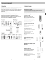 4
4
-
 5
5
-
 6
6
-
 7
7
-
 8
8
-
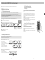 9
9
-
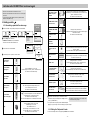 10
10
-
 11
11
-
 12
12
-
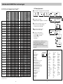 13
13
-
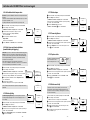 14
14
-
 15
15
-
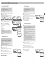 16
16
-
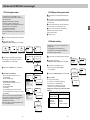 17
17
-
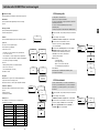 18
18
-
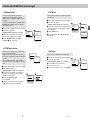 19
19
-
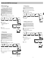 20
20
-
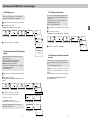 21
21
-
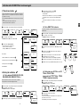 22
22
-
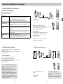 23
23
-
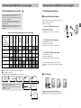 24
24
-
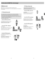 25
25
-
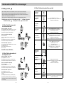 26
26
-
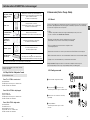 27
27
-
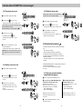 28
28
-
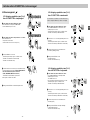 29
29
-
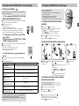 30
30
-
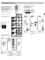 31
31
-
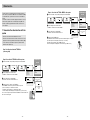 32
32
-
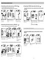 33
33
-
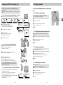 34
34
-
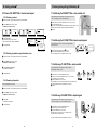 35
35
-
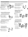 36
36
-
 37
37
-
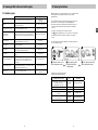 38
38
-
 39
39
-
 40
40
-
 41
41


DELTA DORE CS 8000 TYXAL+ Installation guide
- Category
- Security access control systems
- Type
- Installation guide
- This manual is also suitable for
Ask a question and I''ll find the answer in the document
Finding information in a document is now easier with AI
Related papers
-
DELTA DORE CS 8000 TYXAL+ Installation guide
-
-
-
-
-
DELTA DORE TTGSM TYXAL+ EU Installation guide
-
-
-
-
Other documents
-
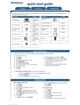 Safe-at-home Security System Quick start guide
-
FAAC 868SLH Owner's manual
-
Evolveo alarmex User manual
-
Hikvision DS-PWA Series User guide
-
Myfox FO3005 Datasheet
-
HKC SW 10270 User manual
-
Enabling Devices 1499 User manual
-
-
Daitem SH402AX Installation guide
-
Denver SHA-150 User manual
