Page is loading ...

1
Chapter 1 Introduction
EC900-FS6
Fanless Embedded System
User’s Manual
A-483-M-2020

2
Chapter 1 Introduction
Copyright
This publication contains information that is protected by copyright. No part of it may be re-
produced in any form or by any means or used to make any transformation/adaptation without
the prior written permission from the copyright holders.
This publication is provided for informational purposes only. The manufacturer makes no
representations or warranties with respect to the contents or use of this manual and specifi-
cally disclaims any express or implied warranties of merchantability or fitness for any particular
purpose. The user will assume the entire risk of the use or the results of the use of this docu-
ment. Further, the manufacturer reserves the right to revise this publication and make changes
to its contents at any time, without obligation to notify any person or entity of such revisions
or changes.
Changes after the publication’s first release will be based on the product’s revision. The website
will always provide the most updated information.
© 2018. All Rights Reserved.
Trademarks
Product names or trademarks appearing in this manual are for identification purpose only and
are the properties of the respective owners.
FCC and DOC Statement on Class A
This equipment has been tested and found to comply with the limits for a Class B digital
device, pursuant to Part 15 of the FCC rules. These limits are designed to provide reason-
able protection against harmful interference when the equipment is operated in a residential
installation. This equipment generates, uses and can radiate radio frequency energy and, if not
installed and used in accordance with the instruction manual, may cause harmful interference
to radio communications. However, there is no guarantee that interference will not occur in a
particular installation. If this equipment does cause harmful interference to radio or television
reception, which can be determined by turning the equipment off and on, the user is encour-
aged to try to correct the interference by one or more of the following measures:
• Reorient or relocate the receiving antenna.
• Increase the separation between the equipment and the receiver.
• Connect the equipment into an outlet on a circuit different from that to which the receiver
is connected.
• Consult the dealer or an experienced radio TV technician for help.
Notice:
1. The changes or modifications not expressly approved by the party responsible for compli-
ance could void the user’s authority to operate the equipment.
2. Shielded interface cables must be used in order to comply with the emission limits.

3
Chapter 1 Introduction
Table of Contents
About this Manual .................................... 4
Warranty ................................................. 4
Static Electricity Precautions ..................... 4
Safety Measures....................................... 4
Safety Precautions ................................... 5
About the Package ................................... 5
Before Using the System .......................... 5
Chapter 1 - Introduction ........................... 6
Overview .................................................................................6
Key Features ...........................................................................6
Specifications ...........................................................................7
Getting to Know the EC900-FS6 ...............................................8
Mechanical Dimensions ............................................................9
Chapter 2 - Getting Started ...................... 10
Chapter 3 - Installing Devices ................... 11
Removing the Chassis Cover ...................................................11
Chapter 4 - Jumper Settings ..................... 13
Boot Mode Select ...................................................................13
Chapter 5 - Ports and Connectors ............. 14
Panel I/O Ports ...................................................................... 14
RJ45 LAN Ports ........................................................................ 15
9~36V DC-in .......................................................................... 15
USB Ports................................................................................ 16
Serial Port ............................................................................... 16
Graphics Interface .................................................................... 17
I/O Connectors ...................................................................... 17
Digital I/O Connector ................................................................ 17
Serial Port ............................................................................... 18
Expansion Slots ....................................................................... 19
I
2
C Connector ......................................................................... 19
Front Panel Connector .............................................................. 20
Battery ................................................................................... 20
Debug Connectors ................................................................... 21
Chapter 6 - Mounting Options .................. 22
Chapter 7 - Supported Software ............... 23

4
Chapter 1 Introduction
About this Manual
An electronic file of this manual can be obtained from the DFI website at www.dfi.com. To
download the user’s manual from our website, please go to Support > Download Center. On
the Download Center page, select your product or type the model name and click "Search" to
nd all technical documents including the user's manual for a specic product.
Warranty
1. Warranty does not cover damages or failures that arised from misuse of the product,
inability to use the product, unauthorized replacement or alteration of components and
product specifications.
2. The warranty is void if the product has been subjected to physical abuse, improper instal-
lation, modification, accidents or unauthorized repair of the product.
3. Unless otherwise instructed in this user’s manual, the user may not, under any circum-
stances, attempt to perform service, adjustments or repairs on the product, whether in or
out of warranty. It must be returned to the purchase point, factory or authorized service
agency for all such work.
4. We will not be liable for any indirect, special, incidental or consequential damages to the
product that has been modified or altered.
Static Electricity Precautions
It is quite easy to inadvertently damage your PC, system board, components or devices even
before installing them in your system unit. Static electrical discharge can damage computer
components without causing any signs of physical damage. You must take extra care in han-
dling them to ensure against electrostatic build-up.
1. To prevent electrostatic build-up, leave the system board in its anti-static bag until you are
ready to install it.
2. Wear an antistatic wrist strap.
3. Do all preparation work on a static-free surface.
4. Hold the device only by its edges. Be careful not to touch any of the components, contacts
or connections.
5. Avoid touching the pins or contacts on all modules and connectors. Hold modules or con
nectors by their ends.
Safety Measures
To avoid damage to the system:
• Use the correct AC input voltage range.
To reduce the risk of electric shock:
• Unplug the power cord before removing the system chassis cover for installation or servic-
ing. After installation or servicing, cover the system chassis before plugging the power cord.
Battery:
• Danger of explosion if battery incorrectly replaced.
• Replace only with the same or equivalent type recommend by the manufacturer.
• Dispose of used batteries according to local ordinance.
Important:
Electrostatic discharge (ESD) can damage your processor, disk drive and other com-
ponents. Perform the upgrade instruction procedures described at an ESD worksta-
tion only. If such a station is not available, you can provide some ESD protection by
wearing an antistatic wrist strap and attaching it to a metal part of the system chas-
sis. If a wrist strap is unavailable, establish and maintain contact with the system
chassis throughout any procedures requiring ESD protection.

5
Chapter 1 Introduction
About the Package
The package contains the following items. If any of these items are missing or damaged,
please contact your dealer or sales representative for assistance.
• One EC900-FS6 system unit
• One Quick Installation Guide
Optional Items
• DIN-rail Mount kit
• Power Cord
The board and accessories in the package may not come similar to the information listed
above. This may differ in accordance to the sales region or models in which it was sold. For
more information about the standard package in your region, please contact your dealer or
sales representative.
Safety Precautions
• Use the correct DC input voltage range.
• Unplug the power cord before removing the system chassis cover for installation or servic-
ing. After installation or servicing, cover the system chassis before plugging the power cord.
• Danger of explosion if battery incorrectly replaced.
• Replace only with the same or equivalent type recommend by the manufacturer.
• Dispose of used batteries according to local ordinance.
• Keep this system away from humidity.
• Place the system on a stable surface. Dropping it or letting it fall may cause damage.
• The openings on the system are for air ventilation to protect the system from overheating.
DO NOT COVER THE OPENINGS.
• Place the power cord in such a way that it will not be stepped on. Do not place anything on
top of the power cord. Use a power cord that has been approved for use with the system
and that it matches the voltage and current marked on the system’s electrical range label.
• If the system will not be used for a long time, disconnect it from the power source to avoid
damage by transient overvoltage.
• If one of the following occurs, consult a service personnel:
- The power cord or plug is damaged.
- Liquid has penetrated the system.
- The system has been exposed to moisture.
- The system is not working properly.
- The system dropped or is damaged.
- The system has obvious signs of breakage.
• The unit uses a three-wire ground cable which is equipped with a third pin to ground the
unit and prevent electric shock. Do not defeat the purpose of this pin. If your outlet does
not support this kind of plug, contact your electrician to replace the outlet.
• Disconnect the system from the DC outlet before cleaning. Use a damp cloth. Do not use
liquid or spray detergents for cleaning.

6
Chapter 1 Introduction
Chapter 1 - Introduction
Chapter 1
Overview
Key Features
Front View
Model Name EC900-FS6
Processor NXP i.MX6 Series Processor
NXP i.MX6 Cortex-A9 Dual Lite, 1.0GHz
LAN Two LAN ports
COM Two serial port:
2-wire RS485
4-wire RS422
Display One HDMI
USB Two USB 2.0 Type A ports
Digital input/output Terminal block for digital I/O with power
Left View

7
Chapter 1 Introduction
Specications
Chapter 1
Vibration • Operating: Random 5~500Hz, IEC68-2-64 (3G)
• Non-Operating: Sine 10~500Hz, IEC68-2-6 (3G)
Shock • Operating: 3G, 11ms
• Non-Operating: 5G, 11ms
Construction
• Sheet Metal
Mounting
• DIN-rail Mount
Dimensions • 145mm x 34mm x 96.4mm (W x H x D)
Weight • TBD
OS Support Yocto 1.8 beta, Kernel 3.14.52
Android 5.1 beta, Kernel 3.14.52
Processor
System
NXP i.MX6 Series Processor
NXP i.MX6 Cortex-A9 Dual Lite, 1.0GHz
Memory • 1GB/2GB SDRAM Memory Down
Single Channel DDR3L 1600MHz
Graphics • Display interface
HDMI: resolution up to 1920x1080 @ 60 Hz
Storage/
Expansion
• Storage
4MB NOR Flash
8GB/16GB eMMC
• Expansion:
1 x Full-size Mini PCIe (PCIe/USB)
1 x microSD
Ethernet • 1 x ATHEROS Ethernet Controller AR8033-AL1B (10/100/1000Mbps)
• 1 x Microchip's USB to Ethernet Controller LAN7500-ABZJ
(10/100/1000Mbps)
I/O Ports and
LED Indicators
• Front Panel
- 2 x RJ-45 LAN ports
- 1 x RS-485 (2-wire terminal block)
- 2 x USB 2.0 (type A)
- 1 x HDMI
- 1 status LED
- 1 reset button
• Side Panel
- 1 x RS-422 (4-wire terminal block)
- 1 x DIO (with power) connector (6-wire terminal block)
Power • 9~36V DC-in
Environment • Temperature
- Operating: -20
o
C ~ 60
o
C
-40
o
C ~ 70
o
C
- Storage: -40 to 85°C
• Relative Humidity
- 10% to 90% RH (non-condensing)

8
Chapter 1 Introduction
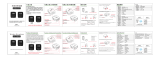
Status LED (blue)
This LED will blink when the system is in the standby mode.
Reset Button
Press to reset the system without disconnecting the system’s power.
USB 2.0 Ports
Connect USB 2.0 and 1.1 devices.
LAN Ports
Connect the system to a local area network.
RS485 Port
Connects RS485 devices.
HDMI Port
Connects the HDMI port of a display device.
Getting to Know the EC900-FS6
Chapter 1
Front View
Rear View
DC-in Connector
DC 9~36V power input via a terminal block connector.
DIO Connector with Power
Provides 4-bit digital input/output with power connectivity (2-pin).
RS422 Port
Connects RS422 devices.
Status LED
(green)
LAN 2 LAN 1
COM (RS485)
USB 2.0
HDMI
Reset
Status LED
Suspend Mode S0 Sleep S4, S5
LED Behavior
On Blinking Off
Digital IO
(4-pin)
RS422 (4-pin)
DC-in
̶ +
Power (1-pin)
Ground (1-pin)

9
Chapter 1 Introduction
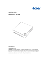
Mechanical Dimensions
Chassis Dimension
Chapter 1
145
34
96.40
Left View
Right View
Front View
Bottom View
Top View

10
Chapter 2 Getting Started
Chapter 2 - Getting Started
Chapter 2
Preparing the System
Before you start using the system, you need the following items:
• AC power cord
• Screwdriver
Installing Devices
The following devices can be installed in the system.
• Mini PCIe card
• micro SD
Configuring the BIOS
To get you started, you may need to change configurations such as the date, time and the
type of hard disk drive.
1. Power on the system.
2. After the memory test, the message “Press DEL to run setup” will appear on the screen.
Press the Delete key to enter the BIOS setup utility.
Installing the Operating System
The device platform is an embedded system with Yocto 1.8 beta or Android 5.1 beta pre-
loaded on the eMMC.

11
Chapter 3 Installing Devices
Chapter 3
1. Make sure the system and all other peripheral devices connected to it have been
powered off.
2. Disconnect all power cords and cables.
3. The 3 mounting screws on the rear and bottom sides of the system are used to secure
the cover to the chassis. Remove these screws and put them in a safe place for later
use.
Chapter 3 - Installing Devices
Removing the Chassis Cover
Please observe the following guidelines and follow the procedure to open the system.
Chassis screw
Opening to SW5
(see Chapter 4 - Jumper Settings)
4. Lift the cover to open the system. The Mini PCIe socket is readily accessible after removing the
bottom cover.
Mini PCIe socket
Micro SD slot
(on the back side)

12
Chapter 3 Installing Devices
Chapter 3
The system board is equipped with one Mini PCIe slot that supports both PCIe and USB signals.
1. Grasp the Mini PCIe card by its edges and align the notch of the PCIe card with the key in
the connector on the system board.
2. Push down on the other end of the Mini PCIe card and use the provided mounting screw to
secure the card on the system board.
Installing a Mini PCIe Card
3. Push down on the other end of the Mini PCIe card and use the provided mounting screw to
secure the card on the system board.
Mounting screw
Antenna holes
Note:
If installing a wireless module, place the antenna cable(s) on top of the Mini PCIe
and route the cables to the side of the chassis to reach the antenna holes.

13
Chapter 4 Jumper Settings
Chapter 4
Front
Panel
COM 3
1
microSD
eMMC
1 5
NXP
i.MX6
Cortex-A9
Boot Mode/Device Select
(SW5)
ON
1 2 3 4 5 6 7 8
5 9
I C
2
1
LVDS LCD Panel
1
14
DDR3L
DDR3L
Chapter 4 - Jumper Settings
Boot Mode Select
SW5
1 2 3 4 5 6 7
8
Boot Device Select SW5
1 2 3 4 5 6 7 8
eMMC On On Off Off On On Off On
SPI xx xx xx On On Off Off On
SD On Off On Off Off On Off On
To select the boot mode and boot device, please use finger switch SW5.
Boot Mode Select SW5
Boot from the fuses 7 Off, 8 Off
Serial downloader 7 On, 8 Off
Boot from the board settings (default) 7 Off, 8 On
Reserved 7 On, 8 On

14
Chapter 5 Ports and Connectors
Chapter 5
Chapter 5 - Ports and Connectors
Panel I/O Ports
The front panel I/O consists of the following ports:
• Status LED (green)
• Reset button
• Two USB 2.0 ports
• Two RJ45 LAN ports
• COM (RS485) port
• HDMI port
HDMI
RS485
LAN 2 LAN 1
Reset
USB 2.0
Status LED
(green)
The left panel I/O port consists of the following ports:
• 4-pole digital input/output with power (2-pole)
• 4-pole COM (RS422) port
• DC-in connector
RS422
DI/DO
DC-IN

15
Chapter 5 Ports and Connectors
Chapter 5
Panel Backlight/SATA Power
5
1
DC-in
USB 1-2
USB 2.0
1
10
9
2
JTAG
Mini
PCIe
Battery
1
1
9
DIODebug
1
4
DDR3L
DDR3L
Debug LED
1
5
2
USB 3
USB 2.0
USB OTG
COM 1
HDMI
LAN 2
LAN 1
RJ45 LAN Ports
Features
• 2 LAN ports built on Atheros Ethernet PHY AR8033-AL1B (10/100/1000Mbps) and Microchip
USB to Ethernet Controller LAN7500-ABZJ (10/100/1000Mbps)
LAN 1: Atheros Ethernet PHY AR8033-AL1B (10/100/1000Mbps)
LAN 2: Microchip USB to Ethernet Controller LAN7500-ABZJ (10/100/1000Mbps)
LAN 1
LAN 2
Panel Backlight/SATA Power
5
1
DC-in
USB 1-2
USB 2.0
1
10
9
2
JTAG
Mini
PCIe
Battery
1
1
9
DIODebug
1
4
DDR3L
DDR3L
Debug LED
1
5
2
USB 3
USB 2.0
USB OTG
COM 1
HDMI
LAN 2
LAN 1
The LAN ports enable the system board to connect to a local area network with a
network hub.
9~36V DC-in
This 2-pin terminal block is considered a low power solution. This connector is wired as an
external DC-in connector and reset button for power control. Please note that using a voltage
more than the recommended range may fail to boot the system or cause damage to the sys-
tem board.
The reset button allows you to reboot the system without powering off the system first.

16
Chapter 5 Ports and Connectors
Chapter 5
The USB 2.0 ports (USB 1-3) and OTG connector are used for USB communication. In addi-
tion, the USB OTG allows the board and the devices connected to it to switch back and forth
between the roles of host and device.
When the system board is in host mode, it acts as a computer and allows USB peripherals to
be connected through the USB OTG port. When the system board is in device mode, it acts as
a peripheral device connecting to a host computer. And in this mode, the system board can
read and write to the onboard eMMC memory from your host computer by using a micro-B
type USB cable.
Pin Pin Name
1
5V
2
Data-
3
Data+
4
GND
5
NC
Panel Backlight/SATA Power
5
1
DC-in
USB 1-2
USB 2.0
1
10
9
2
JTAG
Mini
PCIe
Battery
1
1
9
DIODebug
1
4
DDR3L
DDR3L
Debug LED
1
5
2
USB 3
USB 2.0
USB OTG
COM 1
HDMI
LAN 2
LAN 1
Panel Backlight/SATA Power
5
1
DC-in
USB 1-2
USB 2.0
1
10
9
2
JTAG
Mini
PCIe
Battery
1
1
9
DIODebug
1
4
DDR3L
DDR3L
Debug LED
1
5
2
USB 3
USB 2.0
USB OTG
COM 1
HDMI
LAN 2
LAN 1
USB Ports
USB 2.0
The COM 1 port provides 2-wire RS485 communication with support for auto flow control.
Pin Pin Name Pin Pin Name
1
RS485-
2
RS485+
COM 1
Serial Port
1 2
1
2
5

17
Chapter 5 Ports and Connectors
Chapter 5
Panel Backlight/SATA Power
5
1
DC-in
USB 1-2
USB 2.0
1
10
9
2
JTAG
Mini
PCIe
Battery
1
1
9
DIODebug
1
4
DDR3L
DDR3L
Debug LED
1
5
2
USB 3
USB 2.0
USB OTG
COM 1
HDMI
LAN 2
LAN 1
The HDMI port which carries both digital audio and video signals is used to connect the HDMI
port of an LCD monitor or a digital TV.
The system supports dual and triple display with these ports.
HDMI
Graphics Interface
The display port consists of the following:
• 1 HDMI port
I/O Connectors
Digital I/O Connector
The internal digital I/O connector supports 8-bit digital input/output with power connectivity to
provide monitoring and control function of the devices connected to the DIO port.
Pin Pin Name
1
GPIO0
2
GPIO1
3
GPIO2
4
GPIO3
5
GPIO4
6
GPIO5
7
GPIO6
8
GPIO7
9
3.3V
10
GND
Panel Backlight/SATA Power
5
1
DC-in
USB 1-2
USB 2.0
1
10
9
2
JTAG
Mini
PCIe
Battery
1
1
9
DIODebug
1
4
DDR3L
DDR3L
Debug LED
1
5
2
USB 3
USB 2.0
USB OTG
COM 1
HDMI
LAN 2
LAN 1
1
2
9
10
Digital I/O
External Connector
1 2 3 4 5 6
External DIO Connector
Pin Pin Name
1
DIO0
2
DIO1
3
DIO2
4
DIO3
5
PWR (3.3V)
6
GND (ground)
Internal DIO Connector

18
Chapter 5 Ports and Connectors
Chapter 5
Serial Port
Front
Panel
COM 3
1
microSD
eMMC
1 5
NXP
i.MX6
Cortex-A9
Boot Mode/Device Select
(SW5)
ON
1 2 3 4 5 6 7 8
5 9
I C
2
1
LVDS LCD Panel
1
14
DDR3L
DDR3L
COM 3 can be used for RS232, RS422 or RS485 communication. And the RS485 supports auto
flow control. This internal connector is wired as an RS-422 external port.
The serial port is asynchronous communication ports with 16C550A-compatible UARTs that can
be used with modems, serial printers, remote display terminals, and other serial devices.
COM 3: RS232/422/485
2
1
9
External Connector
1 2 3 4
Pin External RS-422
1
TX_B
2
TX_A
3
RX_A
4
RX_B

19
Chapter 5 Ports and Connectors
Chapter 5
Front
Panel
COM 3
1
microSD
eMMC
1 5
NXP
i.MX6
Cortex-A9
Boot Mode/Device Select
(SW5)
ON
1 2 3 4 5 6 7 8
5 9
I C
2
1
LVDS LCD Panel
1
14
DDR3L
DDR3L
Expansion Slots
Front
Panel
COM 3
1
microSD
eMMC
1 5
NXP
i.MX6
Cortex-A9
Boot Mode/Device Select
(SW5)
ON
1 2 3 4 5 6 7 8
5 9
I C
2
1
LVDS LCD Panel
1
14
DDR3L
DDR3L
Panel Backlight/SATA Power
5
1
DC-in
USB 1-2
USB 2.0
1
10
9
2
JTAG
Mini
PCIe
Battery
1
1
9
DIODebug
1
4
DDR3L
DDR3L
Debug LED
1
5
2
USB 3
USB 2.0
USB OTG
COM 1
HDMI
LAN 2
LAN 1
Mini PCI Express Slot
The full-size Mini PCIe socket supports PCIe x1 signals and is used to install a Mini PCIe card.
microSD Socket (on the back side)
The microSD socket allows you to install a microSD card for the expansion of available storage.
I
2
C Connector
The I
2
C connector is used to monitor or communicate with system components which does not
require high speed communication.
I
2
C
1
2
5
Pin Pin Name
1
3.3V
2
GND
3
I2C_Clock
4
I2C_ALERT-
5
I2C_DATA

20
Chapter 5 Ports and Connectors
Chapter 5
Front
Panel
COM 3
1
microSD
eMMC
1 5
NXP
i.MX6
Cortex-A9
Boot Mode/Device Select
(SW5)
ON
1 2 3 4 5 6 7 8
5 9
I C
2
1
LVDS LCD Panel
1
14
DDR3L
DDR3L
Front Panel Connector
The lithium ion battery powers the real-time clock and CMOS memory. It is an auxiliary source
of power when the main power is shut off.
Safety Measures
• Danger of explosion if battery incorrectly replaced.
• Replace only with the same or equivalent type recommend by the manufacturer.
• Dispose of used batteries according to local ordinance
.
Battery
Connect to the battery connector
Battery
Front
Panel
Status LED
The front panel connector includes a reset button and a power LED.
Pin Pin Name Pin Pin Name
1
NC
2
Power_LED
3
GND
4
NC
5
Reset Button
6
NC
+3.3V
1
GND
2
Battery
Panel Backlight/SATA Power
5
1
DC-in
USB 1-2
USB 2.0
1
10
9
2
JTAG
Mini
PCIe
Battery
1
1
9
DIODebug
1
4
DDR3L
DDR3L
Debug LED
1
5
2
USB 3
USB 2.0
USB OTG
COM 1
HDMI
LAN 2
LAN 1
2
1
5
6
/