Page is loading ...

Agri-Fab ®
OWNERS
MANUAL
Model No.
45-0350 (ATV)
45-0351 (FARM)
CAUTION
Read Rules for
Safe Operation
and Instructions
Carefully
(45-0350 SHOWN)
TANDEM AXLE CART
• Safety
• Assembly
• Operation
• Maintenance
• Parts
PRINTED IN USA
SpeedEPart the_as_es_wa_topurchasepa_t_
www.speedepart.com
FORM NO. 48902 (REV. 1/04)

SAFETY RULES
Remember, any power equipment can cause injury if operated improperly or if the user does not understand how
to operate the equipment. Exercise caution at all times when using power equipment.
LOOK FOR THIS SYMBOL TO POINT OUT
IMPORTANT SAFETY PRECAUTIONS. IT
MEANS-- ATTENTION! BECOME ALERT!
YOUR SAFETY IS INVOLVED.
CAUTION: VEHICLE BRAKING AND
,_ STABILITY MAY BE AFFECTED WITH
THE ADDITION OF AN ACCESSORY
OR AN ATTACHMENT. BE AWARE OF
CHANGING CONDITIONS ON SLOPES.
1. Read this owners manual before attempting to assemble or operate the cart.
2. Read the vehicle owners manual and know how to operate your vehicle, before using the cart attachment.
3. Do not at any time carry passengers in this cart. It has not been designed to carry passengers.
4. Never allow children to operate the vehicle or the cart attachment.
5. Do not allow adults to operate the vehicle or cart attachment without proper instructions.
6. Always begin with the transmission in first (low) and gradually increase speed as conditions permit.
7. Tow the cart at reduced speed over rough terrain and hillsides or near creeks and ditches to prevent tipping
over and loss of control. Do not drive too close to a creek or ditch.
8. Vehicle braking and stability will be affected with the attachment of this cart. Do not fill cart to maximum weight
capacity without checking the capability of the towing vehicle to safely pull and stop with the cart attached.
9. Before operating vehicle on any grade (hill) refer to the safety rules in the vehicle owner's manual concerning
safe operation on slopes. Refer also to the slope guide on page 9 of this manual. Stay off steep slopes!
10. Do not tow this cart on highways or on public thoroughfares.
11. Follow maintenance and lubrication instructions as outlined in this manual.
CARTON CONTENTS
1. Tailgate Guides (2)
2. Corner Caps (2)
3. Latch Lock Lever
4. Hitch Bracket
5. Latch Stand Bracket
6. Wheel Support
7. Tailgate
8. Front Panel
9. Tailgate Reinforcement Bracket
10. Draw Bar Tongue
11. Axle
12. Cart Body (2)
13. Wheels (4)
14. Walking Beam (2)
Model 45-0350 only
15. Front Rail
16. Side Rail (2)
17. Rail Brace (7)
"- _% _.
...._._
CARTON CONTENTS

B
J
SHOWN FULL SIZE
P
O
Q
jS
T
\J
_J
jU
V
HARDWARE PACK
NOT SHOWN FULL SIZE
_X
Ref.
A
B
C
D
E
F
G
H
I
J
K
L
M
Description
Hex Bolt, 5/16-18 x 4"
Curved Head Bolt
Hex Bolt, 3/8" x 1"
Truss Hd. Bolt, 5/16" x 3/4"
Hex Bolt, 1/4" x 3/4"
Hex Bolt, 1/4" x 1/2"
45-0350
1
8
1
12
13
21
45-0351 Ref.
1 N
-- O
1 P
12 Q
-- R
25 S
Description
Lock Washer, 3/8"
Flat Washer, 1/4"
Flat Washer, 5/16"
1" Thin Washer, (8 pcs. extra)
1" Thick Washer
Spring
45-0350
1
13
2
2O
4
1
SEMS Nut, 1/4"
SEMS Nut, 5/16"
Hex Nut, 5/16"
Hex Nut, 3/8"
Nylock Nut, 1/4"
Nylock Nut, 5/16"
Lock Washer, 5/16"
21
14
8
1
13
1
8
25
14
1
1
T
U
V
W
X
Y
Z
AA
Cotter Pin, 1/8" x 1-1/2" Lg.
Hair Cotter Pin 1/8"
Spacer
Hitch Pin
Vinyl Edging
Vinyl Cap
Spring Puller Tool
Hub Cap
6
1
4
1
2
2
1
6
45-0351
1
2
2O
1
6
1
4
1
2
1
6

ASSEMBLY INSTRUCTIONS
TOOLS REQUIRED FOR ASSEMBLY
(1) Screwdriver
(1) Pliers
(2) 7/1 6" Wrenches
(2) 1/2" Wrench
(2) 9/1 6" Wrenches
(1) Grease Gun with general purpose grease
1. Remove the hardware pack and all loose parts
from the carton. Be sure the carton is empty
before discarding.
2. Lay out all parts as shown. Extra pieces of some
items may be included in hardware pack.
CAUTION
Do not leave the cart unattended in the upright
position. A falling cart can cause personal injury!
Pay close attention to the stability of the cart while
it remains in an upright position. For best stability,
assemble on a smooth, level surface.
NOTE: To prevent scratching paint, cover work surface
with a mat or cardboard.
3. Position cart body halves upright on a smooth
level surface such as a garage floor or a paved
driveway. See figure 1.
4. Assemble halves together using five 1/4" x 1/2"
hex bolts and 1/4" SEMS nuts as shown in figure
1. Do not tighten yet.
i
114" x 112" HEX BOLT
114" SEMS NUT
5. Position the tailgate reinforcement bracket on
outside of cart as shown in figure 3. Assemble to
the bottom of the cart body using four 5/16" x 3/4"
truss head bolts and 5/16" SEMS nuts. Do not
tighten yet. See figure 2.
6. Position the tailgate guides on the inside of the
cart bodies with guide channels to the front. As-
semble using four 1/4" x 1/2" hex bolts and 1/4"
SEMS nuts. Do not tighten yet. See figure 2.
7. (45-0351 only) Fasten the ends of the tailgate
reinforcement bracket to the top flange of the cart
using two 1/4" x 1/2" hex nuts and 1/4" SEMS
washers. See figure 2.
8. At this time, with the cart body halves pulled
together, tighten the truss head bolts assembled
in step 5 and then tighten the hex bolts as-
sembled in steps 6 and 7. Do not tighten the bolts
that were assembled in step 4.
TAILGATE GUIDE
1/4" SEMS NUT
I
i
5116"SEMS NUT
114"x 112"
1/4" x 1/2" HEX BOLT
HEX BOLT (45-0351 only)
\
5116" x 314" \
\
TRUSS HEAD
/ BOLT ._
TAILGATE 114" SEMS NUT
REINFORCEMENT (45-0351 only)
BRACKET
FIGURE 2
9. Carefully turn the cart over so that the tailgate rein-
forcement bracket is on the bottom. See figure 3.
}
8
@
0
@
TAILGATE
REINFORCEMENT
BRACKET
/
FIGURE 1 FIGURE 3
4

10.Assemblethefrontpanelovertheendofthecart
usingsix1/4"x 1/2"hexboltsand1/4"SEMSnuts
as shownin figure 4. Leavetwo holes in the
bottomofthepanelemptyasshown.Pullthecart
bodyhalvestogetherandtighten theboltsinthe
bottomofthefrontpanel,thentighten theboltsin
thesides.Seefigure4.
11.Tighten the boltsassembledin step 4to fasten
thebottomof thecarttogether.
LEAVE HOLES OPEN FOR
LATCH STAND BRACKET
1/4" x 1/2"
HEX BOLTS
1/4" SEMS NUT
x
&`
/
1/4" SEMS NUT
14. Assemble the wheel support to the cart using eight
5/16" x 3/4" truss head bolts and 5/16" SEMS nuts
as shown in figure 6. Heads of bolts go on the
inside of the cart. Tighten.
5/16" x 3/4"
TRUSS HEAD BOLT
WHEEL
SUPPORT
\
5/16"
SEMS
NUT
FIGURE 6
FIGURE 4
12. Assemble the latch stand bracket to the cart so that
the aligning tab is at the bottom of the bracket. Use
four 1/4" x 1/2" hex bolts and 1/4" SEMS nuts.
Tighten. See figure 5.
13. Assemble a corner cap to each front corner using
one ortwo 1/4" x 1/2" hex bolts and 1/4" SEMS nuts
per cap. Leave out the rear bolt if the cart has top
rails (model 45-0350 only). TIGHTEN. See figure 5.
LATCH STAND BRACKET _ --\
(Aligning tab at bottom)
Leaveout on
Model 45-0350
/\, i! ]
FIGURE 5
15. Lower the cart to rest upside down on its top flange
with the wheel support facing up. See figure 7.
16. Lay the drawbar tongue (open side facing up) onto
the Wheel Support and the Latch Stand Bracket.
Slide the axle through the wheel support and the
tongue. See figure 7.
AXLE
DRAW BAR
TONGUE
_,i LATCH STAND
',i BRACKET
FIGURE 7

17. Hold the latch lock lever as shown in figure 8 and
place it down through the slot in the draw bar tongue.
Assemble the 5/16" x 4" hex bolt through the tongue,
the lever and two 5/16" SEMS nuts (one on each side
of the lever). Assemble the 5/1 6" nylock nut onto the
end of the bolt and tighten so that the bolt can still
rotate freely. Tighten the two 5/16" SEMS nuts
against the sides of the latch lock lever so that the
lever is centered in the slot. See figure 8.
5/16" SEMS NUTS
LATCH
_, LOCK
LEVER
5/16"
NYLOCK
_- NUT
FIGURE 8
19.
20.
Assemble the end of the hitch bracket (two holes)
up through the slot at the front of the drawbar
tongue. Fasten it to the tongue using the 3/8"x1"
hex bolt, 3/8" lock washer and 3/8" hex nut.
Tighten. See figure 10.
Assemble the hitch pin through the hitch bracket
and the tongue and secure it with the 1/8" hair
cotter pin. See figure 10.
318"HEX
NUT
.................... 318"LOCK \
..........WASHER \
1/8" HAIR
COTTER
PIN
/
I
318" x 1"
HEX BOLT
=
HITCH
BRACKET
=-
HITCH PIN
/
FIGURE 10
18. Hook the short end of the spring into the hole in the
latch lock lever. Use the spring puller tool to hook the
long end of the spring into the square hole in the
tongue. The spring puller tool can be stored when
finished. See figure 9.
,/
!----SPRING PULLER TOOL
LONG END
OF SPRING
LATCH LOCK LEVER
21. Assemble a 1" thin washer, a walking beam and
another 1" thin washer onto the pivot axle. Insert a
cotter pin into the axle and spread the ends. Press a
hub cap onto the flat washer. Repeat on the other end
of the pivot axle. See figure 11.
NOTE: Eight extra 1" flat washers are provided to take
up end play if necessary.
1" THIN WASHER
1/8" x 1-1/2"
\ COTTER PIN
HUB CAP
WALKING BEAM
FIGURE 9 FIGURE 11
6

22.Assemblea 1" thin washer,a spacer,a 1" thick
washer(model45-0350only),awheelwiththevalve
stemfacingout,andanother1"thinwasherontoa
wheelaxle.Inserta cotterpin into the axle and
spreadtheends.Repeatfortheotherthreewheels.
Seefigure12.
NOTE:Eightextra1"thinwashersareprovidedtotake
upendplayif necessary.
23.Pressahubcapontotheflatwasheroneachofthe
fourwheels.Seefigure12.
24.Checktirepressure(max.psiprintedontire).
25.Pumpthewheelhubsfullofgeneralpurposegrease.
1"THIN
SPACER
WASHER
HUB CAP
\
1" THICK _-_
WASHER
(45-0350 ONLY)
1/8" x 1-1/2" 1"THIN WHEEL
COTTER PIN WASHER (45-0350 SHOWN)
FIGURE 12
IMPORTANT: Make sure the drawbar tongue is locked
to the latch stand bracket by the latch lock lever.
26. Turn cart over onto its wheels.
27. (Model 45-0350 only) Press the protective edging
strips onto the ends of the tailgate. See figure 13.
28. Slide the tailgate down into the tailgate guides so that
the holes in the bottom of the tailgate fit over the
screws in the bottom of the cart bed. See figure 13.
PROTECTIVE EDGING (45-0350
FIGURE 13
ASSEMBLING RAILS - MODEL 45-0350 ONLY
29. Assemble seven rail braces to the top flange on the
sides and the front of the cart bed. Use thirteen 1/4"
x 3/4" hex bolts, 1/4" flat washers and 1/4" nylock
nuts. Do not tighten yet. See figure 14.
I/4"NYLOCK NUT
FIGURE 14
5/16" FLAT
WASHER
30. Insert the ends of the side rails into the front rail so
that the holes align. See figure 15.
31. Assemble the rails to the side rail braces using eight
curved head bolts, 5/16" lock washers and 5/16" hex
nuts. Tighten all loose nuts and bolts. See figure 15.
32. Assemble the rails to the front rail braces using two
curved head bolts, 5/16" lock washers, 5/16" flat
washers and 5/16" hex nuts. Tighten all loose nuts
and bolts. See figure 15.
33. Assemble two vinyl caps onto the ends of the rails.
See figure 15.
CURVED
HEAD
BOLT
VINYL
CAP
FIGURE 15
5/16" LOCK
WASHER
5/16" HEX NUT

OPERATION MAINTENANCE
CAUTION: Vehicle braking and stabil-
ity may be affected with the addition of
an accessory or an attachment. Be aware
of changing conditions on slopes.
1. Refer to the vehicle operator's manual for instruc-
tions on safe operation on slopes.
2. Always operate at reduced speed on slopes.
3. Do not operate an ATV towing the cart on a slope
greater than 15 degrees.
4. Do not operate a tractor towing the cart on a slope
greater than 10 degrees. Use the slope guide on
page 9 of this manual.
NOTE
DO NOT EXCEED WEIGHT CAPACITY OF CART
(See the specifications on this page for each model)
One cubic foot of dirt weighs approximately 150 Ibs.
5. For best handling and traction, distribute the weight
of the load evenly in the cart.
6. Always test to make sure your vehicle has adequate
towing and braking capabilities when towing a load in
your cart. Use extra caution when operating on slopes.
7. Operate at reduced speed when towing a load.
8. The 45-0350 cart should not exceed 20 m.p.h., or
your vehicle's maximum safe towing speed, which-
ever is less. Refer to your vehicle operator's manual.
9. The 45-0351 cart should not exceed 10 m.p.h., or
your vehicle's maximum safe towing speed, which-
ever is less. Refer to your vehicle operator's manual.
1. Check for loose fasteners before each use.
2. At the beginning of each season, lubricate the
latch, the latch pivot bolt, and the bearings in the
walking beams with a light machine oil.
3. Grease the wheel bearings periodically. Use gen-
eral purpose grease.
4. Keep tires filled to the pressure recommended on
the tires.
CART MODEL SPECIFICATIONS
MODEL 45-0350 ATV CART
Tires: 18.00" x 9.5" Knobby Tread
Axle: 1.0" Dia. High Carbon Steel
Capacity: Up to 1000 Lbs. Max.
Approx. Sh. Wt. 208 Lbs.
MODELS 45-0351 FARM CART
Tires: 16.00" x 6.5" Turf Tread
Axle: 1.0" Dia. High Carbon Steel
Capacity: Up to 1000 Lbs. Max.
Approx. Sh. Wt. 195 Lbs.
_. CAUTION: Do not exceed the towing
capacity of the vehicle. Follow any weight
limitations listed in the vehicle operator's
manual.
10. To dump material from the cart, remove the tailgate
by lifting it straight up and out from between the
guides. Release the spring latch on the tongue by
pulling the latch lock lever forward, away from the
cart. The cart bed will then tilt backwards to empty its
contents. After emptying, pull the front of the bed
down toward the cart tongue until the latch snaps into
place. Replace the tailgate if desired.
CAUTION: To avoid possible injury,
before releasing the latch be sure that
no one is near the cart.

o_
UJ _._=_
_
•_ 0
_ "-
UJ sF_
0
.'2_0
--_ .,-.' CAUTION: DO NOT OPERATE YOUR TRACTOR AND CART ON
O _ A SLOPE IN EXCESS OF 10 DEGREES. BE SURE OF YOUR
u) u)
._ -_ TRACTOR'S TOWING AND BRAKING CAPABILITIES BEFORE
.,., =.. OPERATING ON A SLOPE. AVOID ANY SUDDEN TURNS OR
¢ ,,.. MANEUVERS WHILE ON A SLOPE.
_n-

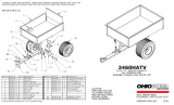
REPAIR PARTS FOR CART MODEL NO'S. 45-0350, 45-0351
MODEL NO. 45-0350 ONLY
34
44
/
/
43
/
/
20
19
/
4 I
17
17
/
12
13
45
16 \
\\,
'14 \15
15
21
27
B
10
25
,7
//
26 .....v
19
29
22
\
w
23" _
24 _ ;
10
9
18

REPAIR PARTS FOR CART MODEL NO'S. 45-0350, 45-0351
REF. PART
NO. NO.
1 25112
2 23502
3 62458
4 23548
5 23492
6 25106
7 24497
8 24498
9 23014
10 25114
11 25107
12 23484
13 43594
48906
14 43093
15 43601
16 43014
17 43175
18 43343
19 46978
20 43814
21 46980
22 43001
23 43003
24 43015
25 47408
26 47622
27 47407
28 47810
29 48948
30 64723
31 44488
32 46289
44678
33 25111
34 44481
35 44947
36 43086
37 43083
38 43012
39 43088
40 47189
41 1540-58
42 48949
43 48951
44 48950
45 44488
46 43081
48902
DESCRIPTION 45-0350 45-0351
Cart Body
Tailgate
Tailgate Reinforcement Bracket
Tailgate Guide
Front Panel
Wheel Support
Latch Stand Bracket
Latch Lock Lever
Hitch Bracket
Draw Bar Tongue
Axle, 1" Dia.
Front Corner Cap
Wheel, 16/6.5" x 8.00 (45-0351)
Wheel, 18/9.5" x 8.00 (45-0350)
Cotter Pin, 1/8" Dia. x 1-1/2" *
Washer, Flat 1" (Thin)
Hub Cap
Hex Bolt, 1/4-20 x 1/2" *
Hair Cotter Pin, 1/8 (#4) *
Hex Nut, 1/4-20 (SEMS)
2
1
1
2
1
1
1
1
1
1
1
2
4
6
20
6
21
1
21
Truss Hd. Bolt, 5/16-18 x 3/4" Lg. *
Hex Nut, 5/16-18 (SEMS)
Hex Bolt, 3/8-16 x 1" Lg. *
Lock Washer, 3/8" *
Hex nut, 3/8-1 6 *
Extension Spring
Spring Puller Tool
Hex Bolt, 5/16-18 x 4" *
Nylock Nut, 5/16-18 *
Hitch Pin
Walking Beam (Includes #44488)
Bearing
Spacer (45-0350)
Spacer (45-0351)
Rail Brace
Vinyl Cap
Curved Hd. Bolt, 5/1 6-18 x 1-5/8"
Lock Washer, 5/16"
Hex Nut, 5/16"
Hex Bolt, 1/4-20 x 3/4"
Flat Washer, 1/4"
Nylock Nut, 1/4"
Washer, 1.03" x 1.38" x .120" (Thick)
Protective Edging Strip
Front Rail
Side Rail
Wheel Bearing (#43594 Wheel)
Flat Washer, 5/16"
Owner's Manual
12
14
1
1
1
1
1
1
1
1
2
4
4
7
2
8
8
8
13
13
13
4
2
1
2
2
1
2
1
1
2
1
1
1
1
1
1
1
2
4
6
20
6
25
1
25
12
14
1
1
1
1
1
1
1
1
2
4
4
7
2
8
* Purchase Common Hardware Locally
SpeedEPart.he as.es..o.urch s p r.swww.speedepart.com
11

$#eedEPmrt_ _ _ to_ _ www.speedepart.com
REPAIR PARTS
Agri-Fab, Inc.
303 West Raymond
Sullivan, IL. 61951
217-728-8388
www.agri-fab.com
/