Electrolux EWGD65HTS0 Installation guide
- Category
- Electric laundry dryers
- Type
- Installation guide

|nsta||ation |nstructions
Electro[u× Front-Load Gas _ Electric DD'er
|nstrucciones de |nsta|acion
Secadora e[_ctfica y a gas de carga fro_3tal Electro[u×
Instructions d'installation
%cheuse _ gaz et _ l'_[ectficit_ _ chargeme_3t fro_3tal Electro[u×

Finding Information
Please read and save this guide
Thank you for choosing Electrolux, the new premium brand in home appliances. These Installation
Instructions are part of our commitment to customer satisfaction and product quality throughout the life
of your new appliance.
We view your purchase as the beginning of a relationship. To ensure our ability to continue serving you,
please use this page to record important product information.
Keep a record for quick reference
Purchase date
Electrolux model number
Electrolux serial number
For toll-free telephone support in the U.S. and Canada: 1-877-4ELECTROLUX {1-877-435-3287)
For online support and product information visit http://www.electroluxappliances.com
Table of contents
Finding information ......................................................... 2
SAFETY .......................................................................... 3
• Pre-installation requirements ...................................... 3
Installation requirements ............................................. 4-9
Electrical system requirements ................................... 4
Gas supply requirements ............................................ 5
Exhaust system requirements ................................. 5-7
Mobile home installation ............................................. 7
Clearance requirements .............................................. 8
installed dimensions ................................................... 9
Installation instructions ........................................... 10-18
Electrical installation ................................................. 10
Grounding requirements - Electric dryer (USA) ........ 10
Grounding requirements - Electric dryer (Canada)... 11
Grounding requirements - Gas dryer ........................ 11
Electrical connection - Electric dryer (3-wire cord)... 12
Electrical connection - Electric dryer (4-wire cord)... 13
Gas connection ........................................................ 14
Water connection (Steam Model only) ................. 15-16
General installation ................................................... 17
Performing installation cycle .................................... 18
Reversing door ........................................................ 19-24
Options ......................................................................... 25
Accessories .............................................................. 25
Replacement parts ................................................... 25
Notes ............................................................................ 26
©2008 Electrolux Major Appliances All rights reserved.

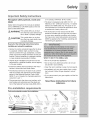
Safety
Important Safety Instructions
Recognize safety symbols, words and
labels
Safety items throughout this manual are labeled
with a WARNING or CAUTION based on the risk
type as described below:
/_X WARNmNG This symbol alerts you to situa-
tions that may cause serious body
harm, death or property damage.
/_ CAUTmON This symbol alerts you to situa-
tions that may cause bodily injury
or property damage.
or in Canada, CAN/ACG B149.1-2000.
The dryer is designed under ANSI Z 21.5.1 or
ANSI/UL 2158- CAN/CSA C22.2 No. 112 (latest
editions) for HOME USE only. This dryer is not
recommended for commercial applications such
as restaurants, beauty salons, etc.
The instructions in this manual and all other
literature included with this dryer are not meant
to cover every possible condition and situation
that may occur. Good safe practice and caution
MUST be applied when installing, operating and
maintaining any appliance.
Read all of the following instructions before
installing and using this appliance:
• Destroy the carton and plastic bags after the dryer
is unpacked. Children might use them for play.
Cartons covered with rugs, bedspreads, or plastic
sheets can become airtight chambers causing suf-
focation. Place all materials in a garbage container
or make materials inaccessible to children.
• Clothes dryer installation and service must be
performed by a qualified installer, service agency
or the gas supplier.
• Install the clothes dryer according to the manu-
facturer's instructions and local codes.
• The electrical service to the dryer must conform
with local codes and ordinances and the latest
edition of the National Electrical Code, ANSI/
NFPA 70, or in Canada, the Canadian electrical
code C22.1 part 1.
• The gas service to the dryer must conform with
local codes and ordinances and the latest edi-
tion of the National Fuel Gas Code ANSI Z223.1,
WHAT TO DO IF YOU SMELL GAS:
• Do not try to light any appliance.
• Do not touch any electrical switch; do not use
any phone in your building.
• Clear the room, building or area of all occupants.
• Immediately call your gas supplier from a neigh-
bor's phone. Follow the gas supplier's instruc-
tions.
If you cannot reach your gas supplier, call the fire
department.
Save these instructions for future
reference.
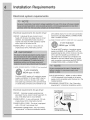
PreoinstaHation requirements
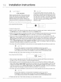
Tools and materials needed for installation:
or
Adjustable Phillips, straight, & Adjustable
pliers square bit screwdrivers wrench
Universal wrench Pipe wrench LP-resistant Carpenter's level
supplied with for gas thread tape
matching washer supply (for natural gas
or LP supply)
1//, NPT union flare
3-wire or 4-wire 4 in. gas line adapters (x2) and
240 volt cord kit (10.2 cm) shutoff valve flexible gas supply line
(electric dryer) clamp (gas dryer) (gas dryer)
External
vent hood
4 inch, rigid metal or Metal foil tape
semi-rigid metal exhaust duct work (not duct tape)

installation Requirements
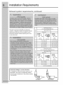
Electrical system requirements
Electrical requirements for electric d_jer:
CIRCUIT - individual 30 amp. branch circuit
fused with 30 amp. time delay fuses or circuit
breakers. Use separately fused circuits for
washer and dryer. DO NOT operate a washer
and a dryer on the same circuit.
POWER SUPPLY - 3-wire or 4-wire, 240 volt,
single phase, 60 Hz, Alternating Current.
3-WIRE POWER SUPPLY CORD KIT (not supplied)
3-wire receptacle
(NEMA type 10-30R)
The dryer MUST employ a 3-conductor power
supply cord NEMA 10-30 type SRDT rated at
240 volt AC minimum, 30 amp, with 3 open
end spade lug connectors with upturned ends
or closed loop connectors and marked for use
with clothes dryers. For 3-wire cord connection
instructions see ELECTRICAL CONNECTIONS
FOR A 3-WIRE SYSTEM.
4-WIRE POWER SUPPLY CORD KIT (not supplied)
4-wire receptacle
(NEMA type 14-30R)
The dryer MUST employ a 4-conductor power
supply cord NEMA 14-30 type SRDT or ST (as
required) rated at 240 volt AC minimum, 30 amp,
with 4 open end spade lug connectors with
upturned ends or closed loop connectors and
marked for use with clothes dryers. For 4-wire
cord connection instructions see ELECTRICAL
CONNECTIONS FOR A 4-WIRE SYSTEM.
OUTLET RECEPTACLE - NEMA 10-30R or NEMA
14-30R receptacle to be located so the power
supply cord is accessible when the dryer is in the
installed position.
GROUNDING CONNECTION - See "Grounding
requirements" in Electrical installation section.
Electrical requirements for gas d_jer:
CIRCUIT - individual, properly polarized and
grounded 15 amp. branch circuit fused with 15
amp. time delay fuse or circuit breaker.
POWER SUPPLY - 2-wire, with ground, 120 volt,
single phase, 60 Hz, Alternating Current.
POWER SUPPLY CORD - The dryer is equipped
with a 120 volt 3-wire power cord.
GROUNDING CONNECTION - See "Grounding
requirements" in Electrical installation section.
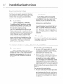
Grounding type
wall receptacle
Do not, under -'_
any circumstances,
cut, remove,
or bypass the
grounding prong.,
Powercord with
3-prong grounded plug

Installation Requirements
Gas supply requirements
1. Installation MUST conform with local codes, or
in the absence of local codes, with the National
Fuel Gas Code, ANSI Z223.1 (latest edition).
2. The gas supply line should be 1/2 inch (1.27
cm) pipe.
3. If codes allow, flexible metal tubing may be
used to connect your dryer to the gas supply
line. The tubing MUST be constructed of
stainless steel or plastic-coated brass.
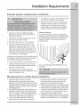
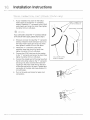
Exhaust system requirements
.
5.
The gas supply line MUST have an individual
shutoff valve.
A 1/8 inch (0.32 cm) N.RT. plugged tapping,
accessible for test gauge connection, MUST
be installed immediately upstream of the gas
supply connection to the dryer.
6. The dryer MUST be disconnected from the
gas supply piping system during any pressure
testing of the gas supply piping system at test
pressures in excess of 1/2 psig (3.45 kPa).
7. The dryer MUST be isolated from the gas supply
piping system during any pressure testing of the
gas supply piping system at test pressures equal
to or less than 1/2 psig (3.45 kPa).
8. Connections for the gas supply must comply
with the Standard for Connectors for Gas
Appliances, ANSI Z21.24.
Use only 4 inch (10.2 cm) diameter (minimum) rigid
or flexible metal duct and approved vent hood
which has a swing-out damper(s) that open when
the dryer is in operation. When the dryer stops,
the dampers automatically close to prevent drafts
and the entrance of insects and rodents. To avoid
restricting the outlet, maintain a minimum of 12
inches (30.5 cm) clearance between the vent hood
and the ground or any other obstruction.
The following are specific requirements
for proper and safe operation of your
dryer.
Correct Incorrect
If your present system _smade up of plastic
duct or metal foil duct, replace it with a rigid or
semi-rigid metal duct. In Canada and the United
States if metal (foil type) duct is installed, it must
be of a specific type identified by the appliance
manufacturer as suitable for use with clothes
dryers and in the United States must also comply
with the Outline for Clothes Dryer Transition Duct,
UL standard 2158A. Also, ensure the present duct
is free of any lint prior to installing dryer duct.

installation Requirements
Exhaust system requirements, continued
The dryer must be connected to an exhaust
outdoors. Regularly inspect the outdoor exhaust
opening and remove any accumulation of lint
around the outdoor exhaust opening and in the
surrounding area.
Z
o
E*
0
1
2
3
4
Z
o
E*
0
1
2
3
MAXIMUM LENGTH
of 4" (10.2cm) Rigid Metal Duct
VENT HOOD TYPE
(Preferred)
4"
(10.2cm) Iouvered
125 ft. (38.10m)
115 ft. (35.05m)
105 ft. (32.00m)
95 ft. (28.96m)
85 ft. (25.91 m)
2.5"
(6.35cm)
110 ft. (33.53m)
100 ft. (30.48m)
90 ft. (27.43m)
80 ft. (24.38m)
70 ft. (21.34m)
MAXIMUM LENGTH
of 4" (10.2cm)Semi-Rigid Metal Duct
VENT HOOD TYPE
(Preferred)
4"
(10.2cm) Iouvered
60 ft. (18.29m)
50 ft. (15.24m)
40 ft. (12.19m)
NOT RECOMMENDED
2.5"
(6.35cm)
45 ft. (13.72m)
35 ft. (10.67m)
25 ft. (7.62m)
Install male fittings in correct direction:
In installations where the exhaust system is not
described in the charts, the following method
must be used to determine if the exhaust system
is acceptable:
CORRECT INCORRECT

Installation Requirements
Exhaust system requirements, continued
.
.
3.
4.
Connect an inclined or digital manometer
between the dryer and the point the exhaust
connects to the dryer.
Set the dryer timer and temperature to air fluff
(cool down) and start the dryer.
Read the measurement on the manometer.
The system back pressure MUST NOT be
higher than 1.0 inch of water column. If the
system back pressure is less than 1.0 inch of
water column, the system is acceptable. If the
manometer reading is higher than 1.0 inch of
water column, the system is too restrictive and
the installation is unacceptable.
Although vertical orientation of the exhaust system
is acceptable, certain extenuating circumstances
could affect the performance of the dryer:
• Only the rigid metal duct work should be used.
Venting vertically through a roof may expose
the exhaust system to down drafts causing an
increase in vent restriction.
Running the exhaust system through an
uninsulated area may cause condensation and
faster accumulation of lint.
Compression or crimping of the exhaust system
will cause an increase in vent restriction.
The exhaust system should be inspected and
cleaned a minimum of every 18 months with
normal usage. The more the dryer is used,
the more often you should check the exhaust
system and vent hood for proper operation.
Exhaust direction
Directional exhausting can be accomplished by
installing a quick-turn 90° dryer vent elbow directly
to exhaust outlet of dryer. Dryer vent elbows are
available through your local parts distributor or
hardware store.
See also CLEARANCE REQUIREMENTS on the
next page.
Manufactured or mobile home installation
1. Installation MUST conform to current
Manufactured Home Construction & Safety
Standard, Title 24 CFR, Part 32-80 (formerly the
Federal Standard for Mobile Home Construction
and Safety, Title 24, HUD Part 280) or Standard
CAN/CSAZ240 MH.
2. Dryer MUST be exhausted outside (outdoors, not
beneath the mobile home) using metal ducting
that will not support combustion. Metal ducting
must be 4 inches (10.16 cm) in diameter with no
obstructions. Rigid metal duct is preferred.
3. If dryer is exhausted through the floor and
area beneath the mobile home is enclosed,
the exhaust system MUST terminate outside
the enclosure with the termination securely
fastened to the mobile home structure.
4. Refer to previous sections in this guide for other
important exhaust venting system requirements.
5. When installing a gas dryer into a mobile home,
a provision must be made for outside make up
air. This provision is to be not less than twice
the area of the dryer exhaust outlet.
6. Installer MUST anchor this (1) dryer or (2) dryer
mounted on pedestal to the floor with approved
Mobile Home Installation Kit - P/N 137067200.

installation Requirements
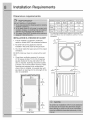
Cmearance requirements
iNSTALLATiON iN A RECESS OR CLOSET
1. A dryer installed in a bedroom, bathroom,
recess or closet, MUST be exhausted outdoors.
2. No other fuel burning appliance shall be
installed in the same closet as the gas dryer.
3. Your dryer needs the space around it for proper
ventilation.
DO NOT install your dryer in a closet with a solid
door.
.
Closet door ventilation required: A minimum
of 120 square inches (774.2 cm 2)of opening,
equally divided at the top and bottom of the
door, is required. Openings should be located
3 inches (7.6 cm) from bottom and top of door.
Openings are required to be unobstructed
when a door is installed. A Iouvered door with
equivalent air openings for the full length of the
door is acceptable.
60 sq. in.
(387.1cm 2}
f
60 sq. in.
(387.1cm 2)
MINIMUM INSTALLATION CLEARANCES -Inches (cm)
SIDES REAR TOP FRONT
Alcove 0" (0 cm) 0" (0 cm)* 0" (0 cm) n/a
Under-
0" (0 cm) 0" (0 cm)* 0" (0 cm) n/a
Counter
Closet 0" (0 cm) 0" (0 cm)* 0" (0 cm) 1" (2.54 cm)
For other than straight back venting, a quick-turn 90°
dryer vent elbow must be installed to achieve 0" (0 cm)
r
o" t
(Ocm)

Installation Requirements
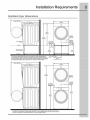
Installed dryer dimensions
50.6" (128.5cm)*
to clear open door
freestand dryer
on floor
optional pedestal
floor line
31.59" (8Ocm)*
to front of closed door
53.00"
(134.5cm)
38.00"
(96.5cm)
* To obtain these minimal depth dimensions, dryer must either be vented straight back or
with a quick-turn 90 ° elbow. Connection of water inlet hose on Steam Models adds 3/4 in.
(2 cm) to installation depth. Upward venting of exhaust on pedestal-mounted or freestandin 9
dryer adds approximately 4 in. (10.2 cm) to installation depth. Downward venting of exhaust
on pedestal-mounted dryer adds approximately 1.7 in. (4.3 cm) to installation depth.
27.00 --
(68.5cm)
gas supply
pipe on rear
15.25"
(4t.5cm)
(9.5cm)
(34.5cm)
to center of rear vent
50.6" (128.5cm)
to clear open door
31.50" (80cm)*
to front of closed door
75.75"
(192.5cm)
27.00" b-
(68.5cm)
gas supply
pipe on rear
39.00"
(99cm)
* To obtain these minimal depth dimensions, dryer must either be vented straight back or with a quick-turn 90 ° elbow.
Connection of water inlet hose on Steam Models adds 3/4 in. (2 cm) to installation depth. Upward or downward venting
of exhaust on stacked dryer adds approximately 4 in. (10.2 cm) to installation depth.
electrical
supply on
rear of unit
height for
rear vent
18.25"
(46.5cm)
electrical
supply on
rear of unit
centerline
height for
41.OO"
(104cm)

"l installation instructions
The following are specific requirements for proper
and safe electrical installation of your dryer. Failure
to follow these instructions can create electrical
shock and!or a fire hazard.
ELECTRICAL SHOCK HAZARD
This appliance MUST be properly grounded.
Electrical shock can result if the dryer _snot
properly grounded. Follow the instructions in
this manual for proper grounding.
Do not use an extension cord w_th this dryer.
Some extension cords are not designed to
withstand the amounts of electrical current this
dryer utilizes and can melt, creating electrical
shock and/or fire hazard. Locate the dryer
within reach of the receptacle for the length
power cord to be purchased, allowing some
slack in the cord. Refer to the pre-installation
requirements in this manual for the proper
power cord to be purchased.
ELECTRICAL SHOCK HAZARD
A U.h-approved strain relief must be installed
onto power cord. If the strain relief is not
attached, the cord can be pulled out of the
dryer and can be cut by any movement of the
cord, resulting in electrical shock.
Do not use an aluminum wired receptacle with
a copper wired power cord and plug (or vice
versa). A chemical reaction occurs between
copper and aluminum and can cause electrical
shorts. The proper wiring and receptacle is a
copper wired power cord w_th a copper wired
receptacle.
Dryers operating on 208 volt power supply w_ll
have longer drying times than dryers operating
on 240 volt power supply.
ELECTRICAL SHOCK HAZARD
Improper connection of the equipment grounding
conductor can result in a risk of electrical shock.
Check with a hcensed electrician _fyou are in
doubt as to whether the appliance is properly
grounded.
For a grounded, cord-connected dryer:
1. The dryer MUST be grounded. In the event of
a malfunction or breakdown, grounding will
reduce the risk of electrical shock by a path of
least resistance for electrical current.
2. After you purchase and install a 3 wire or 4
wire power supply cord having an equipment-
grounding conductor and a grounding plug
that matches you wiring system, the plug
MUST be plugged into an appropriate, copper
wired receptacle that is properly installed and
grounded in accordance with all local codes and
ordinances. If in doubt, call a licensed electrician.
DO NOT modify the plug you've installed on this
appliance.
For a permanently connected dryer:
1. The dryer MUST be connected to a grounded
metal, permanent wiring system; or an
equipment grounding conductor must be run
with the circuit conductors and connected to
the equipment-grounding terminal or lead on
the appliance.

Installation instructions
Grounding requirements o Electric dryer (Canada}
For a grounded, cord-connected dryer:
1. The dryer MUST be grounded. In the event of
a malfunction or breakdown, grounding will
reduce the risk of electrical shock by a path of
least resistance for electrical current.
.
Since your dryer is equipped with a power
supply cord having an equipment-grounding
conductor and a grounding plug, the plug must
be plugged into an appropriate outlet that is
properly installed and grounded in accordance
with all local codes and ordinances. If in doubt,
call a licensed electrician.
DO NOT modify the plug provided with the
appliance.
Grounding requirements o Gas dryer (USA and Canada}
Grounding type
wall receptacle
/
Do not, under
any circumstances,
cut, remove,
or bypass the
grounding prong.
1. The dryer is equipped with a three-prong
(grounding) plug for your protection against
shock hazard and should be plugged
directly into a properly grounded three-prong
receptacle.
DO NOT cut or remove ground prong from the
plug.
Powercord with
3-prong grounded plug

installation instructions
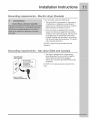
3-wire receptacle
' (NEMA type 10-30R)
ELECTRICAL SHOCK HAZARD
Failure to disconnect power source before servicing
could result in personal injury or even death.
-_ __
\
30 AMP - ' \
',, ,_ NEMA 10-30 _- Neutral
_,, -: : /(center wire)
1•
2.
•
4,
•
Turn off power supply to outlet•
Remove the screw securing the terminal block
access cover in the lower corner on the back of
the dryer.
Install a UUapproved strain relief according
to the power cord/strain relief manufacturer's
instructions in the power cord entry hole below
the access panel• At this time, the strain relief
should be loosely in place.
Thread an UNPLUGGED, UL-approved, 30 amp•
power cord, NEMA 10-30 type SRDT,through the
strain relief•
Attach the power cord neutral (center wire)
conductor to the SILVER colored center
terminal on the terminal block• Tighten the
screw securely•
_ ,- ___--AocessoeVe,sorew
"_-J_S _ -. F T_rminal
L _ _ _ / # / Neutral
t__ \ _/ Line 1
"--___X._-------_ (_RASSterminal/
\,, _ Internal ground
"_- (GREEN screw)
Install
UL=approved
strata rehef here
Terminal screw
recovery slot
•
Attach the remaining two power cord outer
conductors to the outer, BRASS colored
terminals on the terminal block. Tighten both
screws securely•
ELECTRICAL SHOCK HAZARD
Do not make a sharp bend or crimp wiring/
conductor at connections.
7. Follow manufacturer's guidelines for firmly
securing the strain relief and power cord.
8. Reinstall the terminal block cover•
If moving dryer from a 4-wire system and
installing it in a 3-wire system, move the internal
ground from the center terminal back to the
GREEN screw next to the terminal block.
If a terminal screw falls during cord installation,
it can be retrieved in the terminal screw recovery
slot below the access panel.
DO NOT remove
internal ground in
a 3-wire systemll
_li-_ _ ',,t ,,,,,
ii [''
; ,
/ ,,f'
Neutral
terminal

Installation instructions i
4-wire receptacle
I
(NEMA type 14-30R)
I
ELECTRICAL SHOCK HAZARD
Failure to disconnect power source before servicing
could result in personal injury or even death.
'_!_ } N3MOAAI_P30 -____/(GRGEELNnd,re)
--Neutral
WHITE w_re)
1. Turn off power supply to outlet.
2. Remove the screw securing the terminal block
access cover in the lower corner on the back of
the dryer.
3. Install a UL-approved strain relief according
to the power cord/strain relief manufacturer's
instructions in the power cord entry hole below
the access panel. At this time, the strain relief
should be loosely in place.
4. Thread an UNPLUGGED, UL-approved, 30
amp. power cord, NEMA 14-30 type ST or
SRDT, through the strain relief.
5. Disconnect the internal (BLACK) dryer harness
ground wire from the (GREEN) ground screw
next to the terminal block.
6. Attach the ground (GREEN) power cord wire
to the cabinet with the ground (GREEN) screw.
Tighten the screw securely.
7. Move the internal dryer harness ground
(BLACK) wire to the terminal block and attach
it along with the neutral (WHITE) power cord
wire conductor to the center, SILVER colored
terminal on the terminal block. Tighten the
screw securely.
8. Attach the RED and BLACK power cord
conductors to the outer, BRASS colored
terminals on the terminal block. Tighten both
screws securely.
ELECTRICAL SHOCK HAZARD
Do not make a sharp bend or crimp w_ringi
conductor at connections.
9. Follow manufacturer's guidelines for firmly
securing the strain relief and power cord.
10. Reinstall the terminal block cover.
_,'-, I_1 ,i'-", g-_ Install
UL-approved
strain retef here
,, ,,'!"
' Terminal screw
I o , _," recovery slot
_, _ _._--- Access cover
" _----_--'_ . _---Terminal
, J___ "_ _ block
' _ _,' _,
(BRASS terminal)
, "_ Internal ground
"_ (GREEN screw)
If a terminal screw falls during cord installation,
it can be retrieved in the terminal screw recovery
slot below the access panel.
Move internal ground (BLACK)
wire to neutral (SILVER)
terminal for 4-w_re system, "h
(
GREEN
ground screw
GREEN
ground _ re\(,,,,",,,,,
\,,,,
BLACK or
RED power wire
Neutral
terminal
WHITE
neutral wire
/ /"/ BLACK
/ /,," or RED
//_/ power wire
///

'"l installation instructions
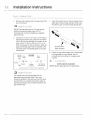
1. Remove the shipping cap from gas pipe at the
rear of the dryer.
DO NOT connect the dryer to LR gas service
without converting the gas valve. An LR
conversion kit must be installed by a qualified
gas technician.
.
Connect a 1/2 inch (1.27 cm) I.D. semi-rigid or
approved pipe from gas supply line to the 3/8
inch (0.96 cm) pipe located on the back of the
dryer. Use a 1/2 inch to 3/8 inch (1.27 cm to
0.96 cm) reducer for the connection. Apply an
approved thread sealer that is resistant to the
corrosive action of liquefied gases on all pipe
connections.
Manual GAS FLOW
Shutoff Flare _ Flare
Valve Union Union
:losed _ J l
,._ Nipple Flexible Inlet Pipeon
Open Connector Back of Dryer
All connections racistbe wrench-tightened
.
4,
Open the shutoff valve in the gas supply line to
allow gas to flow through the pipe. Wait a few
minutes for gas to move through the gas line.
Shutoff Valve-
Open position
Check for gas system leaks with a manometer.
If a manometer is not available, test all
connections by brushing on a soapy water
solution.
" "- d',,, Z ,_[i _rj'_¢
EXPLOSION HAZARD
NEVER test for gas leaks with an open flame.
;,,,_if,, L L_..'" _ '<,__"
The supply line must be equipped with an
approved manual shutoff valve. Th_svalve
should be located in the same room as the dryer
and should be in a location that allows ease of
opening and closing. Do not block access to the
gas shutoff valve.

Installation instructions
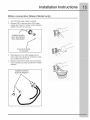
Water connection (Steam Model only}
.
2.
Turn off COLD water supply to washer,
Remove COLD inlet hose from COLD water
supply and inspect for rubber washer. Replace
washer if it is torn or worn out.
RUBBER WASHER
MUST BEPRESENT
AND UNDAMAGED
J
COLD INLET HOSE
TO WASHER
3. Momentarily turn on COLD supply and run
some water into a bucket or container to clear
any contaminants in the line.
4. Remove hose kit from dryer drum and inspect
hose couplings for proper placement of rubber
washers.
J
\
RUBBER WASHERS
MUST BE PRESENT

installation instructions
.
If your installation has room for the COLD
water supply to accept the "Y" connector
directly, thread the "Y" connector to the COLD
water supply and snug it by hand; then tighten
it another 2/3 turn with pliers.
If you were able to install the "Y" connector directly
to the COLD water supply, please skip to step 8.
2. If there is not room to install the "Y" connector
directly, thread the short extension hose on to
the COLD water supply and snug it by hand;
then tighten it another 2/3 turn with pliers.
3. Thread the "Y" connector to the short
extension hose and snug it by hand; then
tighten it another 2/3 turn with pliers.
4. Connect the COLD inlet hose for the washer
to the "Y" connector and snug it by hand; then
tighten it another 2/3 turn with pliers.
5. Connect the straight end of the long hose from
the kit to the other outlet on the "Y" connector
and snug it by hand. Connect the hose's 90°
coupling to the brass water inlet on the back
of the dryer and snug it by hand. Tighten each
connection of the dryer inlet hose another 2/3
turn with pliers.
6. Turn on the water and check for leaks at all
connections.
DIRECT CONNECTION
OR WITH EXTENSION
,-_ _, ,
;.)_ _ _ ER INLE RYEF
COLD WATER SUPPLY
HOSE TO VVASHER

Installation instructions i
,
,
Connect the exhaust duct to the outside
exhaust system (see pages 5 through 7). Use
of a 4" (10.2 cm) clamp is recommended to
connect the dryer to the exhaust vent system.
Use metal foil tape to seal all other joints.
Carefully slide the dryer to its final position.
Adjust one or more of the legs until the dryer is
resting solidly on all four legs. Place a level on
top of the dryer. The dryer MUST be level and
resting solidly on all four legs. Rock alternating
corners to check for stability. Remove and
discard door tape.
<',',_ '_*'_ _, _,,,""_1_'_
Be sure the power is off at a circuit breaker/fuse
box before plugging the power cord into an outlet.
3. Plug the power cord into a grounded outlet.
4. Turn on the power at the circuit breaker/fuse
box.
5. Read the Use & Care Guide provided with
the dryer. It contains valuable and helpful
information that will save you time and money.
6. See the next page about performing a brief,
helpful "Installation Cycle" for your new dryer.
7. If you have any questions during initial
operation, please review the "Avoid Service
Checklist" in your Use & Care Guide before
calling for service.
8. Place these instructions in a location near the
dryer for future reference.
A wiring diagram and technical data sheet are
located inside the dryer console.
Grounding type
wall receptacle
Do not, under
anycircumstances,
cut,remove,
or bypassthe
grounding prong.
Powercord with
3-prong grounded plug
I
I
I
_J

installation instructions
FIRE HAZARD
Before operating the dryer, make sure the dryer
area is clear and free of combustible materials,
gasoline, and other flammable vapors, Also
see that nothing (such as boxes, clothing, etc.)
obstructs the flow of combustion and ventilation air.
- ,j
If your dryer has this console:
1.Empty the dryer drum.
On gas dryers, before the burner will light, it is
necessary for the gas line to be bled of a_r.Ifthe
burner does not light within 45 seconds the first
time the dryer is turned on, the safety switch will
shut the burner off. If this happens, press cancel
and wait 5 minutes before making another
attempt to light.
o'3c : : :
@ O O o
2.After you plug in the dryer the first time: wake up the dryer by pressing any button, rotate cycle knob
to touch up cycle, press the start button and then the cancel button.
3.Wake up the dryer again by pressing any button, then immediately and simultaneously press and hold
both the sanitize and my favorite buttons for 5 seconds, or until the LCD display changes.
4.The LCD window will display llISTRLC21CL_and show estimated time of cycle completion. Press the
start button. The Installation Cycle will automatically test for correct cord connection (on electric mod-
els) and presence of gas supply (on gas models). At cycle completion, the LCD window may display
II",STRLPRSFJ,meaning your new dryer is properly installed and ready for use. If it prompts an action
such as S_R(/_C_CORO,II0 L-,RSor S_,LLS_{IlC_ 877 ff35 3_87, review the installation steps and make the
necessary corrections before you attempt to use the dryer.
5.Your dryer will exit the Installation Cycle and return to normal operation the next time you wake it up.
Dryer will stay awake for 3 minutes after the Installation Cycle. If you wish to
immediately run the dryer through a drying cycle, press the cancel button to put the
unit to sleep and then rewake it immediately to continue the normal operating mode.
6.Please read the Use & Care Guide and enjoy your new premium dryer!
If your dryer has this console: l
1.After you plug in the dryer the first time: wake up the dryer by pressing any button and follow the
prompts on the LCD User Interface, including language selection.
2.The Installation Cycle will automatically test for correct cord connection (on electric models), pres-
ence of gas supply (on gas models) and free flow of exhaust vent. At cycle completion, the LCD user
interface may display II",STRLPRSS;,meaning your new dryer is properly installed and ready for use. If
it prompts an action such as S__-_(/IC_CO°,O,I'_05RSor CRLL.c__-_(/IC_877 u,353287, review the installation
steps and make the necessary corrections before you attempt to use the dryer.
3.Your dryer will exit the Installation Cycle and return to normal operation the next time you wake it up.
Dryer will stay awake for 3 minutes after the Installation Cycle. If you w_shto
immediately run the dryer through a drying cycle, press the cancel button to put the
unit to sleep and then rewake it _mmediately to continue the normal operating mode.
4.Please read the Use & Care Guide and enjoy your new premium dryer!

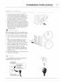
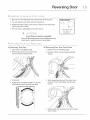
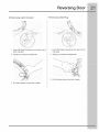
Reversing Door I
1 Be sure you have adequate swing area before reversing door. Tools needed:
2 You will need a screw driver with a #2 square bit. _ \_i_,_-\ //'_'_\
3 Protect flat work surface, such as top of dryer or floor near dryer, 1'___)
with a soft cloth or towel. ___j-/
4 Be sure dryer is unplugged from power source!
ELECTRICAL SHOCK HAZARD
Failure to disconnect power source before serwcing
could result in personal injury or even death.
Screwdrwers with
#2 square &
straight bit
A) Removing Trim Ring B) Removing Door from Front Panel
1 Open door to 90 degree angle. 1 Reopen door to 90 degree angle.
2 Remove and save trim plug and long, 2 Remove 2 short, course-thread, panhead
course-thread, panhead screw, screws.
3
4
Close door.
Rotate door trim approximately _A"counter-
clockwise and pull ring away from door.
E:3 ;"
/ " _ ,/" 'k\
3
4
While supporting door with the other hand,
remove 3 short, fine-thread, counter-sunk
sc rews.
Gently place door face down on flat, covered
work surface.

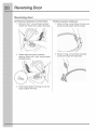
Reversing Door
Reversing door
C) Reversing Hardware on Front Panel
1 Remove 2 short, course-thread, panhead
screws from striker and 2 plastic hole plugs.
Rotate striker and move to opposite
opening. Attach with 2 short, course-thread,
panhead screws.
3 Install original plastic hole plugs or use new
plugs supplied with dryer.
D) Removing Door Hardware
1 Remove 2 long, course-thread, counter-sunk
screws and latch plate. Set latch aside.
Remove 4 long, course-thread, recessed
screws and hinge. Set hinge aside.
\
\
Page is loading ...
Page is loading ...
Page is loading ...
Page is loading ...
Page is loading ...
Page is loading ...
-
 1
1
-
 2
2
-
 3
3
-
 4
4
-
 5
5
-
 6
6
-
 7
7
-
 8
8
-
 9
9
-
 10
10
-
 11
11
-
 12
12
-
 13
13
-
 14
14
-
 15
15
-
 16
16
-
 17
17
-
 18
18
-
 19
19
-
 20
20
-
 21
21
-
 22
22
-
 23
23
-
 24
24
-
 25
25
-
 26
26


Electrolux EWGD65HTS0 Installation guide
- Category
- Electric laundry dryers
- Type
- Installation guide
Ask a question and I''ll find the answer in the document
Finding information in a document is now easier with AI
Related papers
-
Electrolux 134912700 User manual
-
-
Electrolux EFME427UIW User manual
-
-
Electrolux 137064300 B User manual
-
-
Crosley LEQ6400FS0 Installation guide
-
Frigidaire LEQ6000ES0 Installation guide
-
Electrolux EIMED55IMB3 Installation guide
-
Other documents
-
Frigidaire FARE1011MW User guide
-
LG TD-V10055G Owner's manual
-
Frigidaire Affinity FASE7074LW Installation guide
-
-
-
-
-
-
-
Crosley FAQG7011LB0 Installation guide