Page is loading ...

Installation and Operation Manual
X-DPT-EtherCAT-GF1XX-MFC-eng
Part Number: 541B219AAG
April, 2017
Supplemental Manual for
Brooks
®
EtherCAT
®
Mass Flow Controllers
and Meters
GF Series

Installation and Operation Manual
X-DPT-EtherCAT-GF1XX-MFC-eng
Part Number: 541B219AAG
April, 2017
ii
Brooks EtherCAT MFCs

Installation and Operation Manual
X-DPT-EtherCAT-GF1XX-MFC-eng
Part Number: 541B219AAG
April, 2017
iii
Brooks EtherCAT MFCs
Dear Customer,
We recommend that you read this manual in its entirety as this will enable efficient and proper use of the
EtherCAT® thermal mass flow controllers and meters. Should you require any additional information concerning
the EtherCAT thermal mass flow controllers and meters, please feel free to contact your local Brooks Sales and
Service Office; see back cover for contact information, or visit us on the web at www.BrooksInstrument.com. We
appreciate this opportunity to service your fluid measurement and control requirements, and trust that we will be
able to provide you with further assistance in the future.
Yours sincerely,
Brooks Instrument

Installation and Operation Manual
X-DPT-EtherCAT-GF1XX-MFC-eng
Part Number: 541B219AAG
April, 2017
iv
Brooks EtherCAT MFCs
THIS PAGE WAS
INTENTIONALLY
LEFT BLANK

Installation and Operation Manual
X-DPT-EtherCAT-GF1XX-MFC-eng
Part Number: 541B219AAG
April, 2017
v
Brooks EtherCAT MFCs
Contents
1. General Information ................................................................................................................................ 9
1.1. Introduction ................................................................................................................................ 9
1.2. Definition of Terms .................................................................................................................. 10
1.3. Numbers .................................................................................................................................. 10
2. Quick Start .............................................................................................................................................. 11
2.1. Master Hardware ..................................................................................................................... 11
2.2. Physical Interfaces .................................................................................................................. 12
2.2.1. Power Supply .......................................................................................................... 12
2.2.2. LEDs ........................................................................................................................ 13
2.2.3. Exceptions Display Codes and Reporting ............................................................... 15
3. Slave Configuration ............................................................................................................................... 17
3.1. Introduction .............................................................................................................................. 17
3.2. Process Data Object (PDO) Mapping ..................................................................................... 18
3.2.1. RxPDO Mapping ...................................................................................................... 18
3.2.2. TxPDO Mapping ...................................................................................................... 19
3.3. Communication Specific Data ................................................................................................. 21
3.4. Manufacturer Specific Data ..................................................................................................... 22
3.4.1. Manufacturer Specific Inputs ................................................................................... 23
3.4.2. Manufacturer Specific Configuration Data............................................................... 23
3.5. SDP Device Type Specific Data .............................................................................................. 24
3.5.1. Input Data ................................................................................................................ 24
3.5.2. Output Data ............................................................................................................. 25
3.5.3. Configuration Data ................................................................................................... 26
3.5.4. Information Data ...................................................................................................... 27
3.6. Semi Device Profile Area ......................................................................................................... 29
3.7. Value Range Setting ................................................................................................................ 30
3.7.1. Exception Handling Data ......................................................................................... 30
3.8. Manufacturer Specific Device Data ......................................................................................... 32
3.9. SDP and CDP Device Specific Inputs ..................................................................................... 33
3.10. SDP and CDP Device Specific Information Data .................................................................. 33
3.11. SDP and CDP Command Objects ......................................................................................... 35
4. Exceptions Implementation .................................................................................................................. 41

Installation and Operation Manual
X-DPT-EtherCAT-GF1XX-MFC-eng
Part Number: 541B219AAG
April, 2017
vi
Brooks EtherCAT MFCs
4.1. Error and Warning Condition Descriptions .............................................................................. 44
4.1.1. Non-Volatile Memory Failures (Display Codes 1,2,3) ............................................. 45
4.1.2. Network Interface Failure (Display Code 4) ............................................................ 45
4.1.3. Selected Calibration Invalid (Display Code 5) ......................................................... 45
4.1.4. Identity Information Mismatch (Display Code 6) ..................................................... 45
4.1.5. Hardware Incompatibility (Display Code 7) ............................................................. 46
4.1.6. Flow Sensor Failure & Error (Display Code 10 and 110) ........................................ 46
4.1.7. Flow Sensor Cooling Recovery (Display Code 111) ............................................... 46
4.1.8. Excessive Drift (Display Code 112) ......................................................................... 46
4.1.9. Process Flow Out of Range (Display Codes 115 and 116) ..................................... 46
4.1.10. Pressure Sensor Error (Display Code 120) ........................................................... 47
4.1.11. Process Pressure Out of Range (Display Codes 125 and 126) ............................ 47
4.1.12. Temperature Sensor Failure & Error (Display Code 130 and 10) ......................... 47
4.1.13. Temperature Out of Range (Display Codes 135 and 136) .................................... 48
4.1.14. Excessive Leak-By (Display Code 142) ................................................................ 48
4.1.15. Control Deviation Out of Limits (Display Code 145) .............................................. 48
4.1.16. Temperature Stability (Display Code 230) ............................................................ 49
4.1.17. Mounting Orientation Alert (Display Code 251) ..................................................... 49
4.1.18. Voltage Input Out of Limits (Display Code 260) .................................................... 49
4.1.19. Totalizer Overflow Alert (Display Code 270) ......................................................... 49
4.1.20. Warm-up (Display Code 299) ................................................................................ 49
4.1.21. Device ID Switch Changed Alert (No Display Code) ............................................. 50
5. Appendix ................................................................................................................................................ 51
5.1. Ramping Feature ..................................................................................................................... 51

Installation and Operation Manual
X-DPT-EtherCAT-GF1XX-MFC-eng
Part Number: 541B219AAG
April, 2017
vii
Brooks EtherCAT MFCs
Tables
Table 1-1 – Definition of Terms ................................................................................................................... 10
Table 2-1 – RUN Indicator States ................................................................................................................ 14
Table 2-2 – ERROR Indicator States .......................................................................................................... 14
Table 2-3 – Display Code Summary ............................................................................................................ 15
Table 3-1 – Object Dictionary Structure ...................................................................................................... 17
Table 3-2 – Default RxPDO (MFC/EMFC Profiles) ..................................................................................... 19
Table 3-3 – Default RxPDO (MFM/EMFM Profiles) .................................................................................... 19
Table 3-4 – Default TxPDO (EMFC Profile) ................................................................................................ 19
Table 3-5 – Default TxPDO (MFC Profile) ................................................................................................... 20
Table 3-6 – Default TxPDO (MFM Profile) .................................................................................................. 20
Table 3-7 – Default TxPDO (EMFM Profile) ................................................................................................ 20
Table 3-8 – Communication Specific Data .................................................................................................. 21
Table 3-9 – Manufacturer Specific Inputs .................................................................................................... 23
Table 3-10 – Manufacturer Specific Configuration Data ............................................................................. 23
Table 3-11 – Input Data ............................................................................................................................... 24
Table 3-12 – Output Data ............................................................................................................................ 25
Table 3-13 – Configuration Data ................................................................................................................ 26
Table 3-14 – Information Data .................................................................................................................... 27
Table 3-15 – Semi Device Profile ................................................................................................................ 29
Table 3-16 – Value Range Setting .............................................................................................................. 30
Table 3-17 – Manufacturer Specific Device Data ........................................................................................ 32
Table 3-18 – SDP and CDP Device Specific Inputs .................................................................................... 33
Table 3-19 – SDP and CDP Device Specific Information Data ................................................................... 33
Table 3-20 – SDP and CDP Command Objects ......................................................................................... 35
Table 4-1 – Objects for reporting and controlling exceptions ...................................................................... 42
Table 4-2 – Device Errors ............................................................................................................................ 43
Table 4-3 – Manufacturer Errors ................................................................................................................. 43
Table 4-4 – Manufacturer Warnings ............................................................................................................ 44
Table 4-5 – User Specified Flow Limits ....................................................................................................... 46
Table 4-6 – User Specified Pressure Limits ................................................................................................ 47
Table 4-7 – Control Deviation Out of Limits ................................................................................................ 48

Installation and Operation Manual
X-DPT-EtherCAT-GF1XX-MFC-eng
Part Number: 541B219AAG
April, 2017
viii
Brooks EtherCAT MFCs
Figures
Figure 2-1 – Top View of GF EtherCAT Device .......................................................................................... 12
Figure 2-2 – M8 Power Connector Location ................................................................................................ 13
Figure 2-3 – M8 Power Connector Drawing ................................................................................................ 13
Figure 5-1 – Ramping Feature .................................................................................................................... 52

Installation and Operation Manual
X-DPT-EtherCAT-GF1XX-MFC-eng
Part Number: 541B219AAG
April, 2017
9
Section 1 – General Information
Brooks EtherCAT MFCs
1. General Information
1.1. Introduction
EtherCAT is an Ethernet based communication system and is known for its
high cycle time and cost efficient cabling and master application solutions.
Brooks Instrument now introduces the EtherCAT® interface on its GF Series
platform.
This manual is a supplement to the Brooks GF Series installation and
operation manual. It is assumed that the owner of this EtherCAT mass flow
controller or meter is thoroughly familiar with the theory and operation of this
device. If not, it is recommended that the owner read the installation and
operation manual first before continuing with this supplement.
This manual assumes basic knowledge and understanding of EtherCAT (its
topology and its method of logically accessing the data or parameters
contained within the device). This manual is not intended to be a
replacement to the EtherCAT specifications. It is recommended but not
required for the purposes of this manual, that the user obtains a copy of the
EtherCAT specifications (www.ethercat.org).
This manual does not make any assumptions about any particular
manufacturer of equipment or custom software used by the user to
communicate with the Brooks device, but assumes the user has thorough
understanding of such equipment and any configuration software. Application
Notes and FAQ’s are available at the Brooks Instrument web site
(www.BrooksInstrument.com).

Section 1 - General Information Installation and Operation Manual
X-DPT-EtherCAT-GF1XX-MFC-eng
Part Number: 541B219AAG
April, 2017
10
Brooks EtherCAT MFCs
1.2. Definition of Terms
Table 1-1 – Definition of Terms
Abbreviation
Description
CDP
Common Device Profile
CoE
CAN Application Protocol over EtherCAT
ESC
EtherCAT Slave Controller
ESI
EtherCAT Slave Information (EtherCAT Device Description)
ETG
EtherCAT Technology Group
MFC/MFM
Mass Flow Controller/Mass Flow Meter
OD
Object Dictionary
PDO
Process Data Object
PreOp
Pre-Operational
RO
Read Only
RW
Readable and Writable
RXPDO
Receive PDO
SDP
Specific Device Profile
SI
Sub-Index
TXPDO
Transmit PDO
WO
Write Only
1.3. Numbers
Numeric values used throughout this manual will be clearly denoted as to the
base numeric system it represents. All hexadecimal numbers (base 16) will
be prefixed with a 0x, like 0xA4. All binary numbers (base 2) will be suffixed
with a b, like 1001b. All other numbers not annotated this way will be
assumed decimal (base 10).

Installation and Operation Manual
X-DPT-EtherCAT-GF1XX-MFC-eng
Part Number: 541B219AAG
April, 2017
11
Section 2 - Quick Start
Brooks EtherCAT MFCs
2. Quick Start
This section assumes the owner of the device has a fully operational and
trouble-free communications network with appropriate power supplies. This
section also assumes that an EtherCAT master application is connected to
the network capable of PDO and mailbox data communication. Both types of
data communication modes are supported by the Brooks GF EtherCAT
device.
Brooks® GF Series Mass Flow Controllers and Meters conform to the
ETG.5003 Semiconductor Device Profile specification. This specification
consists of two parts:
Part 1: Common Device Profile
The Common Device Profile (CDP) specifies requirements applicable to all
devices described in the Specific Device Profiles. Furthermore, it describes
features and functionalities which shall be further defined in the Specific
Device Profiles.
Part 2xxx: Specific Device Profiles
The Specific Device Profile (SDP) is based on Part 1 (CDP) and defines the
data structure of the specific devices. The Brooks GF1XX Series
implementation of the Semi EtherCAT SDP conforms to ETG.5003.202x.
For a complete specification of a device used in the semiconductor
manufacturing industry a SDP shall be read complementary with the CDP.
Users may obtain a copy of the EtherCAT specifications at
(www.ethercat.org).
2.1. Master Hardware
Various companies provide EtherCAT master applications, e.g. TwinCAT
from Beckhoff, or offer EtherCAT master stacks to develop a master
application, e.g. Acontis. A PC can be used to run most EtherCAT master
applications but needs dedicated Ethernet hardware to support the high cycle
times and kernel mode operation of the master application, see
(www.beckhoff.com).

Installation and Operation Manual
X-DPT-EtherCAT-GF1XX-MFC-eng
Part Number: 541B219AAG
April, 2017
12
Section 2 - Quick Start
Brooks EtherCAT MFCs
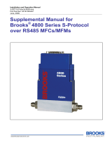
2.2. Physical Interfaces
The available physical interfaces on the EtherCAT device are listed below.
Refer to the GF100 Series Installation and Operation Manual for more
details.
Integrated LCD display
Display push button- cycle through information and rotate display
Zero push button- easily re-zero the device
Micro-USB Diagnostic Port
Twin RJ45 external top mounted communication connections
5-pin M8 threaded male connector for power located on upper inlet side
2.2.1. Power Supply
Power needs to be supplied via the standard male M8 5-pin connector. The
M8 connector is located on the upper inlet side of the device. Refer to
Figures 2-2 and 2-3 below.
Figure 2-1 – Top View of GF EtherCAT Device

Installation and Operation Manual
X-DPT-EtherCAT-GF1XX-MFC-eng
Part Number: 541B219AAG
April, 2017
13
Section 2 - Quick Start
Brooks EtherCAT MFCs
Figure 2-2 – M8 Power Connector Location
Figure 2-3 – M8 Power Connector Drawing
Pin 1: +24V
Pin 3: Power Common
2.2.2. LEDs
The POWER LED indicates that the device is supplied sufficiently with
power.
The IN and OUT port LEDs indicate whether the respective removable port is
connected.
The RUN indicator shows the status of the EtherCAT State Machine. Refer to
Table 2-1 below for indicator states and descriptions.

Installation and Operation Manual
X-DPT-EtherCAT-GF1XX-MFC-eng
Part Number: 541B219AAG
April, 2017
14
Section 2 - Quick Start
Brooks EtherCAT MFCs
Table 2-1 – RUN Indicator States
Indicator States
Slave State
Description
Off
INITIALIZATION
The device is in state INIT
Blinking
PRE-OPERATIONAL
The device is in state PRE-OPERATIONAL
Single Flash
SAFE-OPERATIONAL
The device is in state SAFE-OPERATIONAL
On
OPERATIONAL
The device is in state OPERATIONAL
Flickering
BOOTSTRAP
The device is in state BOOTSTRAP. Firmware download
operation in progress
The ERROR indicator shows errors such as watchdog timeouts and
unsolicited state changes due to local errors (ex. input error). If, at a given
time several errors are present, the error that occurred first shall be
indicated. Refer to Table 2-2 below for error states and descriptions.
Table 2-2 – ERROR Indicator States
ERR State
Error Name
Description
Example
On
Application controller
failure
A critical communication or
application controller error
has occurred
Application controller is not
responding any more (PDI
Watchdog Timeout detected by
ESC)
Double Flash
Process Data
Watchdog Timeout/
EtherCAT Watchdog
Timeout
An application watchdog
timeout has occurred.
Sync Manager Watchdog
timeout
Single Flash
Local Error
Slave device application has
changed the EtherCAT state
autonomously, due to local
error (see ETG.1000 part 6
EtherCAT State Machine).
Error Indicator bit is set to 1
in AL Status register.
Device changes its EtherCAT
state from Op to SafeOpError
due to a synchronization error.
Blinking
Invalid Configuration
General Configuration Error
State change commanded by
master is impossible due to
register or object settings, or
invalid hardware configuration
(pin sharing violation detected by
ESC)

Installation and Operation Manual
X-DPT-EtherCAT-GF1XX-MFC-eng
Part Number: 541B219AAG
April, 2017
15
Section 2 - Quick Start
Brooks EtherCAT MFCs
Flickering
Booting Error
Booting Error was detected.
INIT state reached, but Error
Indicator bit is set to 1 in AL
Status register
Checksum error in Application
controller flash memory.
Off
No error
The EtherCAT
communication of the device
is in working condition
2.2.3. Exceptions Display Codes and Reporting
Whenever there is an active Error or Warning reported via the EtherCAT
interface, that condition is also indicated on the display with the severity and
the Display Code as defined in Table 2-3. When more than one condition
exists, then the most severe condition will be displayed. The display will
show the following information in the specified sequence:
1. Normal selected information for 3 seconds;
2. Severity (“FAIL”, “ERR”, or “ALrT”) for 1 second;
3. Display Code for 1 second.
The display of any Error or Warning can be disabled individually via
EtherCAT object 0x400B and via the diagnostic port. See Table 2-3.
For more detailed information on individual conditions, see Section 4 on
Exceptions Implementation.
Table 2-3 – Display Code Summary
Display
Code
Condition Detected
Reported As
Severity
Exception Type
1
Non-Volatile Failure
0x40000000
Failure
Manufacturer Error
2
Non-Volatile Corrupt
0x20000000
Failure
Manufacturer Error
3
Non-Volatile Write Failure
0x10000000
Failure
Manufacturer Error
4
Network Interface Failure
0x08000000
Failure
Manufacturer Error
5
Selected Calibration Invalid
0x04000000
Failure
Manufacturer Error
6
Identity Information Mismatch
0x02000000
Failure
Manufacturer Error
7
Hardware Incompatibility
0x00000800
Failure
Manufacturer Error
10
Sensor Failure
0x80000000
Failure
Manufacturer Error
110
Flow Sensor Error
0x00800000
Error
Manufacturer Error
111
Flow Sensor Cooling
Recovery
0x00080000
Error
Manufacturer Error
112
Excessive Flow Sensor Drift
0x00040000
Error
Manufacturer Error
115
Process Flow Out of Range
0x00000001
Error
Manufacturer Error

Installation and Operation Manual
X-DPT-EtherCAT-GF1XX-MFC-eng
Part Number: 541B219AAG
April, 2017
16
Section 2 - Quick Start
Brooks EtherCAT MFCs
High
116
Process Flow Out of Range
Low
0x00000002
Error
Manufacturer Error
120
Pressure Sensor Error
0x00400000
Error
Manufacturer Error
125
Process Pressure Out of
Range High
0x00000004
Error
Device Error
126
Process Pressure Out of
Range Low
0x00000008
Error
Device Error
130
Temperature Sensor Error
0x00200000
Error
Manufacturer Error
135
Temperature Out of Range
High
0x00000001
Error
Device Error
136
Temperature Out of Range
Low
0x00000002
Error
Device Error
142
Excessive Leak-By
0x00020000
Error
Manufacturer Error
145
Process Control Deviation
0x00000004
Error
Manufacturer Error
230
Temperature Stability
0x00400000
Alert
Manufacturer Warning
251
Mounting Orientation
0x00200000
Alert
Manufacturer Warning
260
Input Voltage Out of Range
0x00100000
Alert
Manufacturer Warning
270
Totalizer Overflow
0x00080000
Alert
Manufacturer Warning
299
Warm Up
0x00800000
Alert
Manufacturer Warning
None
Device ID Switch Changed
0x00040000
Alert
Manufacturer Warning

Installation and Operation Manual
X-DPT-EtherCAT-GF1XX-MFC-eng
Part Number: 541B219AAG
April, 2017
17
Section 3 - Slave Configuration
Brooks EtherCAT MFCs
3. Slave Configuration
3.1. Introduction
Based on the information provided by the EtherCAT Slave Information file
(ESI, device description in XML format) and/or the EEPROM, master
applications are able to configure the EtherCAT network. For the EtherCAT
network configuration of the GF Series devices, ESI files are provided on the
Brooks website or contact Brooks Technical Support for more info.
The following table outlines the structure of the object dictionary and is
divided into index areas as defined by ETG.5003. Not all index areas have
objects defined within them, as demonstrated in the sections to follow.
Table 3-1 – Object Dictionary Structure
Index
Object
0x0000…0x0FFF
Data Type Area
0x1000…0x1FFF
Communication Specific Data
0x2000…0x5FFF
Manufacturer Specific Data incl. Customer Requested Data
0x2000 – 0x200B
Manufacturer Specific Inputs
0x200C – 0x200F
Customer Requested Inputs
0x3000 – 0x300B
Manufacturer Specific Outputs
0x300C – 0x300F
Customer Requested Outputs
0x4000 – 0x400B
Manufacturer Specific Configuration Data
0x400C – 0x400F
Customer Requested Configuration Data
0x5000 – 0x500B
Manufacturer Specific Information Data
0x500C – 0x500F
Customer Requested Information Data
0x6000…0xAFFF
(SDP) Device Type Specific Data
0x600x
Input Data of the Modules
0x700x
Output Data of the Modules
0x800x
Configuration Data of the Modules
0x900x
Information Data Modules
0xA00x
Diagnosis Data of the Modules
0xF0xx
Semiconductor Device Profile Area
0xF300
Value Range Setting
0xF38x…0xF3Ax
Exception Handling Data
0xF5xx
Manufacturer Specific Device Data incl. Customer Requested Data
0xF6xx
SDP and CDP Device Specific Inputs
0xF7xx
SDP and CDP Device Specific Outputs
0xF8xx
SDP and CDP Device Specific Configuration Data
0xF9xx
SDP and CDP Device Specific Information Data

Installation and Operation Manual
X-DPT-EtherCAT-GF1XX-MFC-eng
Part Number: 541B219AAG
April, 2017
18
Section 3 – Slave Information
Brooks EtherCAT MFCs
0xFAxx
SDP and CDP Device Specific Diagnosis Data
0xFBxx
SDP and CDP Command Objects
3.2. Process Data Object (PDO) Mapping
Process Data Object Mapping defines the data that is exchanged between
the Master and the device using high speed data exchange. RxPDO
Mapping defines the data that is sent from the Master to the device and
TxPDO Mapping defines the data that is sent from the device to the Master.
Note that the Master normally refers to RxPDO as Outputs and the TxPDO
as Inputs.
During network configuration, the user must configure the data to be
exchanged. The Brooks GF1xx Series devices provide a default and a
flexible PDO Mapping object for each of the RxPDO and the TxPDO. The
user may select either the default or the flexible PDO Mapping, or both by
using the PDO Assignment objects 0x1C12 and 0x1C13.
Each flexible PDO Mapping may be configured with up to 10 objects.
Objects assigned to a PDO Mapping must have the appropriate PDO access
permission (see the Access column in the object definition tables). Mapping
an object requires the user to specify the object’s index, sub index, and size
in bits in the PDO Mapping object. Objects with a data type that is not a
multiple of 8 bits may require that a “pad” object be included so that the next
object starts on an 8-bit boundary. An example of a data type that is not a
multiple of 8 bits is the bool data type (1 bit). A pad object has an object
number of 0x0000:00 with a non-zero bit size. The pad object counts as one
of the 10 objects that can be configured. It is best practice to group objects
that are not a multiple of 8 bits so that only 1 pad is required.
PDO mappings are sent from the Master to the device while the device is in
PREOP state. If the PDO mappings are not properly configured, the device
will return an error when requested to transition to the SAFEOP state. The
Error LED will flash RED and the resulting device state will be ERRPREOP.
3.2.1. RxPDO Mapping
The Brooks GF1xx Series device supports one preconfigured, default
RxPDO at 0x1600 and one user configurable RxPDO at 0x1601.
The default RxPDO for each device profile are defined in the tables below:

Installation and Operation Manual
X-DPT-EtherCAT-GF1XX-MFC-eng
Part Number: 541B219AAG
April, 2017
19
Section 3 - Slave Configuration
Brooks EtherCAT MFCs
Table 3-2 – Default RxPDO (MFC/EMFC Profiles)
PDO Index
PDO Sub Index
PDO Entry
Index
PDO Entry Sub
Index
Bit Length
Name
0x1600
0x01
0x7003
0x01
32
Flow SP [REAL]
0x02
0x7009
0x01
8
Actuator Control
0x03
0x7009
0x02
32
Actuator
Position SP
[REAL]
See Note below.
0x04
0x7008
0x01
32
Ramp Time
Table 3-3 – Default RxPDO (MFM/EMFM Profiles)
PDO Index
PDO Sub Index
PDO Entry
Index
PDO Entry Sub
Index
Bit Length
Name
-
-
-
-
-
-
Note: The Actuator Position SP functionality is not supported in GF1XX devices. However, the space must be
included in this RxPDO to maintain compatibility with the ETG.5003.202x profile definition. Any value placed in
this position is ignored. If the user wishes to eliminate this space, the Flexible RxPDO can be used.
The following limitations apply to the flexible RxPDO (0x1601):
Any PDO entry from the dynamic or the default PDO may
only exist once. Setpoint (which can either be real or
integer) can only be declared once. If an entry is
declared more than once, or any other PDO definition
fault exists (bad gap, invalid entry, etc.), the device will
not exit pre-op.
All objects assigned to active RxPDO will be Read-Only
when accessed via COE Mailbox.
3.2.2. TxPDO Mapping
The Brooks GF1xx Series device supports one preconfigured, default TxPDO
at 0x1A00 and one user configurable TxPDO at 0x1A01.
The default TxPDO for each device profile are defined in the tables below:
Table 3-4 – Default TxPDO (EMFC Profile)
PDO Index
PDO Sub Index
PDO Entry
Index
PDO Entry Sub
Index
Bit Length
Name

Installation and Operation Manual
X-DPT-EtherCAT-GF1XX-MFC-eng
Part Number: 541B219AAG
April, 2017
20
Section 3 – Slave Information
Brooks EtherCAT MFCs
0x1Ann
0x01
0xF380
0x00
8
Active Exception
Status
0x02
0x6000
0x01
32
Flow Reading
[REAL]
0x03
0x6001
0x01
32
Pressure
Reading [REAL]
0x04
0x6002
0x01
32
Temperature
Reading [REAL]
0x05
0x6009
0x02
32
Position Read
back [REAL]
See Note below.
0x06
0x6009
0x01
32
Position Set
point [REAL]
Table 3-5 – Default TxPDO (MFC Profile)
PDO Index
PDO Sub Index
PDO Entry
Index
PDO Entry Sub
Index
Bit Length
Name
0x1Ann
0x01
0xF380
0x00
8
Active Exception
Status
0x02
0x6000
0x01
32
Flow Reading
[REAL]
0x03
0x6009
0x01
32
Position Set
point [REAL]
Table 3-6 – Default TxPDO (MFM Profile)
PDO Index
PDO Sub Index
PDO Entry
Index
PDO Entry Sub
Index
Bit Length
Name
0x1Ann
0x01
0xF380
0x00
8
Active Exception
Status
0x02
0x6000
0x01
32
Flow Reading
[REAL]
Table 3-7 – Default TxPDO (EMFM Profile)
PDO Index
PDO Sub Index
PDO Entry
Index
PDO Entry Sub
Index
Bit Length
Name
0x1Ann
0x01
0xF380
0x00
8
Active Exception
Status
0x02
0x6000
0x01
32
Flow Reading
[REAL]
0x03
0x6001
0x01
32
Pressure
Reading [REAL]
0x04
0x6002
0x01
32
Temperature
Reading [REAL]
Note: Position Read back [REAL] functionality is not supported in GF1XX devices. However, the space must be
included in this TxPDO to maintain compatibility with the ETG.5003.202x profile definition. The value of this
object is always returns as 0.0. If the user wishes to eliminate this space, the Flexible TxPDO can be used.
The following limitations apply to the flexible TxPDO (0x1A01):
/