American Megatrends Video Gaming Accessories MAN-940-QH User manual

Type
User manual

This manual is also suitable for

Quick Hardware Installation Guide
English
MAN-940-QH
01-04-07
MegaRAC G4 card
(Series 940)
Thank you for purchasing the MegaRAC G4 card. Please take a few minutes to
review this quick guide before beginning the installation process. If you require a
further explanation of any item covered in this guide, please refer to the installation
instructions on your MegaRAC G4 CD.
Contents for the MegaRAC G4 card
You should have received the following:
an American Megatrends MegaRAC® G4 card
a MegaRAC® G4 card Quick Installation Guide
this MegaRAC® G4 User’s Guide (located on the MegaRAC® G4 CD)
a MegaRAC® G4 CD
a VGA Splitter Cable
a MegaRAC G4 USB Cable with a power jack input for the AC Adapter
MegaRAC® G4 feature connector cable
an AC Adapter (Optional)
Technical Support
If you need help installing, configuring, or running the MegaRAC G4 card, call
American Megatrends technical support at 770-246-8645.
Technical Support Web Site: http://www.ami.com/support/
Technical Support Email: [email protected]
Hardware Installation
Use the following steps to install the MegaRAC G4 card.
Step Action
1 Unpack the MegaRAC G4 card (and check jumper settings)
2 Plug in the MegaRAC G4 card into the host system and attach internal
cables
3 Connect external cables
4 Confirm the motherboard’s BIOS settings
5 Initial configuration of the MegaRAC G4 card
6 Install/Boot to an Operating System
Note: The AC Adapter (optional) continues to provide power to the MegaRAC
card in the event that the host system is on standby mode (3.3V STB) or
powered on.
Step 1 Unpack the MegaRAC G4 card (and check jumper settings)
Inspect the cardboard carton for obvious damage. If damaged, call 770-246-8600.
Leave it in its original packing.
Jumper Setting
J5 Confirm that no jumper is installed (pins one and two, open).
J14 & J15 If your hosts system’s motherboard has support for I2C on the PCI slots,
place a short pins one and two. If not, confirm that no jumper is installed
(pins one and two, open).
J16 & J17 Verify that these two headers are each shorted with a jumper. If J16 and J17
are not shorted, short pins one and two on both J16 and J17.
Note: J14 and J15 can be used in place of the MegaRAC Feature Cable to gather
I2C bus information from the motherboard.
MegaRAC G4 Card Layout and Connection Guide
USB In
Network
VGA In
J10 RS232 Serial Port
J5 Recovery/ Configuration
J18 MegaRAC Feature Connector
J16 & J17 Must Be Shorted
J14 & J15 I2C Clock/Data PCI Bypass
Host System’s Motherboard PCI Slot
VGA Splitter Cable
RJ-45 Network Cable
Plug the AC Adapter here (optional)
To the MegaRAC G4
(USB In)
To Host System’s USB Port
Power On Cable
(Runs between
the MegaRAC G4
and the Power On
Switch located
on Front Panel of
the Host System)
Power On Cable
(Runs between the
MegaRAC G4 and the
Power On Header located
on the Host System’s
Motherboard)
Reset Switch Cable
(Runs between
the MegaRAC G4
and the Reset
Switch located
on Front Panel of
the Host System)
Reset Switch Cable
(Runs between
the MegaRAC G4
and the Reset
Header located
on the Host
System’s
Motherboard)
I2C Cable
(Optional, with Limitations. Runs between the
MegaRAC G4 and the IPMB Header located
on the Host System’s Motherboard)
To the Monitor
(15-pin Female)
To the MegaRAC G4
(15-pin Female)
To the Host System’s
VGA Port
(15-pin Male)
MegaRAC Feature
Connector Cable
(not to drawn to scale)
Step 2 Plug in the MegaRAC G4 card into the Host System and Attach Internal Cables
Physically plug in the MegaRAC G4 card into any available PCI slot inside the host system.
Connector Description
J10 Serial Port You can connect an external 9 pin serial port connector to this header. This header is primarily used to text redirect over the serial port.
J18 MegaRAC® Feature Connector Inspect the MegaRAC Feature Connector Cable. There are six connectors on the MegaRAC Feature Connector Cable. One side has one connector and it plugs into
the MegaRAC card. The other end has a “Power On” pair, “Reset Switch” pair and an I2C connector. The “Power On” pair allows you to control the power on your
host system. The “Reset Switch” pair also allows you to reset the host system. These two pair of cables allows you to maintain you host system’s power and reset
switch functionality. Connect them according to the illustration above.
OEM FEATURE ONLY: The I2C connector attaches to your motherboard’s I2C port (Hardware Health Monitoring port). The pin-out of the I2C port varies from
motherboard to motherboard. Also the name of the I2C port varies. It may be listed as an IPMI or IPMB port. Your motherboard may not have this port at all.
Instead, it may have its Hardware Health Monitoring (I2C Clock and I2C) Data routed through the PCI slot. In this case, use the jumpers at J14 and J15. If your
motherboard does not have Hardware Health Monitoring support, tie this cable so that it does not come into contact with anything inside the chassis. The I2C
connector requires that you have a Sensor Definition Kit (SDK/SDR.DAT) file created along with a Soft Processor (SP.DAT) file. These two files tell the MegaRAC
software what it is monitoring.
Quick Hardware Installation Guide
English
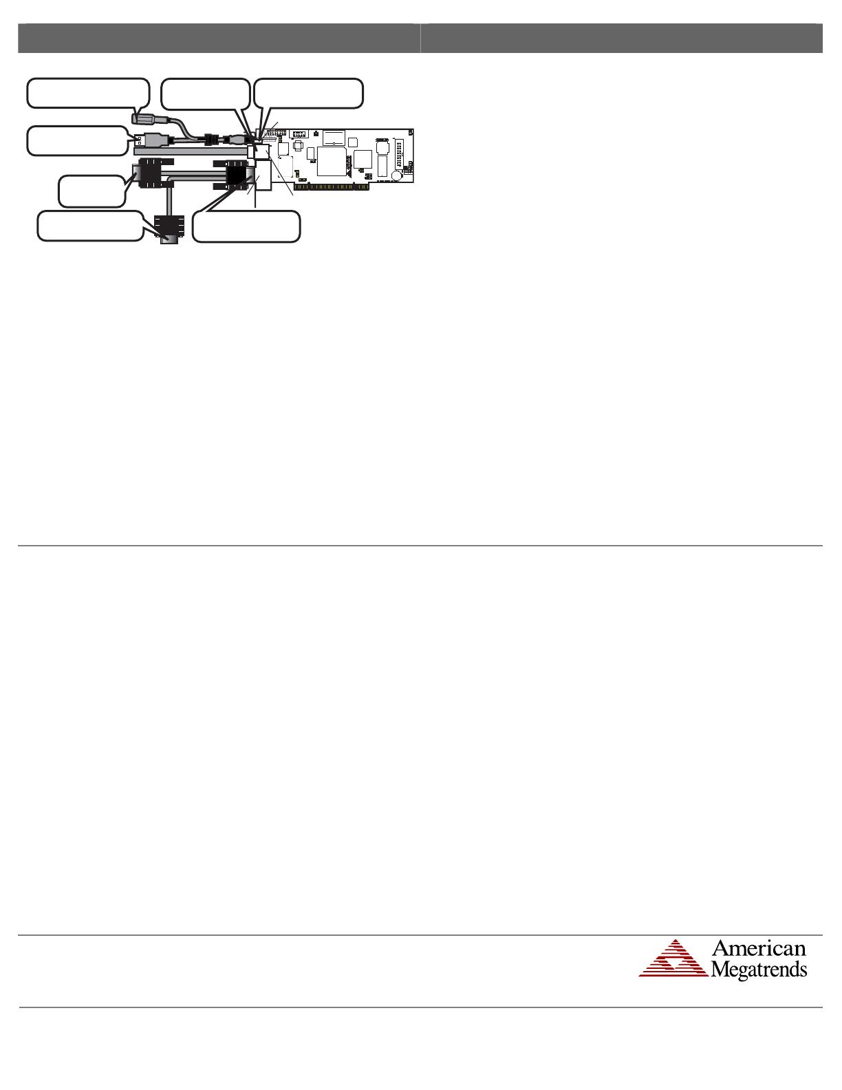
Step 3 Connect External Cables
Connect the MegaRAC G4
USB cable to the card.
(Optional) Connect the Power
Adapter to the card.
Connect to the USB Port
on the Host System.
Connect to the VGA port
on the Host System.
Connect the VGA Splitter
Cable to the card.
Connect to the
local Monitor.
Connect the Network
Cable to the card.
USB In
Network
VGA In
Attach the VGA splitter to the MegaRAC® G4 card. Connect the female end to the
monitor and the male end to your host system’s VGA port.
Connect the RJ45 LAN cable from your local network to your MegaRAC® G4 card.
Connect the MegaRAC G4 USB cable from your host system’s USB port to you
MegaRAC® G4 card.
Connect your AC adapter to the MegaRAC G4 USB cable.
Note: The AC Adapter (optional) continues to provide power to the MegaRAC card in the
event that the host system is on standby mode (3.3V STB) or powered on.
Step 4 Confirm the Motherboard’s BIOS Settings
Power on the motherboard and enter the BIOS. Using the following table, confirm that your
motherboard’s BIOS settings are correct.
BIOS Section Setting
Boot Options> Removable Devices AMI Virtual Floppy or USB Boot Device
Boot Options> ATAPI CDROM AMI Virtual CDROM or USB Boot Device
Advanced> PCIPnP> Configuration> Enable
Legacy USB Support
Save the BIOS settings and restart the computer.
Note: Make sure that your motherboard BIOS supports Legacy USB devices, USB Boot or
Boot to USB.
Note: On some motherboards and server boards, depress the <CTRL>, <ALT>, and <ESC>
keys simultaneously to enter the BIOS. On others use the <F2> keys. See your server’s
documentation for more information on entering the BIOS setup.
Step 5 Initial Configuration of the MegaRAC G4 card
The MegaRAC® G4 card is ready to be used at this stage. If you have an AC Adapter
attached to the MegaRAC® G4 card’s USB cable, it will be powered on even if your
host system is not powered on.
At this point you may wish to do an initial configuration of the MegaRAC® G4 card in
order to find its IP Address.
You can access the MegaRAC® G4 card from another system via the network. AMI
refers to this other system as the client system. To do this, you must know the
MegaRAC® G4 card’s IP Address. If you have installed the MegaRAC® G4 card on a
network that uses DHCP, you can search the network for the MegaRAC® G4 card. To
locate and find out its IP Address, run the G4ConfigApp Utility located on your CD.
G4ConfigApp
The MegaRAC card can be located using the G4ConfigApp utility. Once the IP Address
is located or configured, you can use your Internet browser to access the MegaRAC
card remotely. The G4ConfigApp utility is a GUI-based program that must be run from
the host machine. The host machine is the computer that has the MegaRAC card
installed in it.
To run the G4ConfigApp program, double left click the G4ConfigApp.exe icon
located in the following directories on your MegaRAC™ G4 CD:
CDROM\ServerAgent\Windows\
The G4ConfigApp Dialog window will appear. When prompted for the user name and
password, use root for the User Name and superuser for the Password. Both are
all lower-case characters. Once logged in, you will be able to get the MegaRAC card’s
current network information.
Step 5 Initial Configuration of the MegaRAC G4 card , Continued
Note: When you log in using the root user name and password, you have full
administrative powers. It is advised that once you log in, you change the
root password.
Setup your Client System’s Internet Browser
You must first set up Internet Explorer browser on the client system before you can
redirect the host system’s console. Set up Internet Explorer’s Security Settings to allow
the downloading of Signed ActiveX controls and also allow it to run Signed ActiveX
controls. See the MegaRAC G4 User’s Guide located on the MegaRAC G4 CD for
more information.
Note: At the time this document was being created, the MegaRAC ActiveX
controls were in the process of being “signed” (by VeriSign®) so that they
could be authenticated by Internet browsers. If redirection does not operate
properly, you may have to set up Internet Explorer’s Security Settings to
allow the downloading of Unsigned ActiveX controls and also allow it to run
Unsigned ActiveX controls as well.
Step 6 Install/Boot to an Operating System
At this stage if you already have an operating system loaded on the host system, you
can boot to it. While the operating system is booting up, it will detect the MegaRAC
G4 card’s USB devices (that make device redirection possible).
The operating system will default to the standard drivers for all devices. If you are
running Linux on your host system, it will continue to use default drivers.
AMI Corporate Headquarters
American Megatrends Inc.
6145-F Northbelt Parkway,
Norcross, Georgia 30071-2976
Sales (800)828-9264 sales@ami.com
Main (770)246-8600 Fax (770)246-8790
www.ami.com
®
2007 American Megatrends Inc. All Rights Reserved. Printed in the U.S.A.
  • Page 1 1
  • Page 2 2

American Megatrends Video Gaming Accessories MAN-940-QH User manual

Type
User manual
This manual is also suitable for

Ask a question and I''ll find the answer in the document

Finding information in a document is now easier with AI