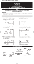
Litetronics EB40 Installation guide

Type
Installation guide

The Litetronics EB40 is an LED Emergency Battery Backup unit designed to provide 90 minutes of emergency power to LED fixtures during power outages, ensuring continued illumination in critical areas. Fully charges in 24 hours and remains in standby mode, with the indicator light staying on. The unit includes a charging indicator test switch for easy monitoring and testing. Self-testing function performs a 30-second discharge test monthly and a full discharge test annually. Compatible with all LED fixtures below 300W, including those with 0-10V dimming capabilities for fixtures above 40W.

The Litetronics EB40 is an LED Emergency Battery Backup unit designed to provide 90 minutes of emergency power to LED fixtures during power outages, ensuring continued illumination in critical areas. Fully charges in 24 hours and remains in standby mode, with the indicator light staying on. The unit includes a charging indicator test switch for easy monitoring and testing. Self-testing function performs a 30-second discharge test monthly and a full discharge test annually. Compatible with all LED fixtures below 300W, including those with 0-10V dimming capabilities for fixtures above 40W.

LED Emergency Battery Backup
Installation Instructions
Ordering Code: EB40
WHAT COMES IN THE BOX
(1) EB40 unit
(1) Installation instructions
(1) Charging indicator test switch with 2 screws
(1) Test switch cover
(2) Waterproof nuts
(1) Remote control
(11) Wire nuts
TOOLS NEEDED
Wire stripper
Wire cutter
Phillips screwdriver
Step ladder
2
SAFETY WARNING AND INSTRUCTIONS
When using electrical equipment, basic safety precautions should always be observed.
Read and follow all safety instructions.
Risk of fire or electric shock. Luminaire wiring and electrical parts may be damaged when drilling for
installation of LED Emergency Backup. Check for enclosed wiring and components.
Risk of fire or electric shock. This LED Emergency Backup installation requires knowledge of luminaire
and electrical systems. If not qualified, do not attempt to install. Contact a qualified electrician.
Before installation, make certain the AC power to the fixture is off.
The electrical rating of this product is 100-347V Vac. Installer must confirm that there is 100-347V Vac to the
fixture before installation.
To prevent electrical shock, only mate unit connector after installation is complete and before the AC power
to the fixture is back on.
Do not use outdoors.
This LED Emergency Backup unit requires an un-switched AC power source of 100-347V Vac, 50/60Hz.
Do not let power supply cords touch hot surfaces.
Do not mount near gas or electric heaters.
Equipment should be mounted in locations and at heights where it is not subjected to tampering by
unauthorized personnel. The use of accessory equipment is not recommended by the manufacturer and
may cause an unsafe condition.
Do not use this equipment for other than its intended use - only use for LED Lighting emergency backup.
Use with grounded, UL/ETL listed, dry or damp location rated fixtures.
CAUTION: The EB40 provides more than one power supply output source. To reduce the risk of electrical shock,
disconnect both normal and emergency source by turning off the A.C. branch circuit.
CAUTION: Servicing of this equipment should be performed by qualified personnel only.
CAUTION: Do not attempt to service the battery. A sealed, no-maitenence battery is used that is not field
replaceable. Replace the entire unit when necessary.
CAUTION: The use of accessory equipment not recommended by the manufacturer may cause an unsafe
condition, void warranty, and result in non-compliance with UL specifications.
For use in 32°F minimum, to 12F maximum ambient temperatures. Suitable for use in damp locations
and plenum spaces.
Not for use in heated air outlets or hazardous locations.
COMPATIBILITY
The EB40 is compatible with all LED fixtures less than 300W. All fixtures must also include 0-10V
dimming if wattage is greater than 40W.
PLEASE NOTE: Although tested and compliant with UL924, when used with a sensor-equipped
fixture, unless the sensor wiring is accessible and bypassed, the sensor settings will remain active,
overriding the EB40 emergency power to the fixture, and cause the fixture to dim or turn off based on
its occupancy programming. This may not be ideal during emergency egress and may not meet code
requirements. We recommend that if the EB40 is used on a sensor-equipped fixture, the sensor be
programmed to maintain full light output when occupancy sensing or daylight harvesting is active.
3
EB40 OPERATING INSTRUCTIONS
Litetronics Emergency Battery Backup unit (EB40) delivers 90-minutes of power to fixtures in
the event of a power outage.
Once installed and receiving power, the unit will charge fully and remain in stand-by mode,
and the indicator light will remain on.
INDICATOR LIGHT
In AC operation, the indicator light will remain on/solid
In emergency operation, the light will flash slowly (on for 2 seconds,
off for 2 seconds)
If a failure were to occur, the light will flash quickly (on for 0.2 seconds,
off for 0.2 seconds)
The Indicator Light / Test Switch may be mounted on a switch box near the
fixture. Although easy accessibility is not required, it must be visible to
occupants.
The Red Button/Indicator Light is required via Class 2 wiring to enable full
functionality of the EB40.
TEST SWITCH
In AC operation, press the test button once to conduct a 30 second emergency test
In AC operation, press the test button twice (in 2 seconds timespan)
to conduct a 90-minute full discharge test.
During emergency operation, press the test switch once to shut off the unit
REMOTE TEST SWITCH
In AC operation, press test button A once to conduct a 30 second
emergency test
In AC operation, press test button B once (in 2 seconds timespan)
to conduct a 90-minute full discharge test.
During emergency operation, press the test switch once to shut off the unit
Range - With the antenna extended, the range will be up to 40.
AUTOMATIC SELFTESTING
The EB40 includes a self-testing function, which will perform a 30-second discharge test once
a month and a full discharge test one a year. At this time, the unit will simulate an AC power
failure and automatically switch to emergency mode. During routine testing, the unit will
monitor the operation of the LED load, battery voltage, an emergency duration. If the unit
detects any problems, the indicator light will flash quickly.
MAINTENANCE
Although no routine maintenance is required to keep the emergency battery backup functional,
it should be checked periodically to ensure that it is working. The following schedule is recom-
mended:
Visually inspect the charge indicator light monthly. It should be illuminated.
Test the emergency operation of the fixture at 30-day intervals for a minimum of 30 seconds.
Conduct a 90-minute discharge test once a year. LED fixture should operate at up to 40W for
at least 90 minutes.
SERVICE
Should be performed as indicated above by qualified personnel.
A
B
30 SECONDS
90 MINUTES
Operation Manual for Remote Test Switch
Pictures: Size:
92MM
40MM
antenna
test button A
test button B
1,Remote Test Switch: Signal distance 33 Ft
Features:
2,One test switch could control as many as EM pack,
as long as they are within the range of 33 feet.
4
When the LED driver power is less than the emergency power (40W)
BEFORE BEGINNING INSTALLATION, TURN OFF POWER AT THE CIRCUIT BREAKER.
1. Choose a location for the Emergency Battery Backup unit. The indicator light/ test switch should
be mounted where they can be easily seen by inspectors.
2. The input voltage to the dimmable wires (DIM+, DIM-) of the EB40 must be less than 20Vdc.
3. Once mounted, select the appropriate wiring diagram to connect the EB40 to the AC driver. Use
wirenuts to cap unused wires and make sure all connections are in accordance with the NEC and
any local regulations.
4. Restore power to the fixture. When power is received, the red indicator light should appear,
indicating that the unit is charging. An initial full charge could take up to 24 hours.
INSTALLATION
WIRING DIAGRAMS
Emergency LED Driver EMAXXFY Series
Rev:V02pg2
A: For 30 seconds/Off
B: For 90 minutes
In AC operation, press test switch or “A” on remote test switch, the fixtures will switch into emergency model
for 30 seconds.
In AC operation, press “B” on remote test switch, the fixtures will switch into emergency model for 90 minutes.
In emergency operation, 30 senconds later, press “A” on remote test switch 10 seconds later, the fixtures will
switch into AC model.
The antenna shall be extended before test, the remote signal could reach about 12M.
*When the led driver power less than the emergency power
Wiring Diagram
A)Normal
USE WIRE NUTS TO COVER
UNUSED WIRES
WHITE
AC-NAC-N
AC-LAC-L
BLACK
BLACK/WHITE
ORANGE
PINK
CHARGE INDICATOR
CHARGE INDICATOR-
TEST SWITCH
KIT
BROWN
BLUE
DRIVER N
DRIVER L
PURPLE
GRAY
YELLOW
RED
CHARGING INDICATOR
TEST SWTCH
Driver L
Driver N
Сharging
Indicator
Сharging
Indicator-
Test Switch
Wall Switch
Connect to
Connect to
Connect to
Connect to
Connect to
Connect to
Connect to
Connect to
LED LAMP with internal driver
LED TUBE
No connect
WALL SWITCH
GRAY(-)
PINK(-)
PURPLE(+)
5
When the LED driver power is greater than the emergency power (40W)
A - With dimmer
Emergency LED Driver EMAXXFY Series
Rev:V02pg3
*When the led driver power more than the emergency power
B)With Dimmer
WHITE
AC-NAC-N
AC-LAC-L
BLACK
BLACK/WHITE
ORANGE
PINK
CHARGE INDICATOR
CHARGE INDICATOR-
TEST SWITCH
KIT
BROWN
BLUE
DRIVER N
DRIVER L
DIM+
AC-L out
DIM-
PURPLE
LED LAMP
LED-
LED+
DIM-
DIM+
GRAY
YELLOW
RED
CHARGING INDICATOR
TEST SWTCH
LED DRIVER
0~10V
DIMMER
Driver L
Driver N
Сharging
Indicator
Сharging
Indicator-
Test Switch
DIM-
DIM+(Dimmer)
DIM+( Driver)
Wall Switch
Connect to
Connect to
Connect to
Connect to
Connect to
Connect to
Connect to
Connect to
Connect to
Connect to
Connect to
C)Without Dimmer
USE WIRE NUTS TO COVER
UNUSED WIRES
WHITE
AC-NAC-N
AC-LAC-L
BLACK
BLACK/WHITE
ORANGE
PINK
CHARGE INDICATOR
CHARGE INDICATOR-
TEST SWITCH
KIT
BROWN
BLUE
DRIVER N
DRIVER L
DIM+
DIM-
PURPLE
LED LAMP
LED-
LED+
DIM-
GRAY
YELLOW
RED
CHARGING INDICATOR
TEST SWTCH
LED DRIVER
Driver L
Driver N
Сharging
Indicator
Сharging
Indicator-
Test Switch
DIM-
DIM+(Dimmer)
DIM+( Driver)
Wall Switch
Connect to
Connect to
Connect to
Connect to
Connect to
Connect to
Connect to
Connect to
Connect to
Connect to
Connect to
WALL SWITCH
No connect
B - Without dimmer
Emergency LED Driver EMAXXFY Series
Rev:V02pg3
*When the led driver power more than the emergency power
B)With Dimmer
WHITE
AC-NAC-N
AC-LAC-L
BLACK
BLACK/WHITE
ORANGE
PINK
CHARGE INDICATOR
CHARGE INDICATOR-
TEST SWITCH
KIT
BROWN
BLUE
DRIVER N
DRIVER L
DIM+
AC-L out
DIM-
PURPLE
LED LAMP
LED-
LED+
DIM-
DIM+
GRAY
YELLOW
RED
CHARGING INDICATOR
TEST SWTCH
LED DRIVER
0~10V
DIMMER
Driver L
Driver N
Сharging
Indicator
Сharging
Indicator-
Test Switch
DIM-
DIM+(Dimmer)
DIM+( Driver)
Wall Switch
Connect to
Connect to
Connect to
Connect to
Connect to
Connect to
Connect to
Connect to
Connect to
Connect to
Connect to
C)Without Dimmer
USE WIRE NUTS TO COVER
UNUSED WIRES
WHITE
AC-NAC-N
AC-LAC-L
BLACK
BLACK/WHITE
ORANGE
PINK
CHARGE INDICATOR
CHARGE INDICATOR-
TEST SWITCH
KIT
BROWN
BLUE
DRIVER N
DRIVER L
DIM+
DIM-
PURPLE
LED LAMP
LED-
LED+
DIM-
GRAY
YELLOW
RED
CHARGING INDICATOR
TEST SWTCH
LED DRIVER
Driver L
Driver N
Сharging
Indicator
Сharging
Indicator-
Test Switch
DIM-
DIM+(Dimmer)
DIM+( Driver)
Wall Switch
Connect to
Connect to
Connect to
Connect to
Connect to
Connect to
Connect to
Connect to
Connect to
Connect to
Connect to
WALL SWITCH
No connect
C - Without switch & dimmer
D) Without Switch and Without Dimmer
Emergency LED Driver EMAXXFY Series
Rev:V02pg4
USE WIRE NUTS TO COVER
UNUSED WIRES
WHITE
AC-NAC-N
AC-LAC-L
BLACK
BLACK/WHITE
ORANGE
PINK
CHARGE INDICATOR
CHARGE INDICATOR-
TEST SWITCH
KIT
BROWN
BLUE
DRIVER N
DRIVER L
DIM+
DIM-
PURPLE
LED LAMP
LED-
LED+
DIM-
GRAY
YELLOW
RED
CHARGING INDICATOR
TEST SWTCH
LED DRIVER
Driver L
Driver N
Сharging
Indicator
Сharging
Indicator-
Test Switch
DIM-
DIM+(Dimmer)
DIM+( Driver)
Wall Switch
Connect to
Connect to
Connect to
Connect to
Connect to
Connect to
Connect to
Connect to
Connect to
Connect to
Connect to
No connect
E) With Sensor (AC)
USE WIRE NUTS TO COVER
UNUSED WIRES
WHITE
AC-N AC-N
AC-L AC-L
BLACK
BLACK/WHITE
ORANGE
PINK
CHARGE INDICATOR
CHARGE INDICATOR-
TEST SWITCH
KIT
BROWN
BLUE
DRIVER N
DRIVER L
DIM+
DIM-
DIM-
PURPLE
LED LAMP
LED-
LED+
DIM-
GRAY
YELLOW
RED
CHARGING INDICATOR
TEST SWTCH
LED DRIVER
Driver L
Driver N
Сharging
Indicator
Сharging
Indicator-
Test Switch
DIM+ DIM+(Dimmer)
DIM+( Driver)
Wall Switch
Connect to
Connect to
Connect to
Connect to
Connect to
Connect to
Connect to
Connect to
Connect to
Connect to
Connect to
SENSOR
AC-L out
AC
GRAY(-)
PINK(-)
PURPLE(+)
GRAY(-)
PINK(-)
PURPLE(+)
GRAY(-)
PINK(-)
PURPLE(+)
CAUTION: For Diagrams A, B, C, D, E, Pink/Gray(-) &
Purple(+) Dimming leads from EMBB Must Be Connected
to Driver Dim +/- leads / terminal Blocks. If connection is
not made, the LED Array will flicker and shut down after 10
seconds in 99% of the cases while in emergency mode. In
some cases, the EMBB will fail as it will overheat. Dimming
circuit helps to limit higher driver load to 10W.
6
Emergency LED Driver EMAXXFY Series
Rev:V02pg5
Red(12V)
Gray(Dim-)
Purple(Dim+)
WHITE
AC-NAC-N
AC-LAC-L
BLACK
BLACK/WHITE
ORANGE
PINK
CHARGE
CHARGE
TEST SWITCH
KIT
BROWN
BLUE
DRIVER N
DRIVER L
DIM+
AC-L out
DIM-
PURPLE
LED LAMP
LED-
LED+
DIM-
GRAY
YELLOW
RED
CHARGING INDICATOR
TEST SWTCH
LED DRIVER
Driver L
Driver N
Сharging
Indicator
Сharging
Indicator-
Test Switch
DIM-
DIM+(Dimmer)
DIM+( Driver)
Wall Switch
Connect to
Connect to
Connect to
Connect to
Connect to
Connect to
Connect to
Connect to
Connect to
Connect to
Connect to
DC
DIM+
SENSOR
INDICATOR-
INDICATOR
F) With Sensor (DC12V)
Dimensions
SELF-TEST
W1
L1
L2
W2
R1
R2
Length Width Radius
Size(inch)
L2 W2 R2
11.73" 1.65" 0.08"
Picture
Emergency LED Driver
0.14"
R1L1
12.32"
W1
2.32"
Height
1.48" 13" 5.51"
Flexible
Conduit
Length of
the wire
Conduit
Diameter
Connector
Diameter
0.75" 0.79"
/ / / / /
The contains a control/monitor circuit which will perform a 30-second discharge
test once a month and a discharge test once a year. At this time, the unit simulate an AC power failure
and automatically switch to emergency mode. During routine testing, the unit will monitor the operation
of the LED load, battery voltage, and emergency duration, if the unit detect any problems, the indicator
will flash quickly.
emergency LED driver
fully
D) Without Switch and Without Dimmer
Emergency LED Driver EMAXXFY Series
Rev:V02pg4
USE WIRE NUTS TO COVER
UNUSED WIRES
WHITE
AC-NAC-N
AC-LAC-L
BLACK
BLACK/WHITE
ORANGE
PINK
CHARGE INDICATOR
CHARGE INDICATOR-
TEST SWITCH
KIT
BROWN
BLUE
DRIVER N
DRIVER L
DIM+
DIM-
PURPLE
LED LAMP
LED-
LED+
DIM-
GRAY
YELLOW
RED
CHARGING INDICATOR
TEST SWTCH
LED DRIVER
Driver L
Driver N
Сharging
Indicator
Сharging
Indicator-
Test Switch
DIM-
DIM+(Dimmer)
DIM+( Driver)
Wall Switch
Connect to
Connect to
Connect to
Connect to
Connect to
Connect to
Connect to
Connect to
Connect to
Connect to
Connect to
No connect
E) With Sensor (AC)
USE WIRE NUTS TO COVER
UNUSED WIRES
WHITE
AC-N AC-N
AC-L AC-L
BLACK
BLACK/WHITE
ORANGE
PINK
CHARGE INDICATOR
CHARGE INDICATOR-
TEST SWITCH
KIT
BROWN
BLUE
DRIVER N
DRIVER L
DIM+
DIM-
DIM-
PURPLE
LED LAMP
LED-
LED+
DIM-
GRAY
YELLOW
RED
CHARGING INDICATOR
TEST SWTCH
LED DRIVER
Driver L
Driver N
Сharging
Indicator
Сharging
Indicator-
Test Switch
DIM+ DIM+(Dimmer)
DIM+( Driver)
Wall Switch
Connect to
Connect to
Connect to
Connect to
Connect to
Connect to
Connect to
Connect to
Connect to
Connect to
Connect to
SENSOR
AC-L out
AC
D - With sensor (AC)
E - With sensor (DC12)
GRAY(-)
PINK(-)
PURPLE(+)
GRAY(-)
PINK(-)
PURPLE(+)
7
NOTES
COMPATIBILITY
The EB4 0 is compatible with Litetronics LED fixtures using greater than 200W. All fixtures must also
include 0-10V dimming. Below is a complete list of Litetronics compatible fixtures.
LED HIGH BAY PL LED HIGH BAY SL LED LINEAR HIGH BAY
HBC115XX HSB150XX LHB88
H BC115 X X T HBS100B2XXDLP LHB112
HBC175XXT LED HAZARDOUS LOCATION LHB148
HBC220XXT HBE150B150DLP - [1> LHB248
HBC240XX HBE200B150DLP - [1> LED LINEAR HIGH BAY CSERIES
LED NSF HIGH BAY LED HIGH CEILING PANEL LHBC105
HBF150XX HOPT2 LHBC155
HBF100WXXDLP HOPT4 - </= 260W.
Not for 290 & 325W. LHBC200
HBF150W7XXDLP LHBC240
[1> EB40 is not Hazardous Location Rated. Must be remote mounted.
The EB40 is compatible with all LED fixtures using less than 300W. All fixtures must also include
0-10V dimming.
UL924 STATEMENT OF COMPLIANCE AND COMPATIBILITY
PLEASE NOTE: When used with a sensor-equipped fixture from the Approved List of Litetronics fixtures
below, the sensor will be bypassed and disabled by the EB40 when wired correctly per the installation
instructions and cause the fixture to remain illuminated during periods of vacancy when the compatible
fixture is powered by the EB40 power source. As such, EB40 is UL924 compliant.
Approved Fixtures WITHOUT SENSOR
LHB88, 112, 148, 248, HBC115, HBC240, HBC175**T, HBC220**T, HBE150, 200, HBF150, HBS100, 150,
HOPT2,4, LHBC105240
Approved Fixtures WITH SENSOR
HBS100, 150, LHB88248
Unapproved Fixtures
HBC175, HBS200, LHB148HV
The information and product specifications contained in these
instructions are based upon data believed to be accurate at the time
of printing. This information is subject to change without notice and
without incurring liability. If you have questions regarding specific
product details, please contact us at 800-860-3392 or via email at
To check for an updated version of these instructions,
please visit www.litetronics.com.
www.Litetronics.com
CustomerSer[email protected] or 1-800-860-3392
6969 W. 73rd Street
Bedford Park, IL 60638
Thank you for choosing
11/2/22 - V2.3
  • Page 1 1
  • Page 2 2
  • Page 3 3
  • Page 4 4
  • Page 5 5
  • Page 6 6
  • Page 7 7
  • Page 8 8

Litetronics EB40 Installation guide

Type
Installation guide

The Litetronics EB40 is an LED Emergency Battery Backup unit designed to provide 90 minutes of emergency power to LED fixtures during power outages, ensuring continued illumination in critical areas. Fully charges in 24 hours and remains in standby mode, with the indicator light staying on. The unit includes a charging indicator test switch for easy monitoring and testing. Self-testing function performs a 30-second discharge test monthly and a full discharge test annually. Compatible with all LED fixtures below 300W, including those with 0-10V dimming capabilities for fixtures above 40W.

Ask a question and I''ll find the answer in the document

Finding information in a document is now easier with AI